Complete Solutions to All Questions of chapter CURRENT ELECTRICITY of Class 11 book with complete answers and questions
| Class 11 | PHYSICS |
| Chapter | CURRENT ELECTRICITY |
| DC PANDEY MASTER PROBLEM PACKAGE | All Questions |
| Number Of Questions | 100 |
| Academic Year | 2023-24 |
The current density in a wire is `10A//cm^(2)` and the electric field in the wire is 5 V/cm. If p = resistivity of material, `sigma`= conductivity of the material then (in SI unit)
02:44View SolutionA resistor of resistance R is connected to a cell internal resistance `5 Omega`. The value of R is varied from ` 1 Omega` to `5 Omega`. The power consumed by R
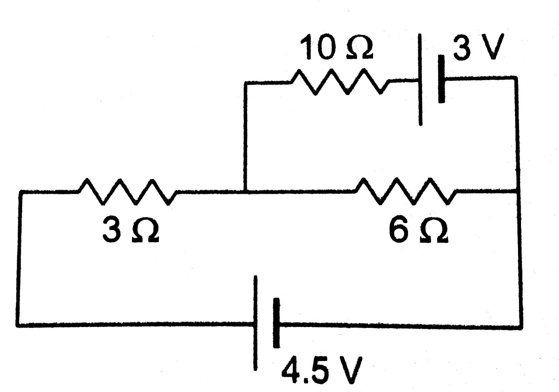
04:21View SolutionFind the current through the `10(Omega)`resistor shown in figure.
 02:38View Solution
Each resistance shown in the network is in ohm. Current through the resistor `3 Omega` is 0.25 A. The input voltage 'V' is equal to
 03:29View Solution
The forward biased conection is :
 01:24View Solution
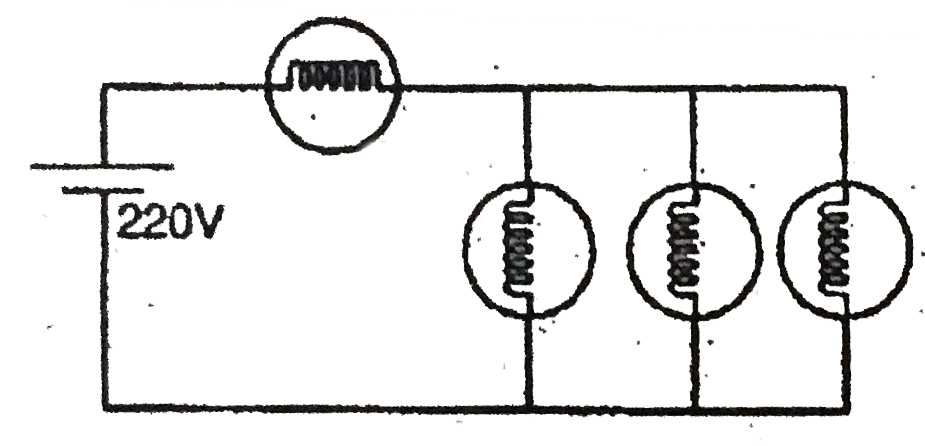
Four identical bulbs each rated 100 watt, 220 volts are connected across a battery as shown. The total electric power consumed by the bulbs is:
 05:29View Solution
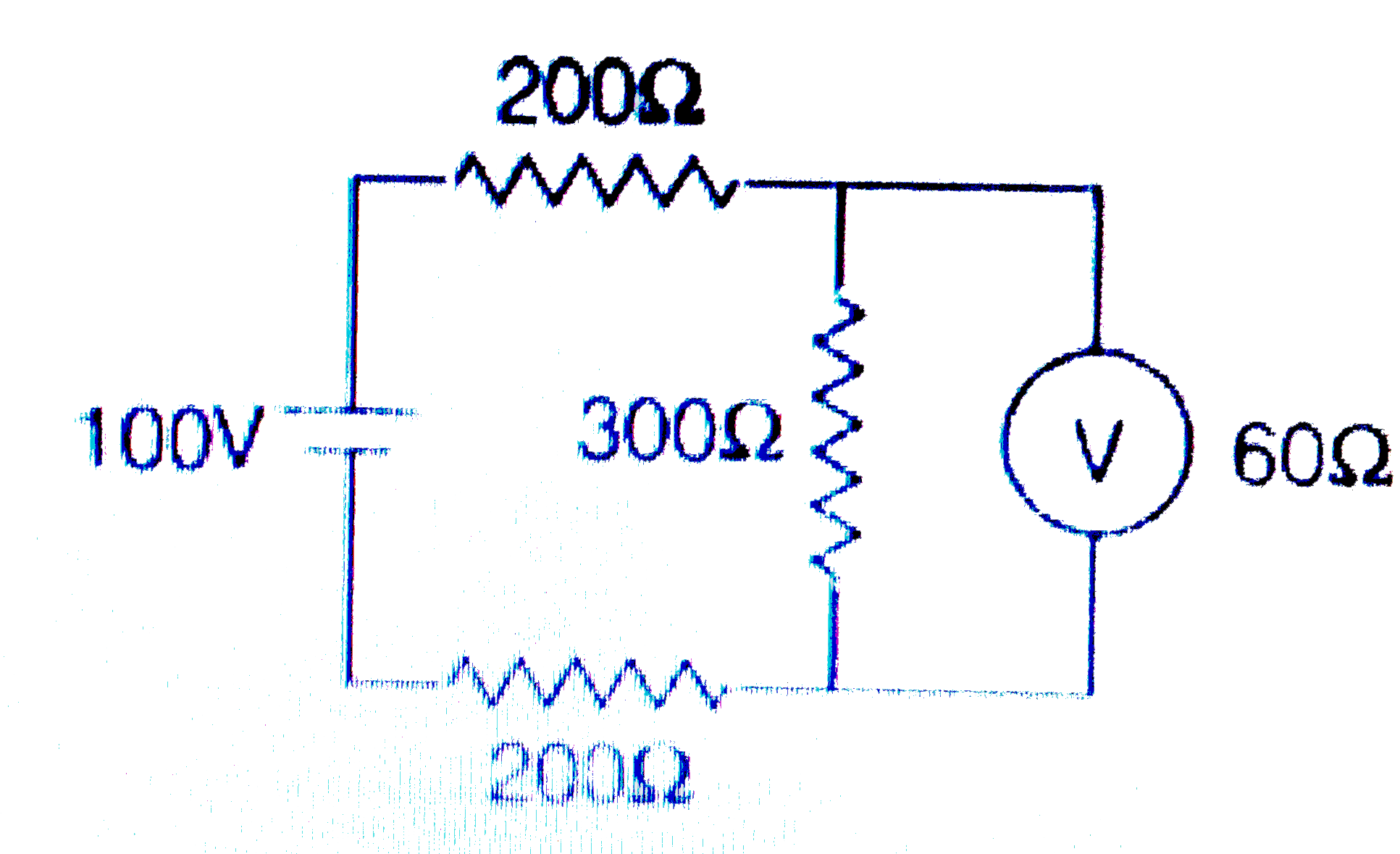
The reading of voltmeter is
 02:16View Solution
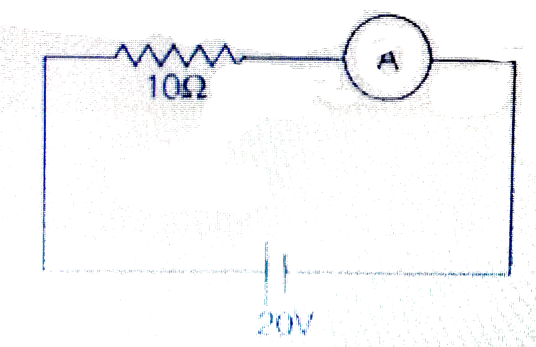
The ammeter shown in figure consists of a `480 Omega` coil connected in parallel to `20 Omega` shunt. Find the reading of the ammeter
 03:54View Solution
When a galvanometer is shunted with a `4 Omega` resistance, the deflection is reduced to one-fifth. If the galvanometer is further shunted with a `2 Omega` wire, determine current in galvanometer now if initially current in galvanometer is `I_(0)` (given main current remains same).
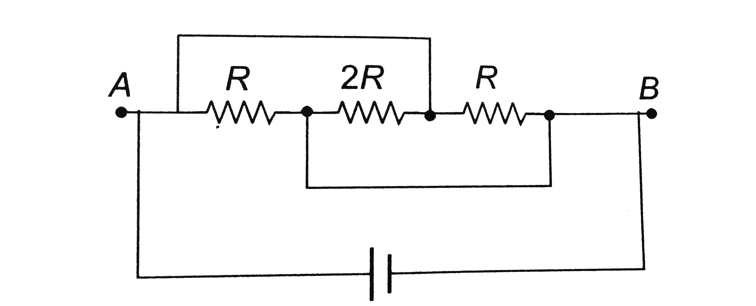
04:20View SolutionIn the figure shown the current flowing `2 R` is:
 03:10View Solution
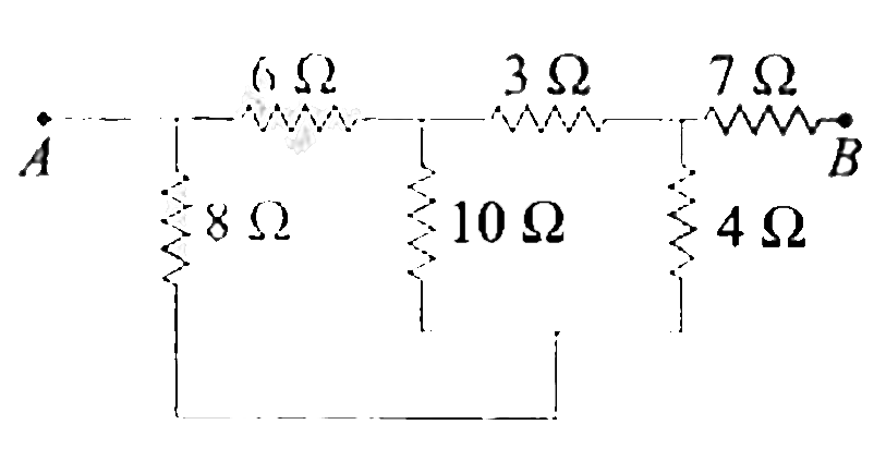
The equivalent resistance between the points A and B is:
 05:34View Solution
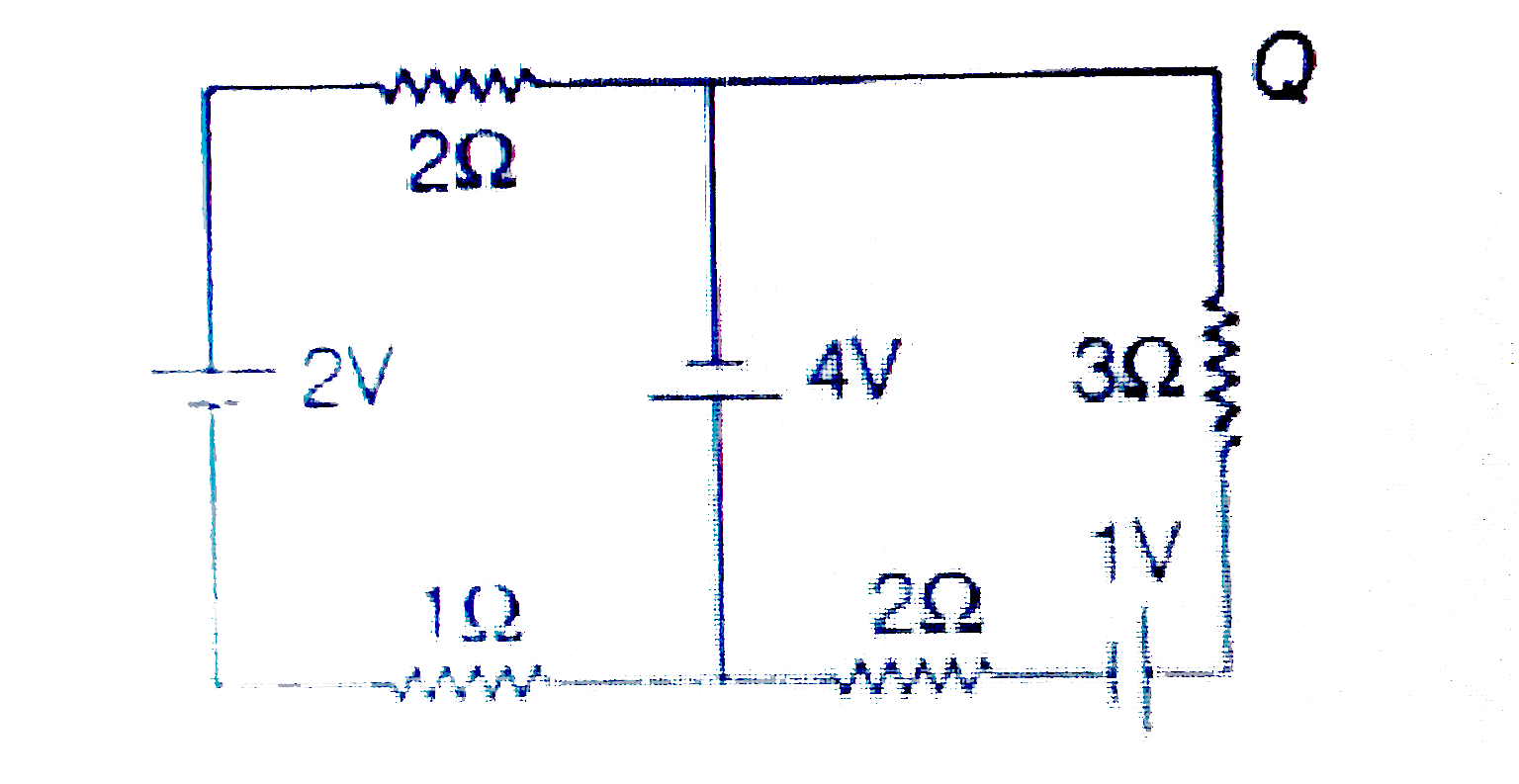
In the circuit shown, what is the potential different `V_(PQ)` ?
 04:49View Solution
Which of the following wiring diagrams could be used to experimentally determine `R` using ohm's law? Assume an ideal voltmeter and an ideal ammeter.
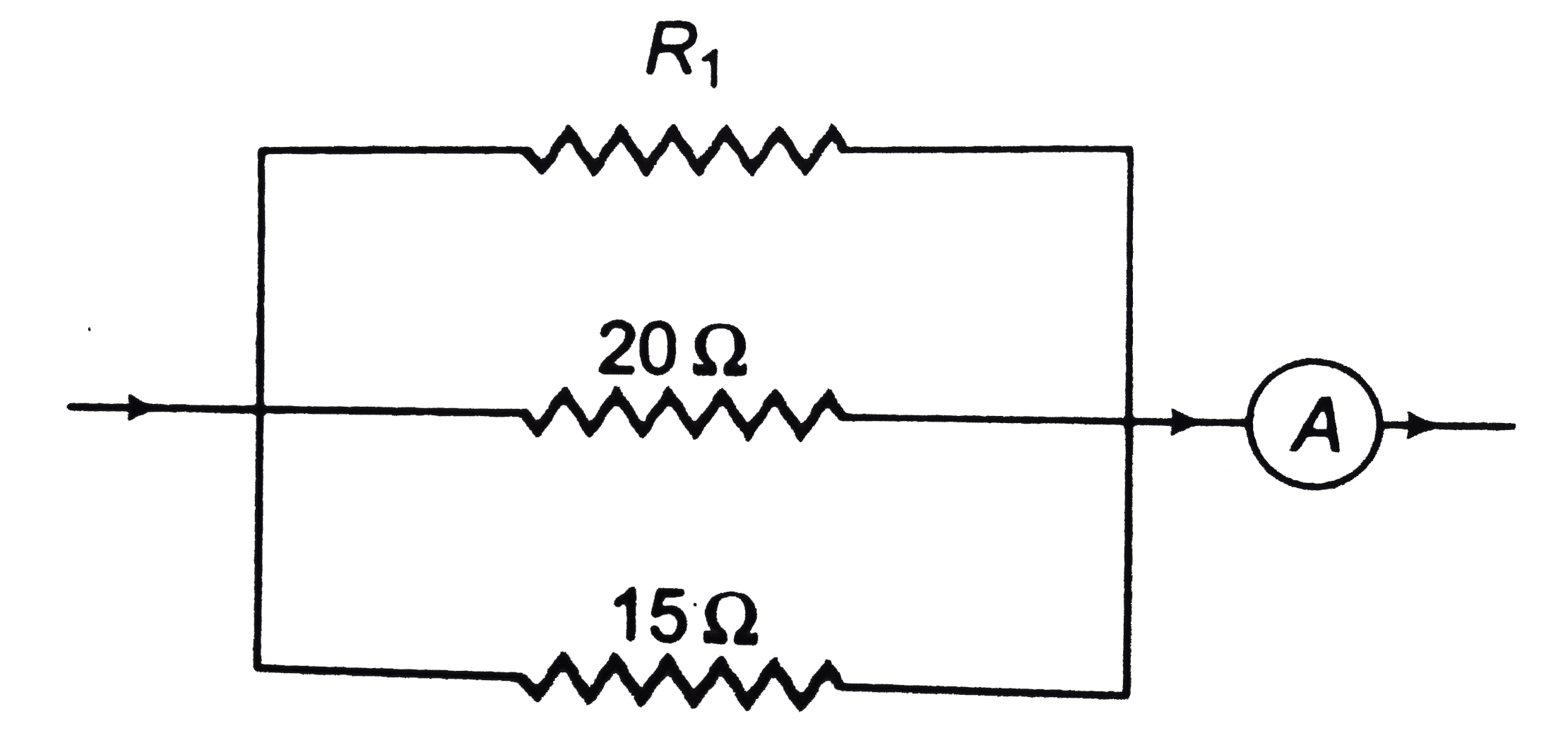
02:24View SolutionIn the given circuit current flowing through the resistance `20Omega` is `0.3A,` while the ammeter reads 0.8 A. What is the value of `R_1`
 03:24View Solution
Power generated across a uniform wire connected across a supply is `H`. If the wire is cut into `n` equal parts and all the parts are connected in parallel across the same supply, the total power generated in the wire is
01:42View SolutionRate of dissipation of Joule's heat in resistance per unit volume is (symbols have usual meaning)
01:33View SolutionThe variation of current `(I)` and voltage `(V)` is as shown in figure `A`. The variation of power `P` with current `I` is best shown by which of the following graph
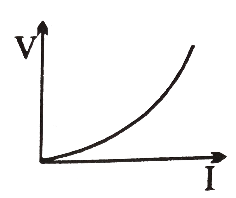 01:14View Solution
Six resistors each of 10 ohm are connected shown. The equivalent resistance between points X and Y is
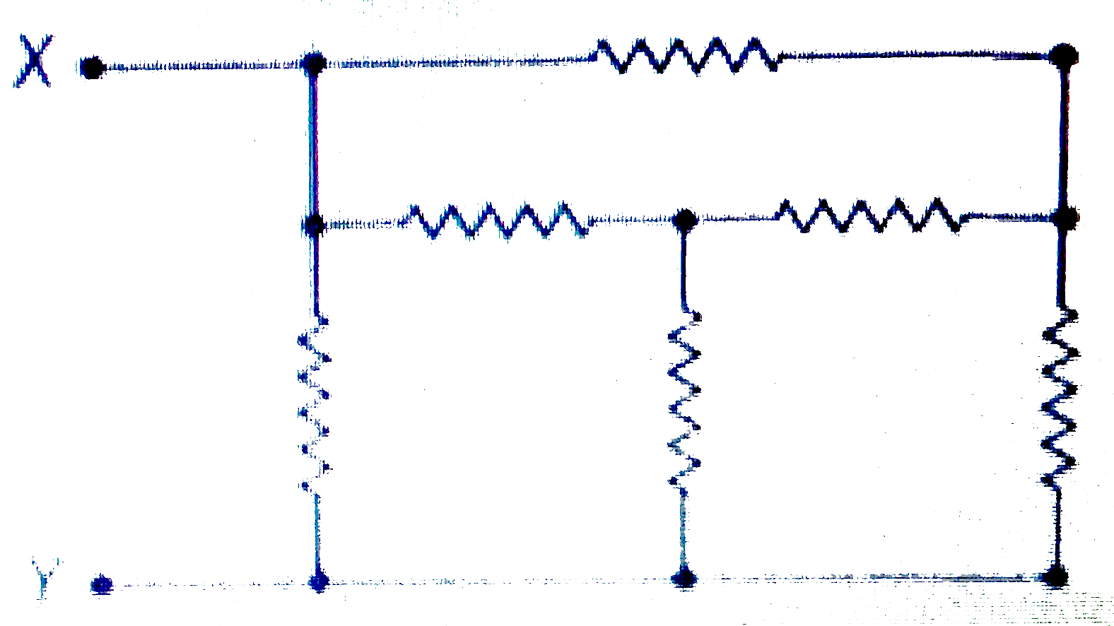 03:42View Solution
Thirteen resistances each of resistance `R` ohm are connected in the circuit as shown in the figure below. The effective resistance between `A` and `B` is
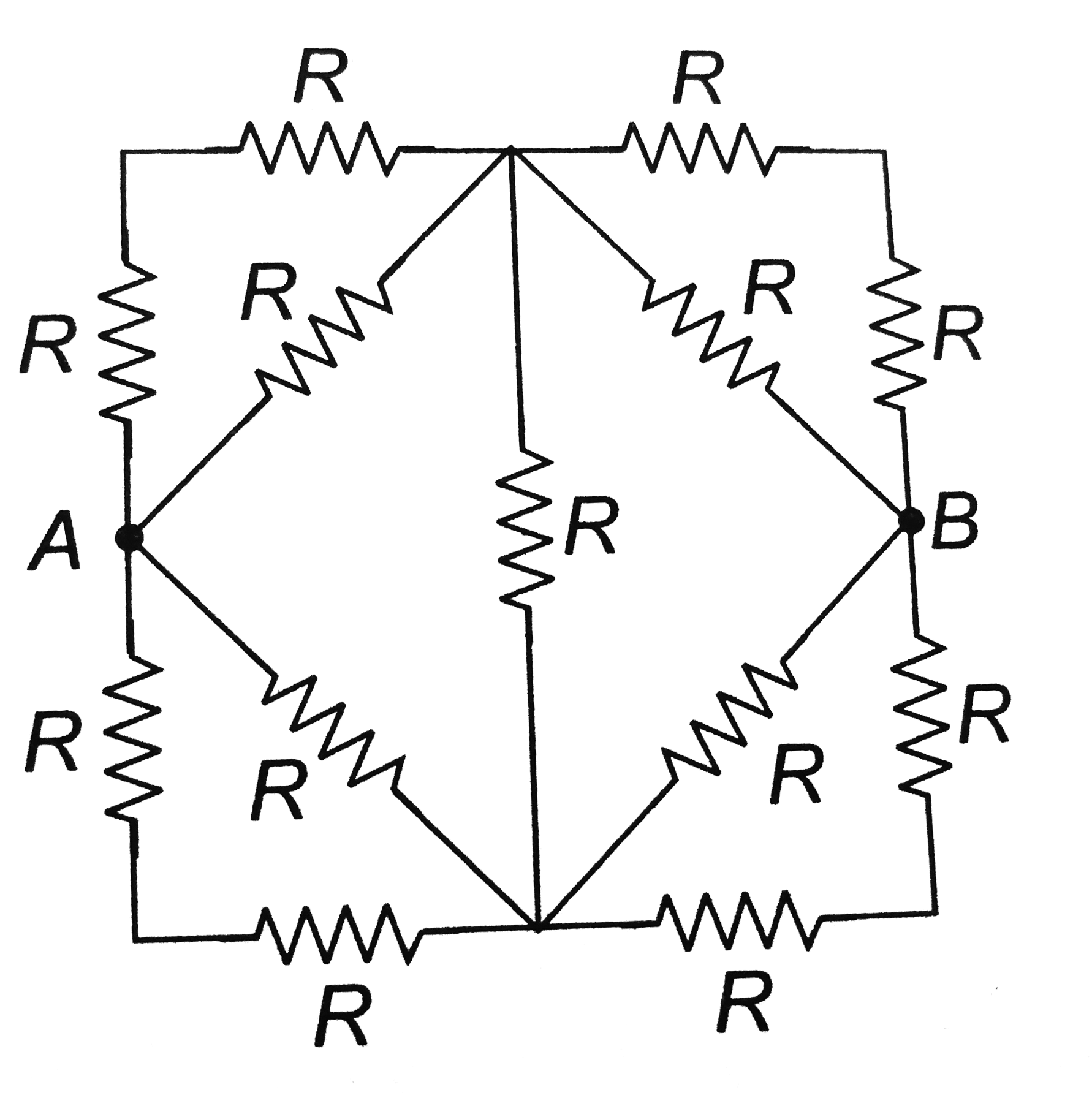 03:14View Solution
In the given network, the euqivalent resistance between A and B is
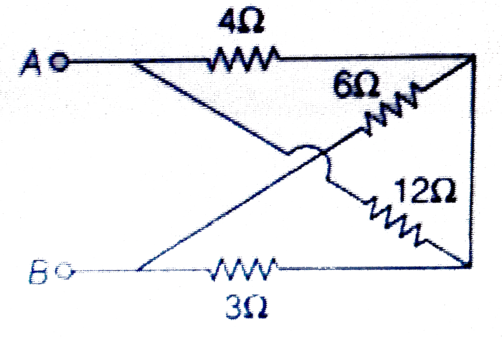 02:44View Solution
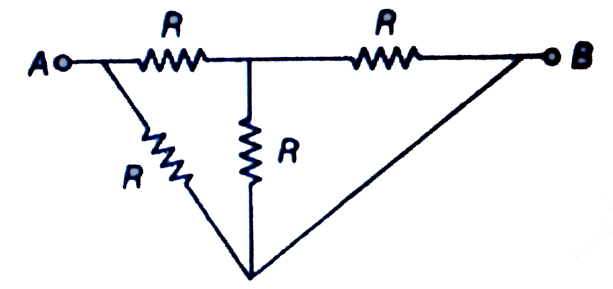
The equivalent resistance between points A and B
 03:18View Solution
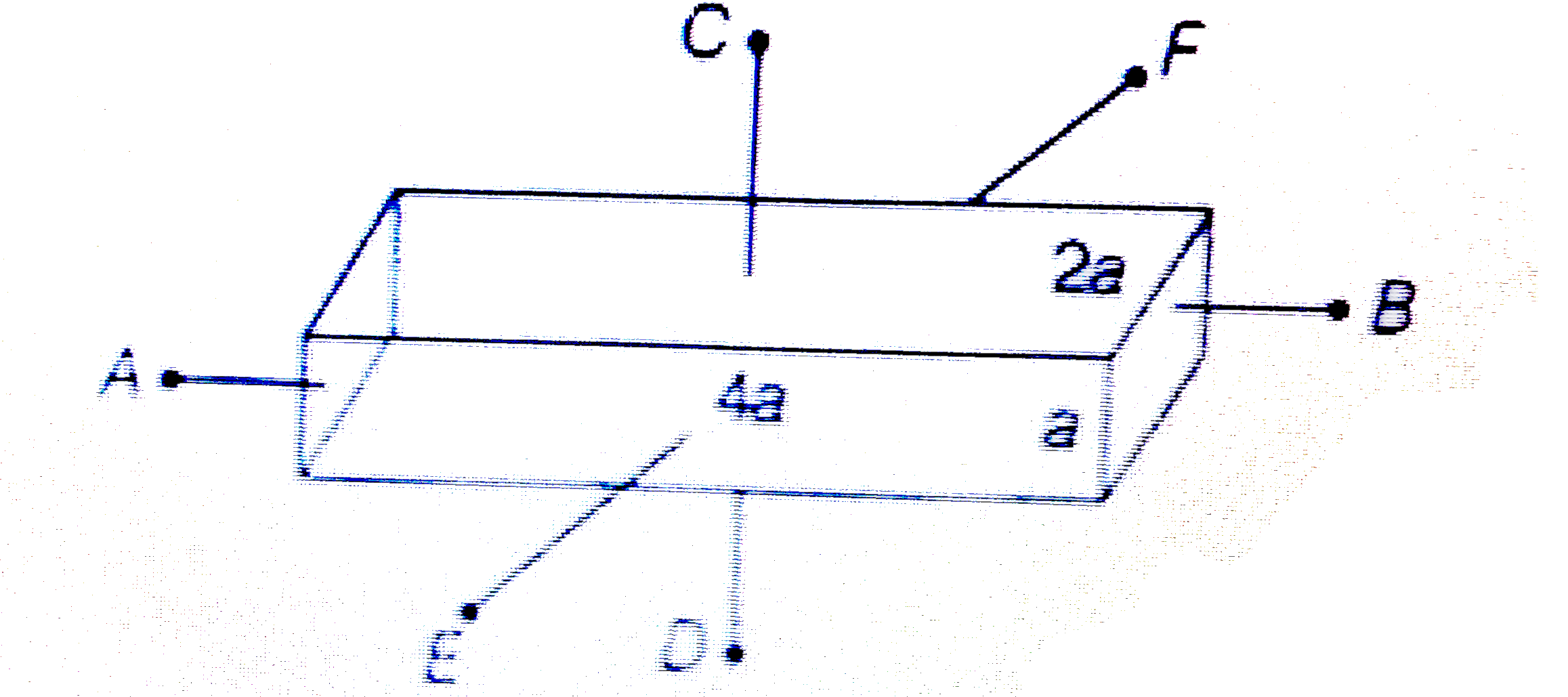
A conductor with rectangular cross section has dimensions `(axx2axx4a)` as shown in figure. Resistance across AB is x, across CD is y and across EF is z. Then
 05:32View Solution
The length of a potentiometer wire is `l`. A cell of emf `E` is balanced at a length l/3 from the positive end of the wire. If the length of the wire is increased by l/2. At what distance will the same cell give a balance point.
02:33View SolutionA cell develops the same power across two resistances `R_(1)` and `R_(2)` separately. The internal resistance of the cell is
04:50View SolutionTwo wires of same dimension but resistivity `p_(1)` and `p_(2)` are connected in series. The equivalent resistivity of the combination is
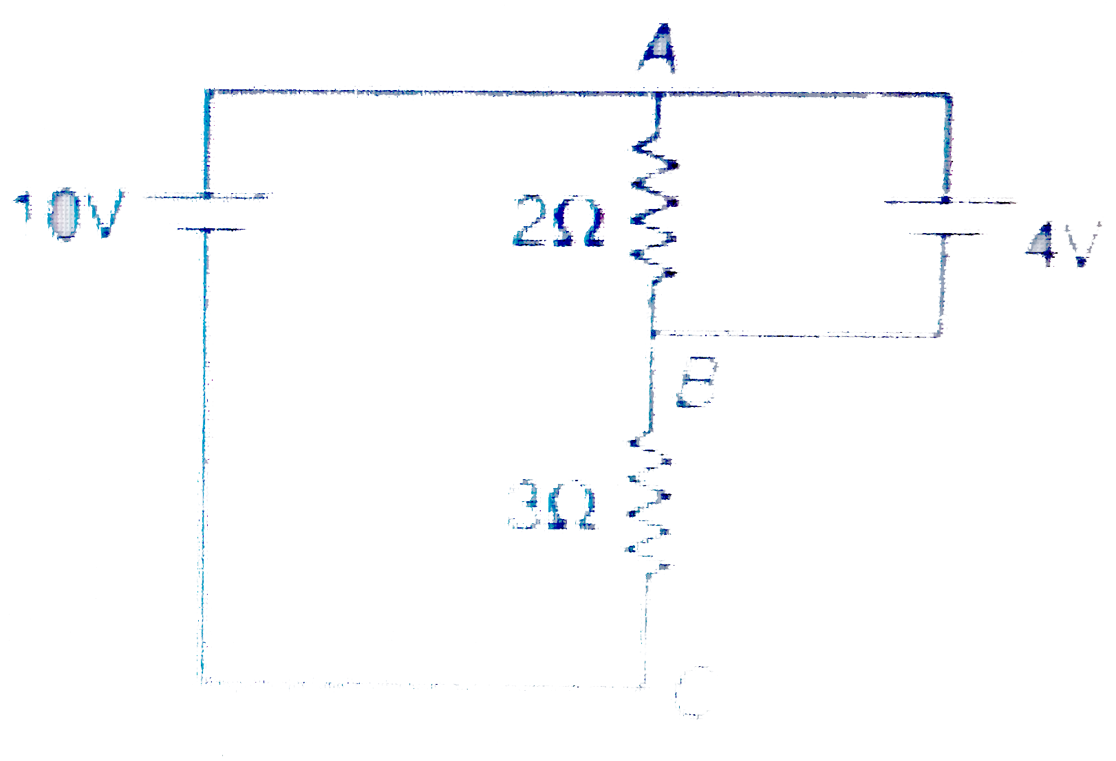
02:14View SolutionCurrent passing through `3 Omega` resistance is
 02:18View Solution
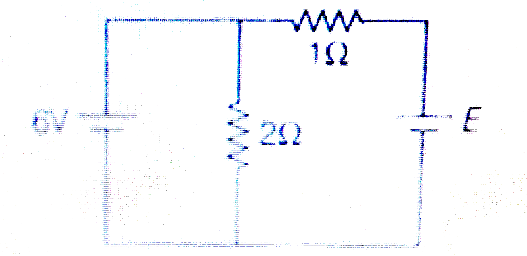
Current passing through `1 Omega` resistance is zero. Then the emf E is
 01:15View Solution
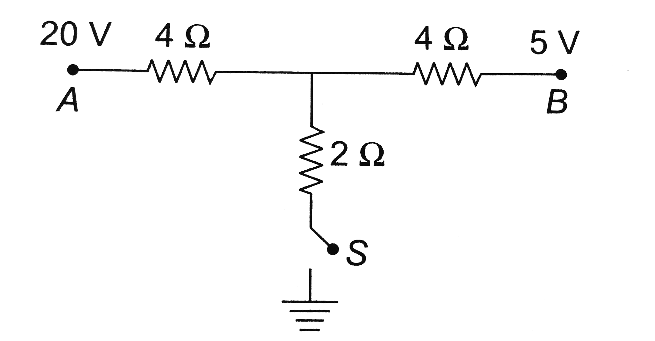
As the switch `S` is closed in the circuit shown in figure, current passed through it is.
 03:02View Solution
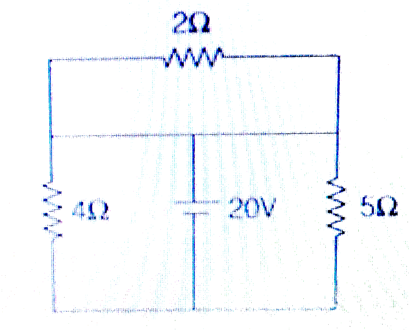
In the circuit shown in figure
 01:54View Solution
Find equivalent resistance between A and B
 01:39View Solution
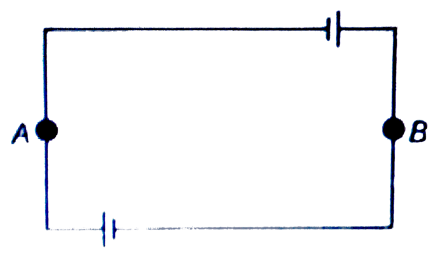
Two identical batteries, each having emf of 1.8 V and of equal internal resistances are connected as shown in the figure. Potential difference between A and B will be equal to (Ignore the resistance of lead wires)
 03:13View Solution
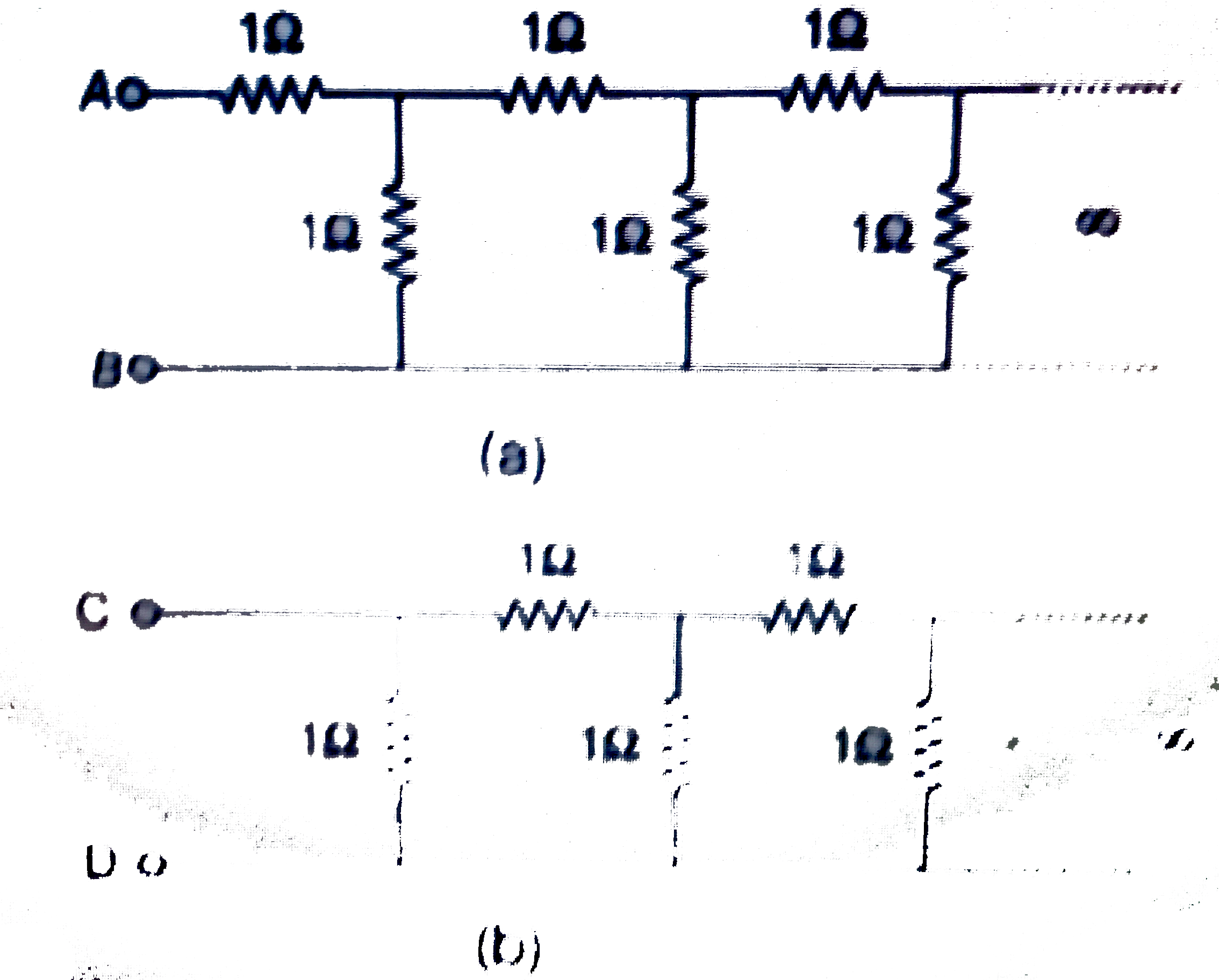
In the two circuits shown in figure
 03:15View Solution
The net resistance between points P and Q in the circuit shown in figure is
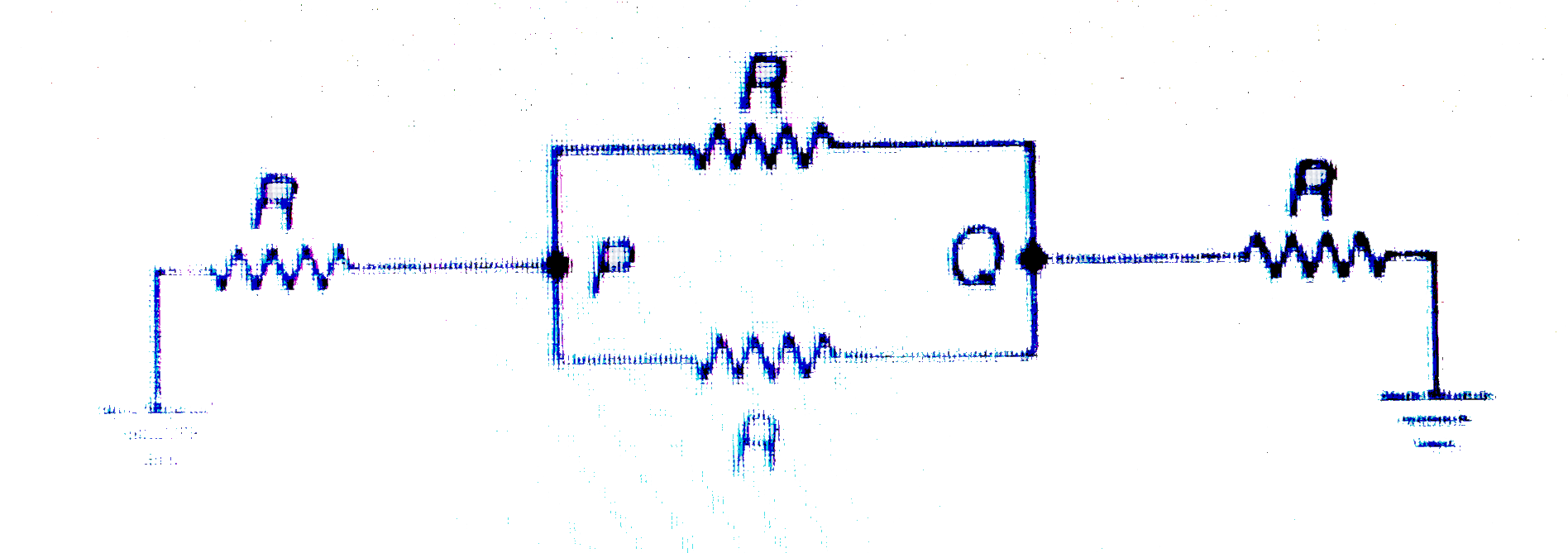 03:37View Solution
Current in `3 Omega` resistance is
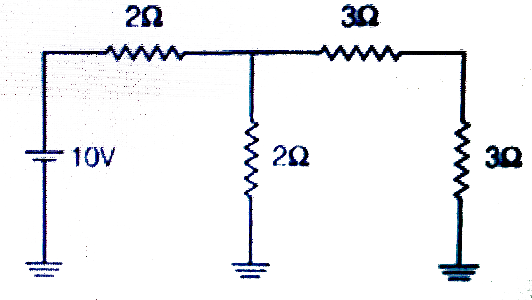 05:28View Solution
A galvanometer of resistance `R_(G)` is to be converted into an ammeter, with the help of a shunt of resistance R. If the ratio of the heat dissipated through galvanometer and shunt is 3:4, then
01:46View SolutionThe equivalent resistance between points A and B
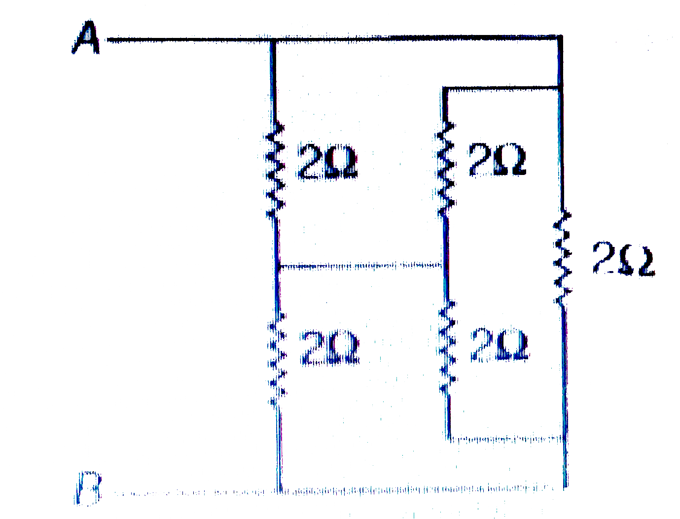 03:20View Solution
In the circuit shown in figure, each resistance is Net resistance between points A and B is
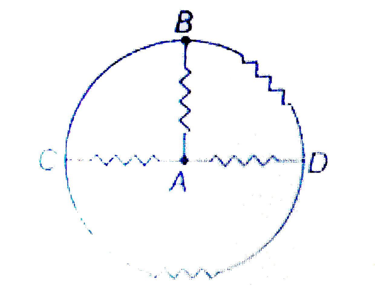 03:05View Solution
In the same figure, equivalent resistance between points A and D is
02:29View SolutionEach resistance of the circuit shown in figure is r. The equivalent resistance between A and B is
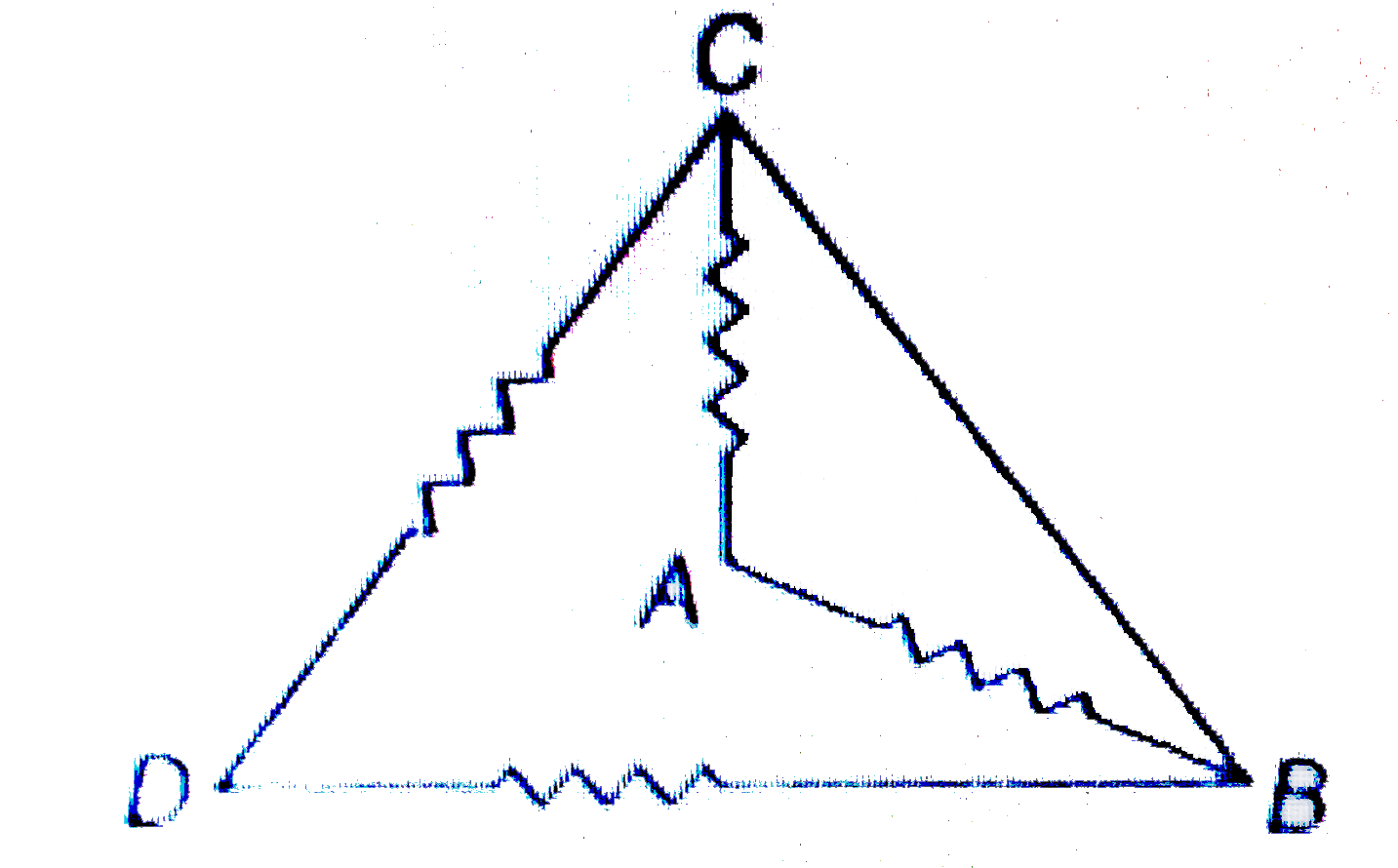 02:42View Solution
As shown, the circuit is made of 8 different resistance. It is found that when `R_(1) = 4 Omega`, the resistance between A and B is `2 Omega`. Now replace `R_(1)` by a `6 Omega` resistor, what is the resistance between A and B ?
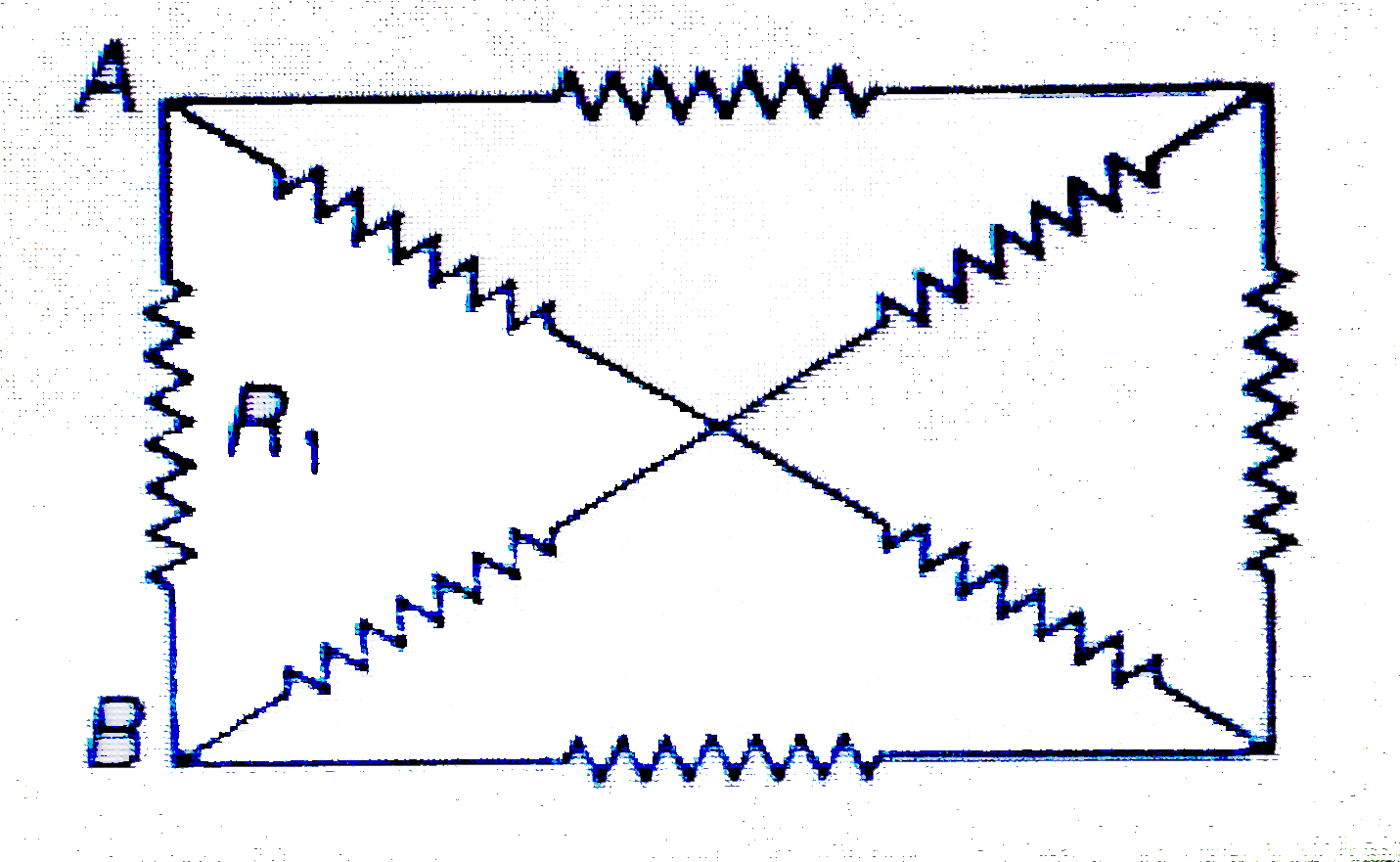 01:20View Solution
Resistance of each resistor is R. Then the equivalent resistance across A and B is
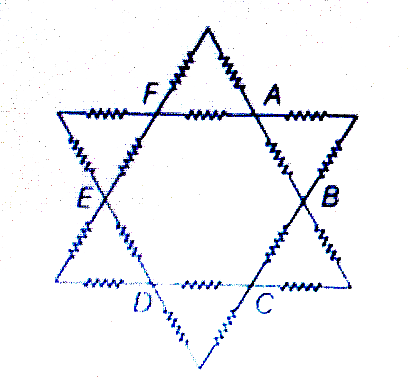 02:31View Solution
In the given circuit the power dissipated through resistance `R_(1) = 9 Omega` is `P_(1)`, when switch `S_(1)` is closed and `S_(2)` is opened and the power dissipated through resistance `R_(2) = 4 Omega` is `P_(2)`, when switch `S_(2)` is closed and `S_(1)` is opened. If `P_(1) = P_(2)`, then r is equl to :
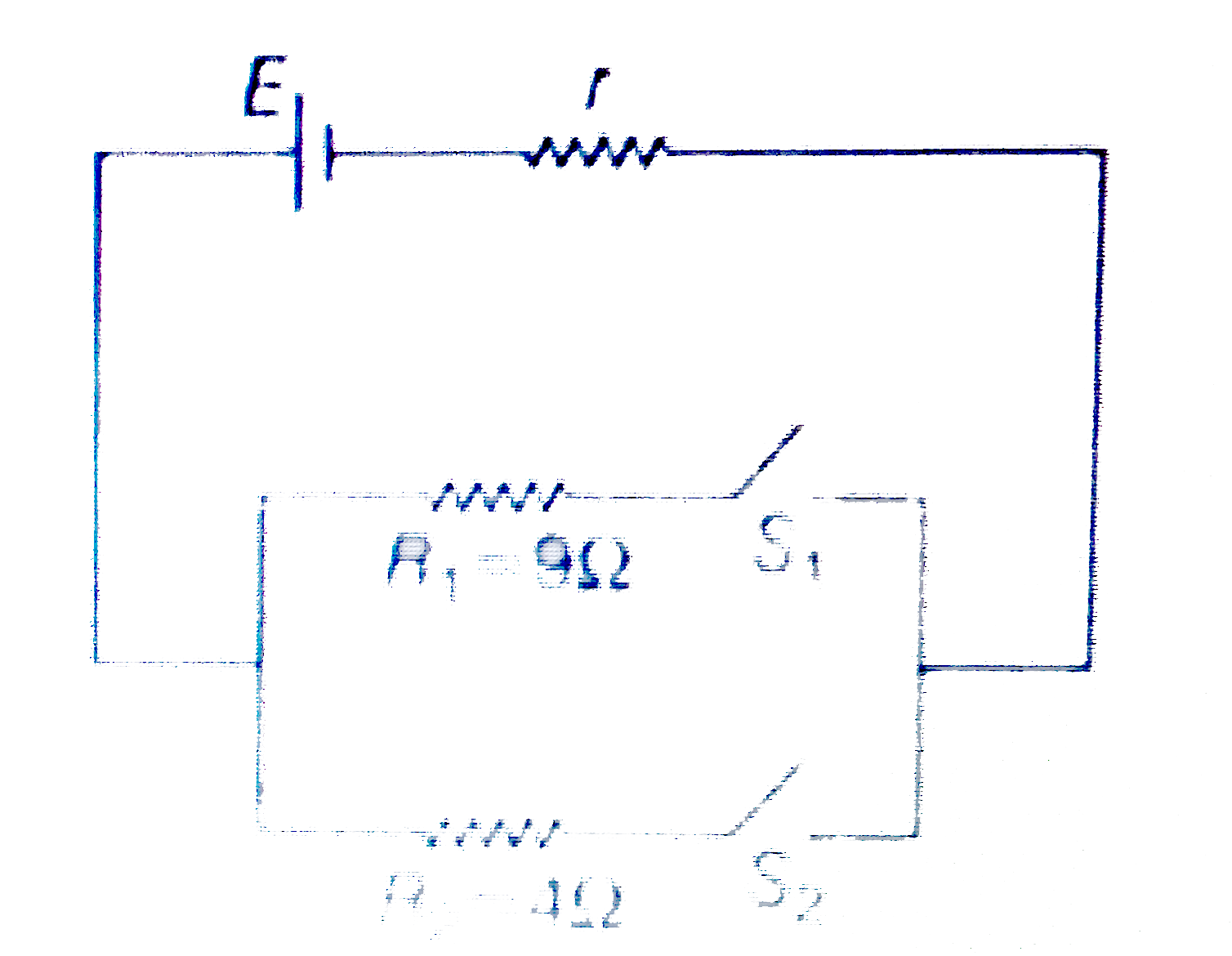 02:24View Solution
A copper disc and a carbon disc of same radius are assembled alternately and co-axially to make a cylindrical conductor whose temperature coefficient conductor whose temperature coefficient of resistance is almost equal to zero. Ratio of thickness of the copper and the carbon disc is (neglect change in length. `alpha_(CU)` and `-alpha_(C)` represent the temperature coefficients of resistivities and `p_(cu)` carbon at room temperature respectively)
03:06View SolutionFind equivalent resistance between A and B
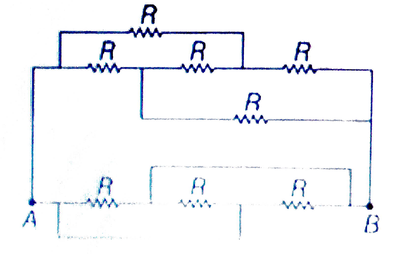 04:33View Solution
Find equivalent resistance between A and D
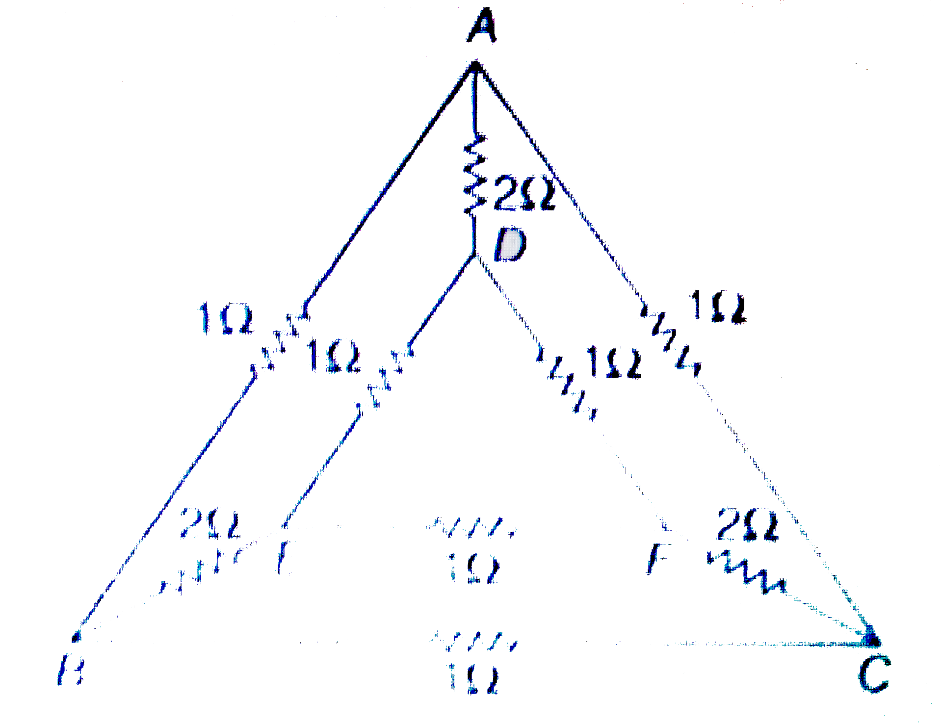 01:48View Solution
Calculate equivalent resistance between A and C
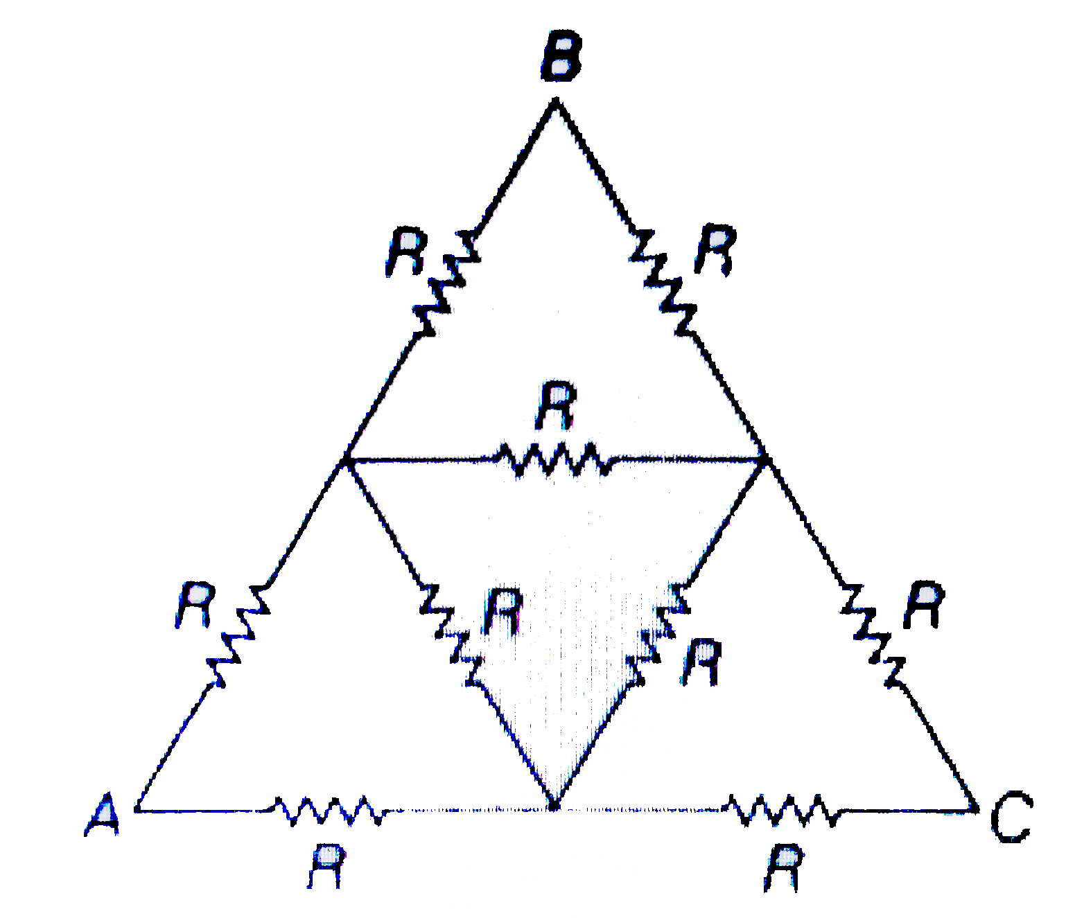 02:52View Solution
In the circuit shown below, V should be:
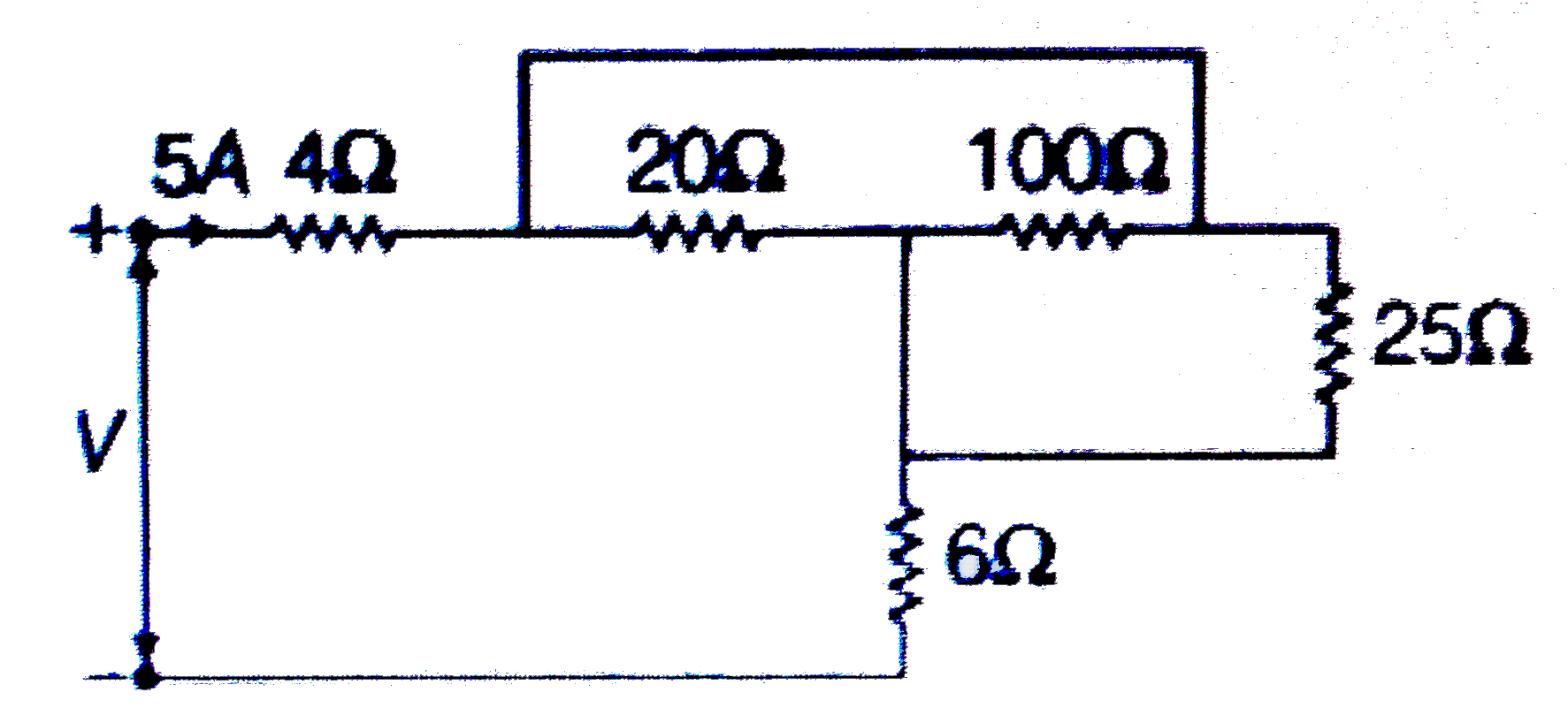 03:58View Solution
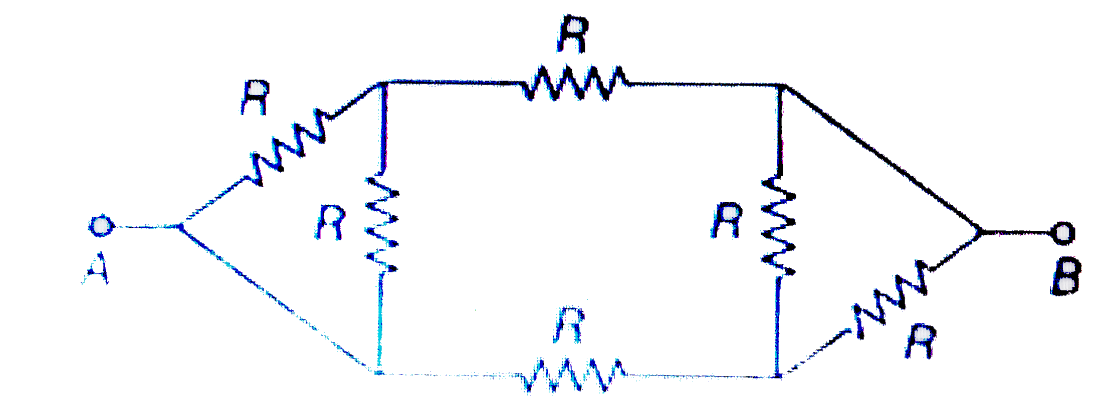
Equivalent resistance between A and B is
 02:58View Solution
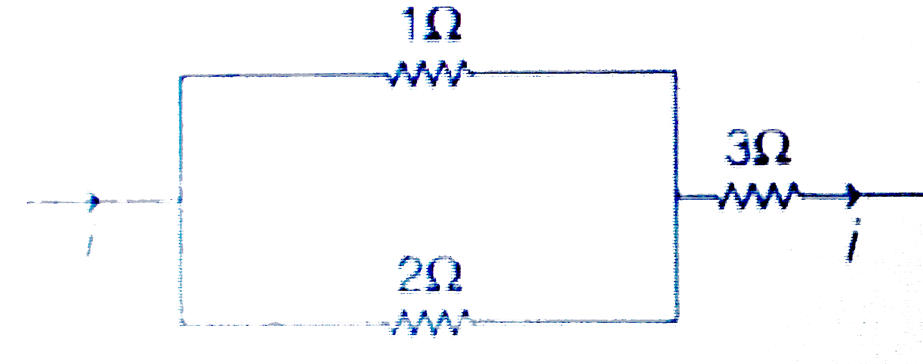
In the circuit shown in figure, power developed across `1 Omega, 2 Omega` and `3 Omega` resistance are in the ratio of
 02:18View Solution
A moving coil galvanometer of resistance `20 Omega` gives a full scale deflection when a current of `1mA` is passed through it. It is to be converted into an ammeter reading `20 A` on full scale. But the shunt of `0.005 Omega` only is available. What resistance should be connected in series with the galvanometer coil?
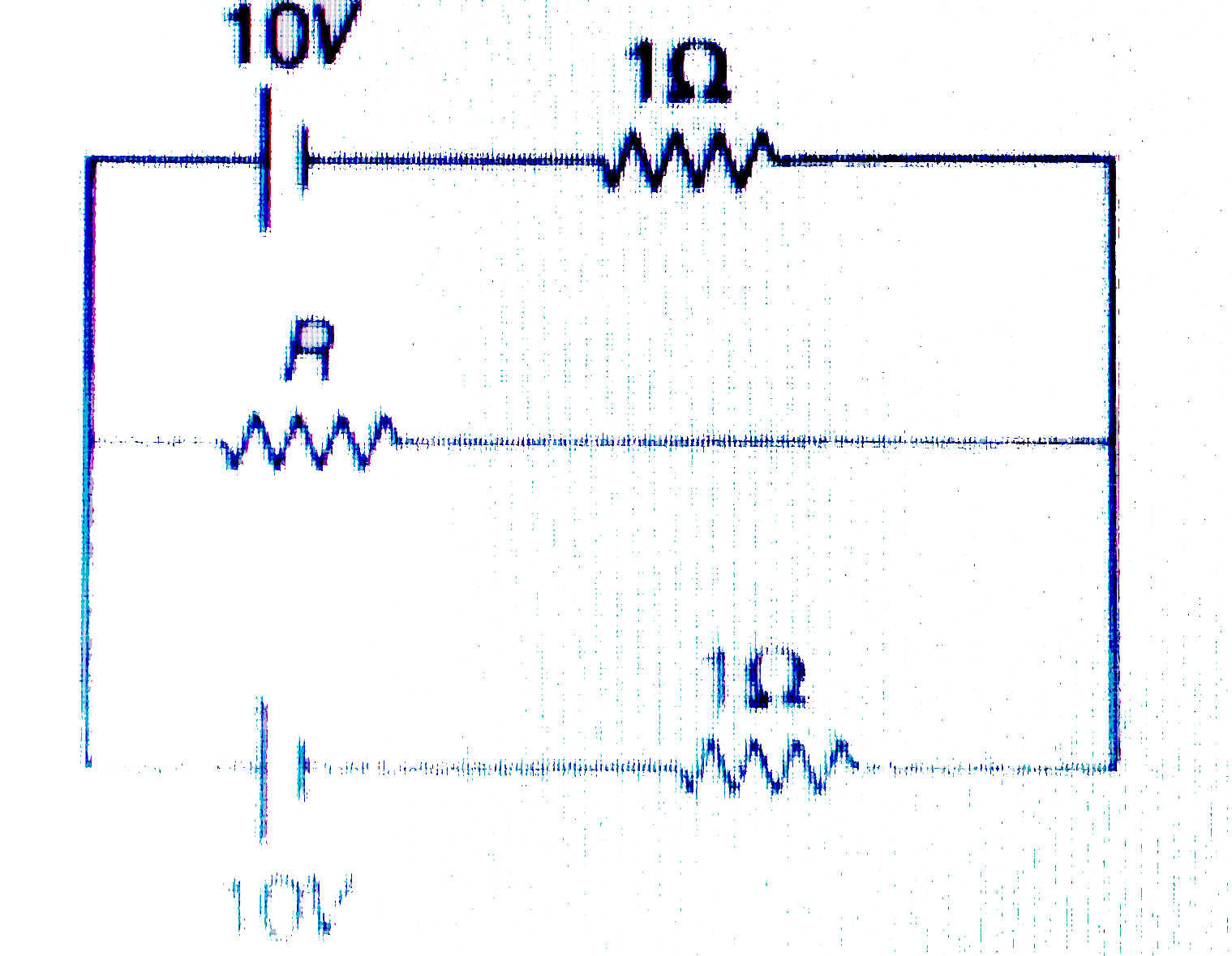
03:06View SolutionMaximum power developed across variable resistance R in the circuit shown in figure is
 07:38View Solution
Resistance of a resistor at temperature `t^@C` is `R_t =R_0 (1+alphat + betat^2)`, where `R_0` is the resistance at `0^@C`. The temperature coefficient of resistance at temperature `t^@C` is
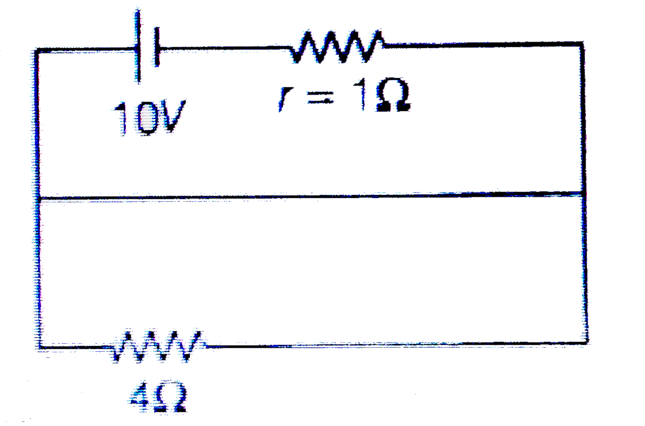
03:23View SolutionPotential different across the terminals of the battery shown in figure is
 01:12View Solution
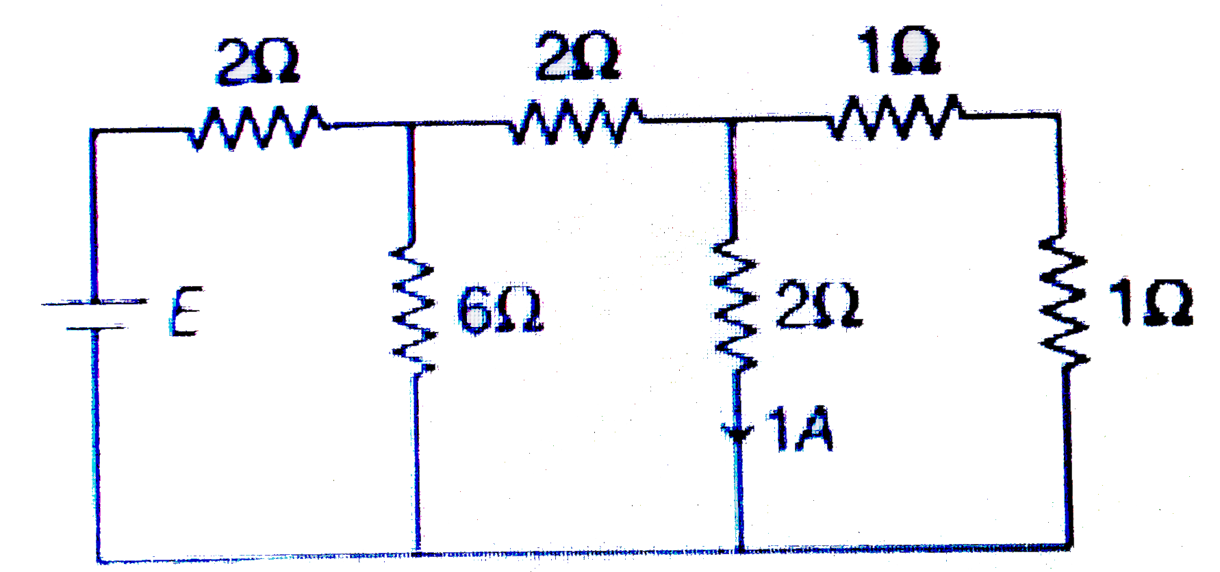
The emf of the battery shown in figure is
 05:37View Solution
A voltmeter with resistance `500 Omega` is used to measure the emf of a cell of internal resistance `4 Omega`. The percentage error in the reading of the voltmeter will be
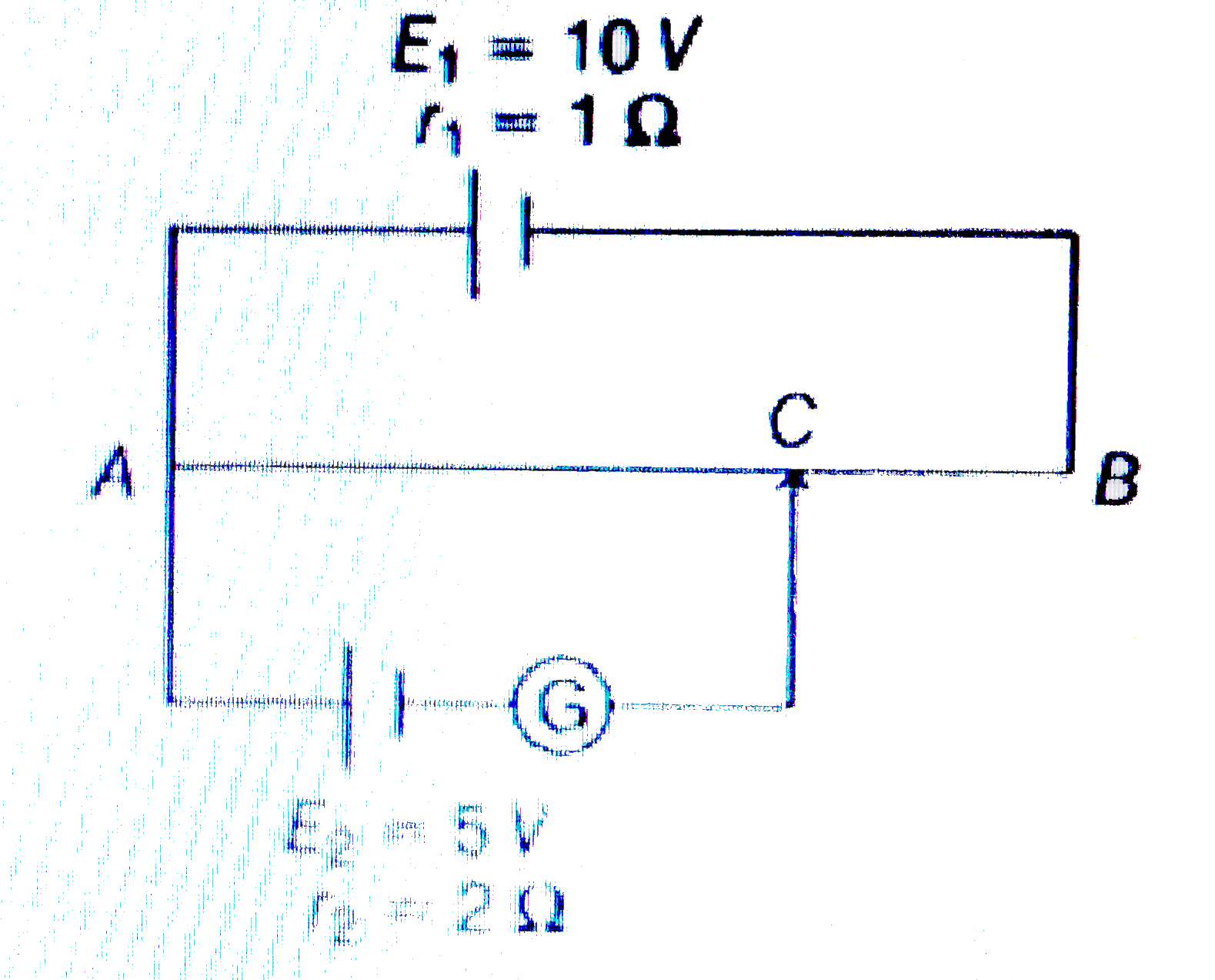
04:26View SolutionIn the figure, the potentiometer wire of length `l = 100 cm` and resistance `9 Omega` is joined to a cell of emf cell of emf `E_(2) = 5 V` and internal resistance `r_(2) = 2 V` is connected as shown. The galvanometer is show no deflection when the length AC is
 01:50View Solution
The potential difference across the terminals of a battery is 10 V when there is a current of 3 A in the battery from the negative to the positive terminal. When the current is 2A in the reverse direction, the potential difference becomes 15 V. The internal resistance of the battery is
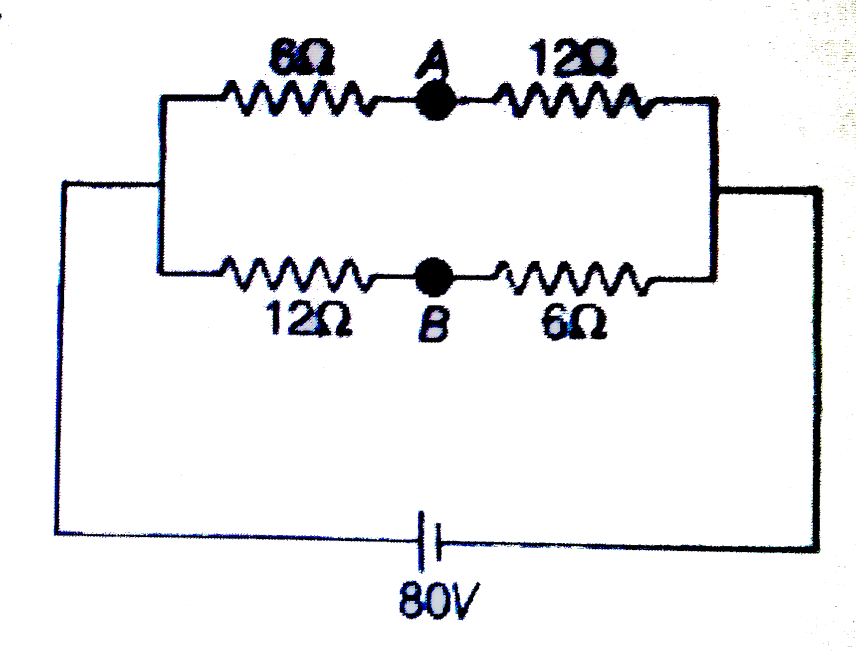
02:23View SolutionIn the circuit shown, if a wire is connected between points A and B. How much current will flow through that wire?
 03:46View Solution
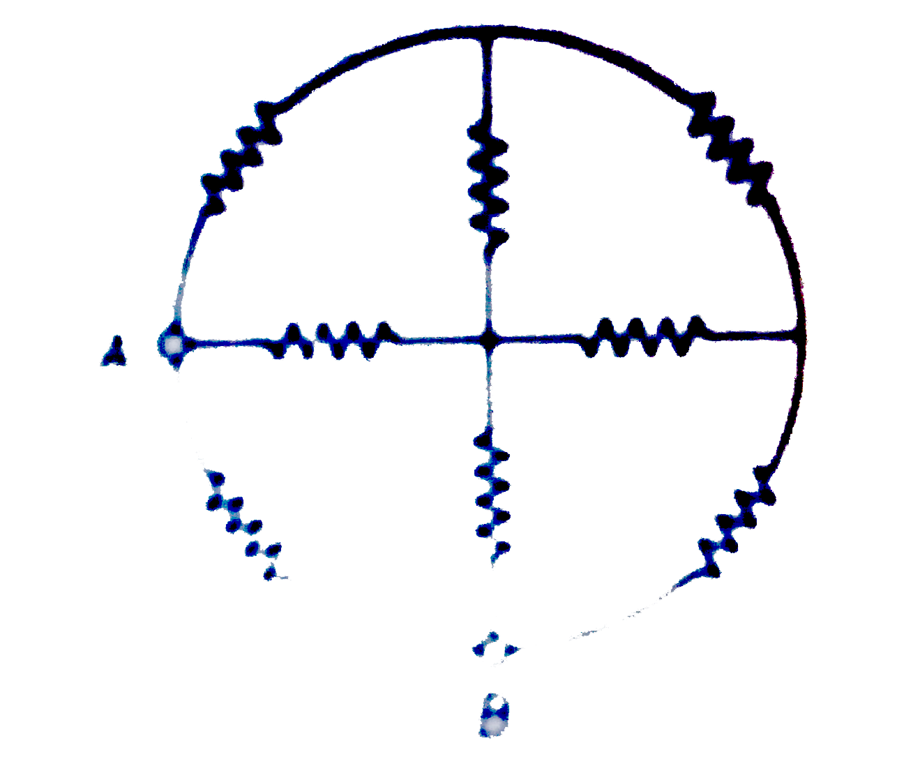
Eight resistances each of resistance `5 Omega` are connected in the circuit as shown in figure. The equivalent resistance between A and B is
 02:49View Solution
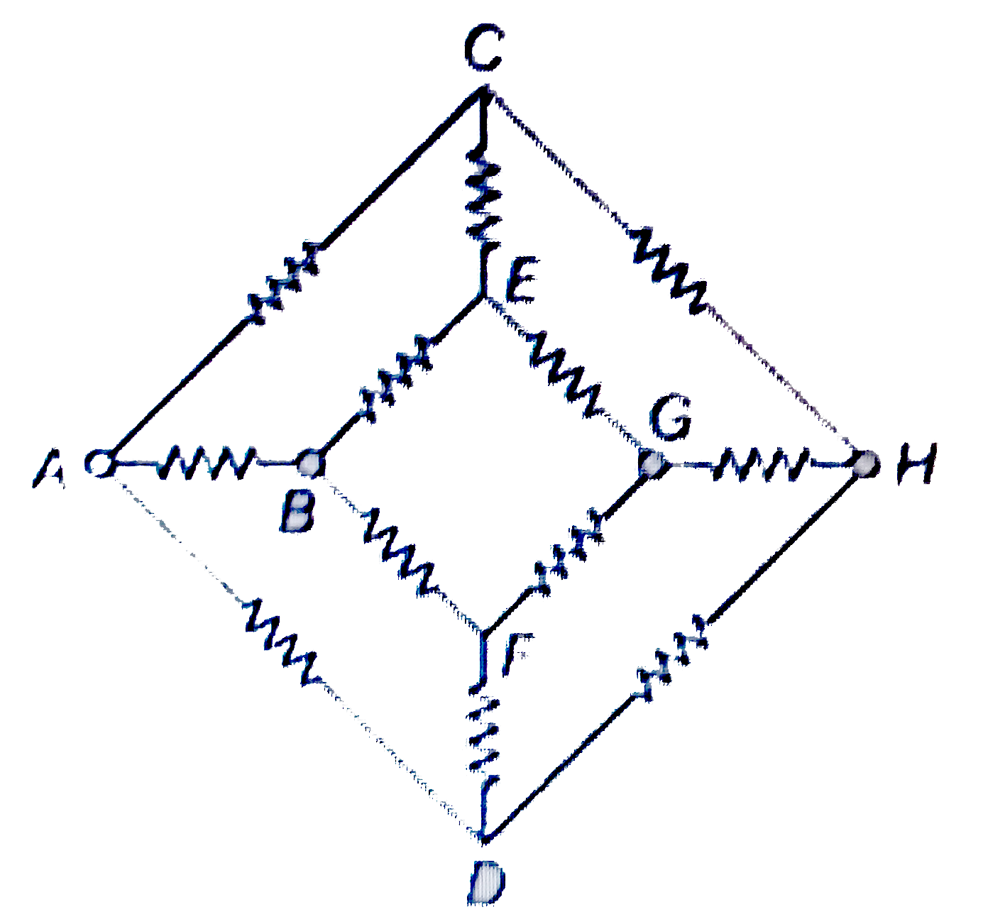
Twelve resistors each of resistance `1 Omega` are connected in the circuit shown in figure. Net resistance between point A and H would be
 03:49View Solution
`n` identical cells are joined in series with two cells A and B with reversed polarities. EMF of each cell is E and internal resistance is r. Potential difference across cell A or B is (n > 4)
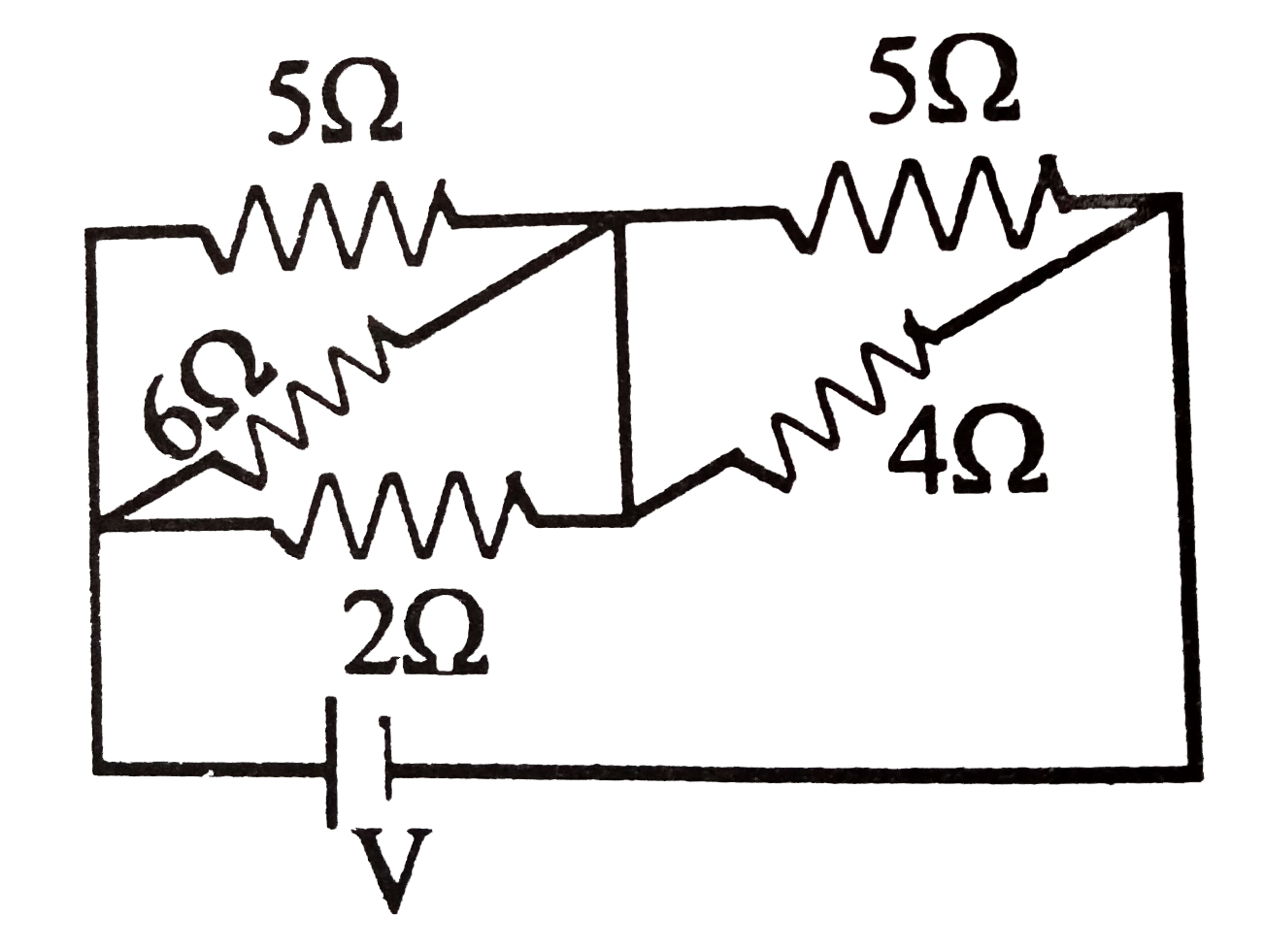
06:25View SolutionFind the resistor in which maximum heat will be produced.
 04:19View Solution
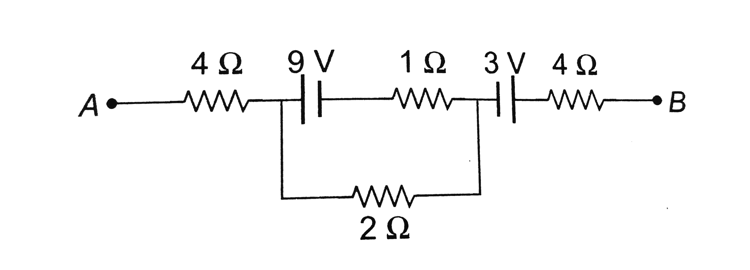
In the circuit shown in figure potential difference between point `A` and `B` is `16 V`. Find the current passing through `2 Omega` resistance.
 04:55View Solution
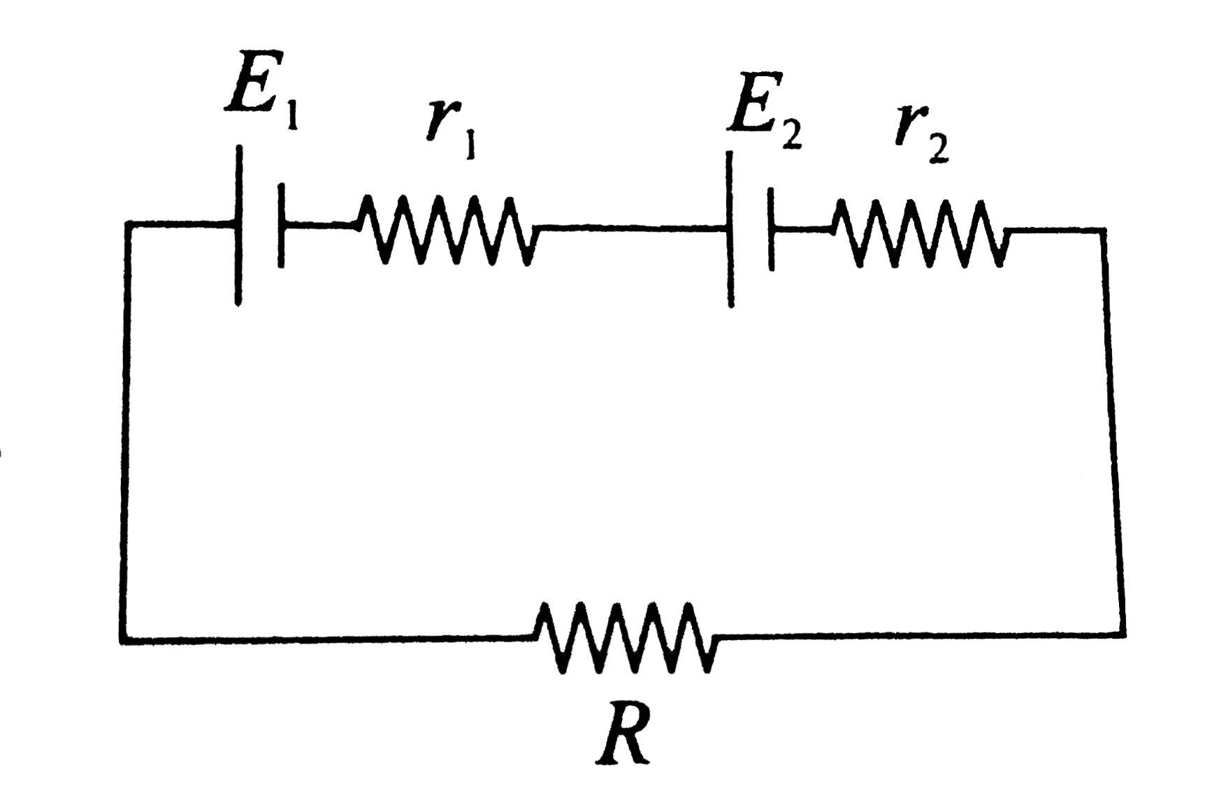
Under what condition, the current passing through the resistance R can be increased by short - circuiting the battery of emf `E_2` The internal resistances of the two batteries are `r_1 and r_2,` respectively.
 04:56View Solution
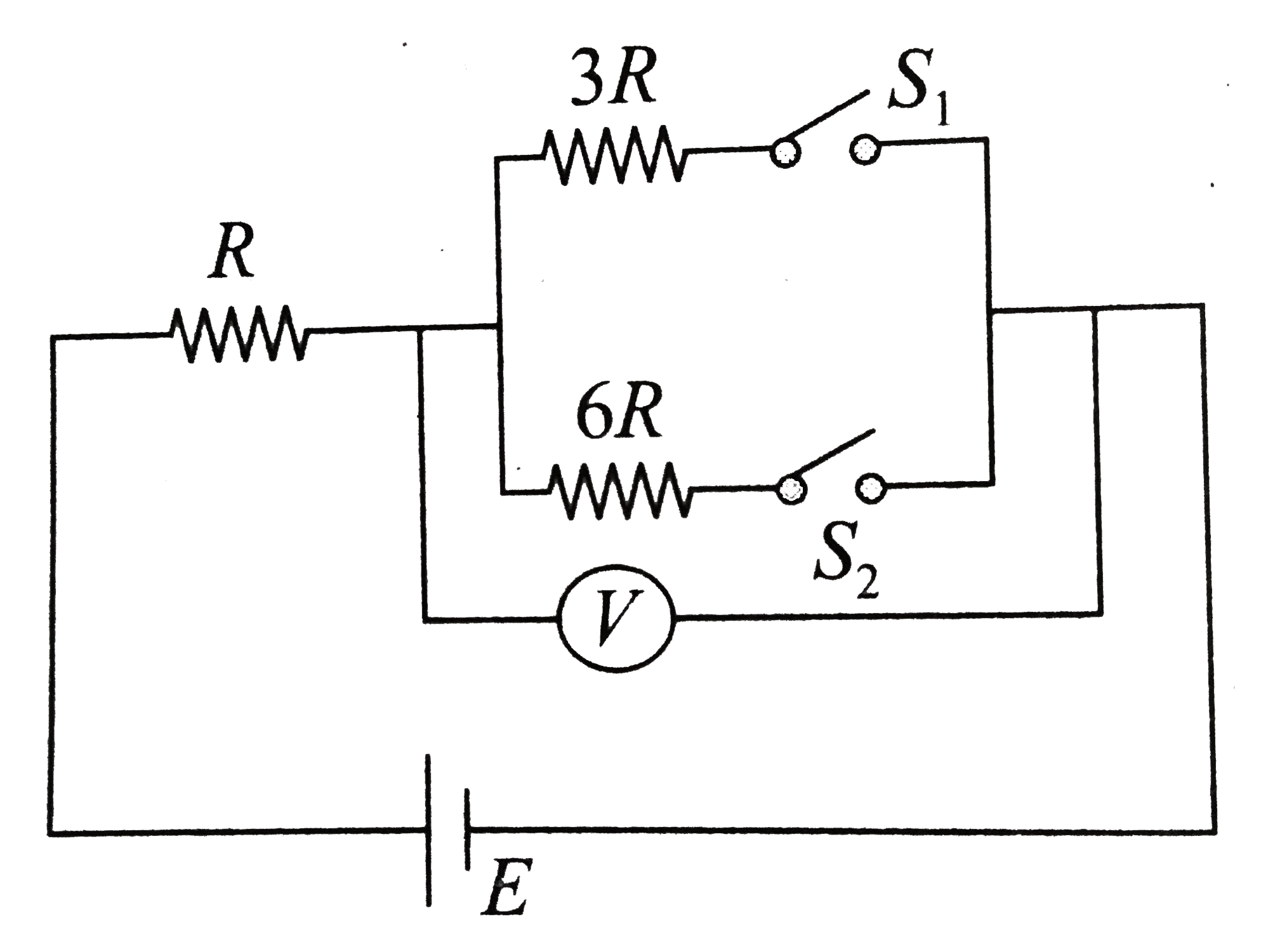
In the circuit shown in figure, reading of voltmeter is `V_1` when only `S_1` is closed, reading of voltmeter is `V_2` when only `S_2` is closed, and reading of voltmeter is `V_3` when both `S_1 and S_2` are closed. Then .
 03:21View Solution
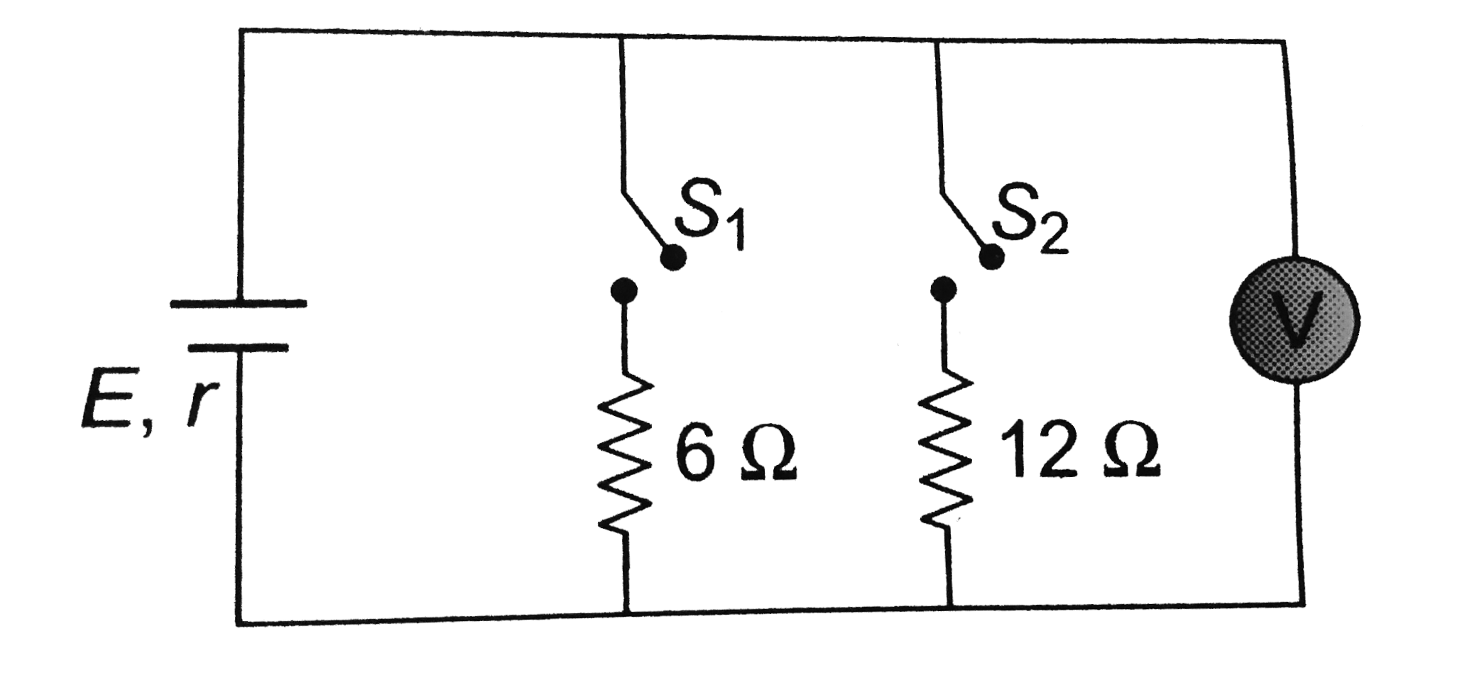
In the circuit shown, when switch `S_(1)` is closed and `S_(2)` is open, the ideal voltmeter shows a reaiding of `18 V`. When switch `S_(2)` is closed and `S_(1)` is open, the reading of voltmeter is `24 V`. When `S_(1)` and `S_(2)` both are closed, the voltmeter reading will be
 04:18View Solution
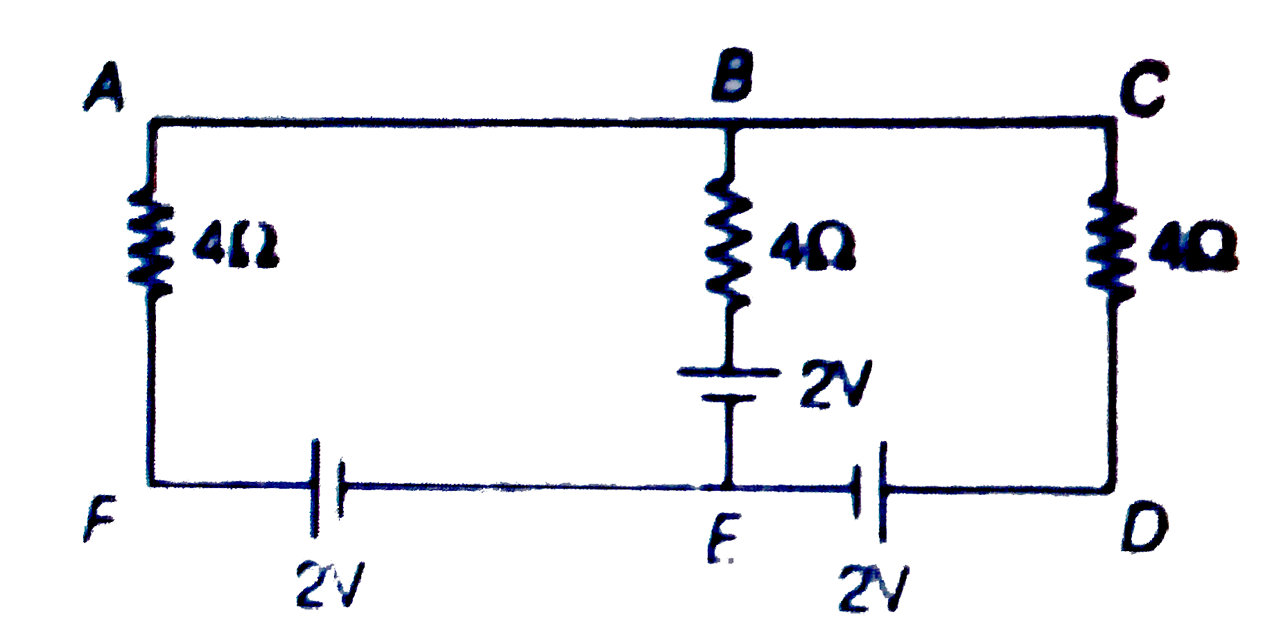
In the circuit shown in figure
 04:57View Solution
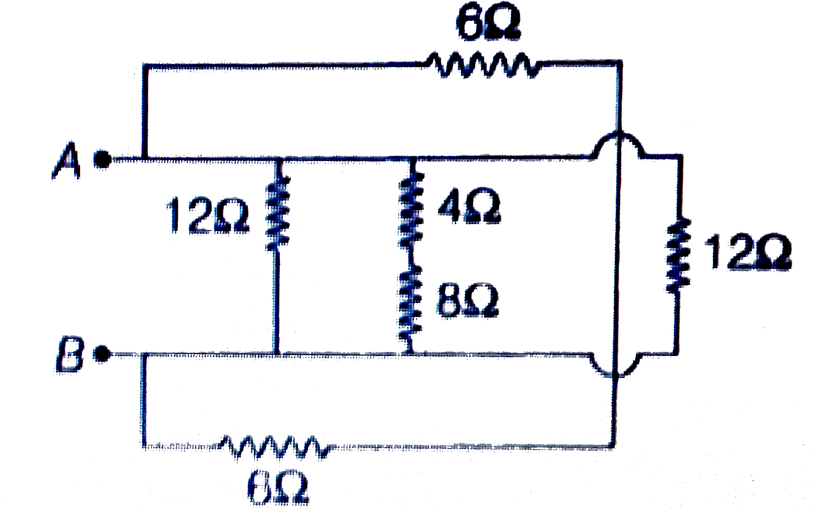
The equivalent resistance across AB in the given network is
 02:55View Solution
The `n` rows each containinig `m` cells in series are joined parallel. Maximum current is taken from this combination across jan external resistance of `3 Omega` resistance. If the total number of cells used are 24 and internal resistance of each cell is `0.5 Omega` then
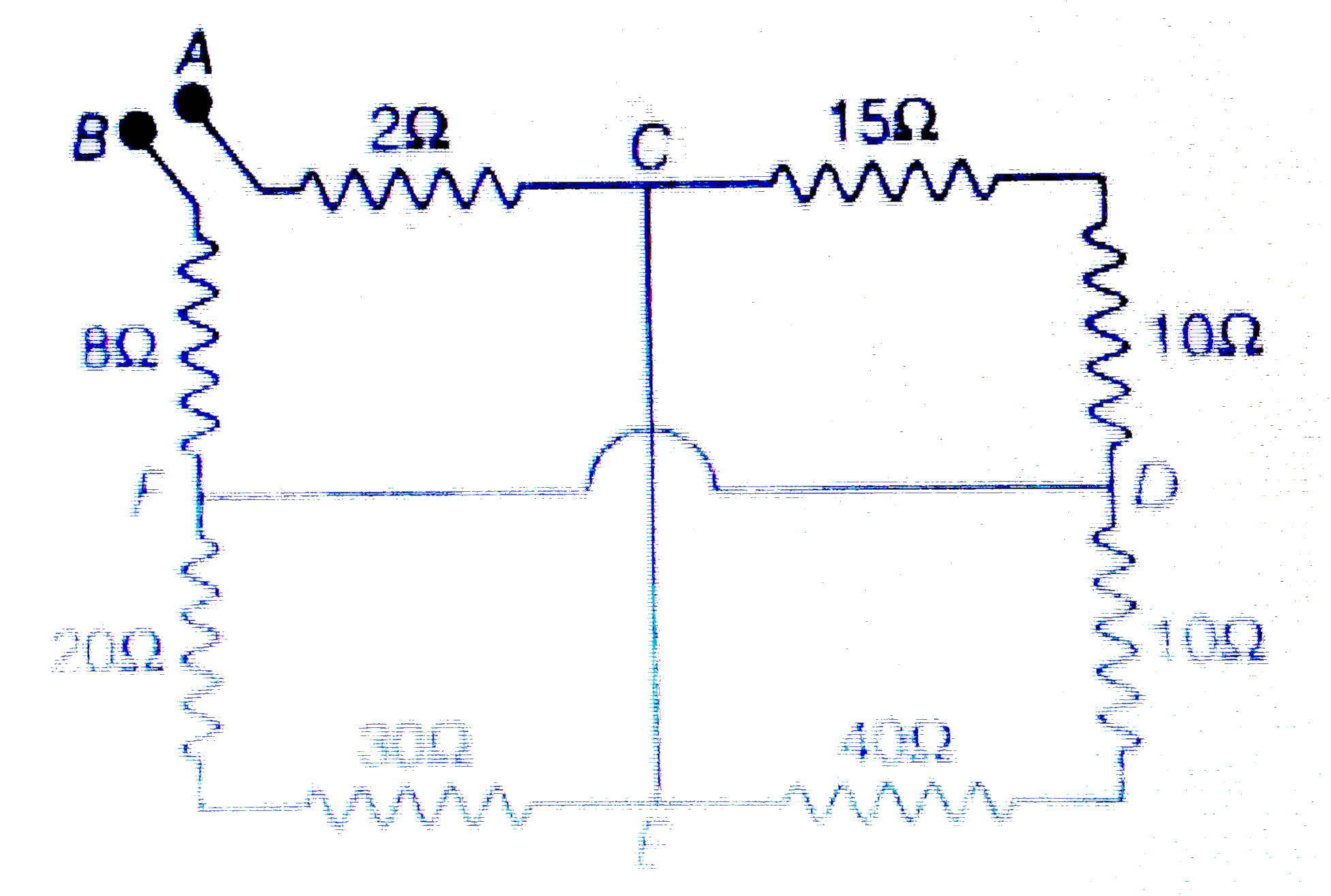
02:17View SolutionThe equivalent resistance between points A and B is
 04:43View Solution
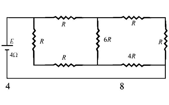
A battery of internal resistance `4Omega` is connected to the network of resistance as shown . In order that the maximum power can be delivered to the network, the value of R in `Omega` should be
 . 08:52View Solution
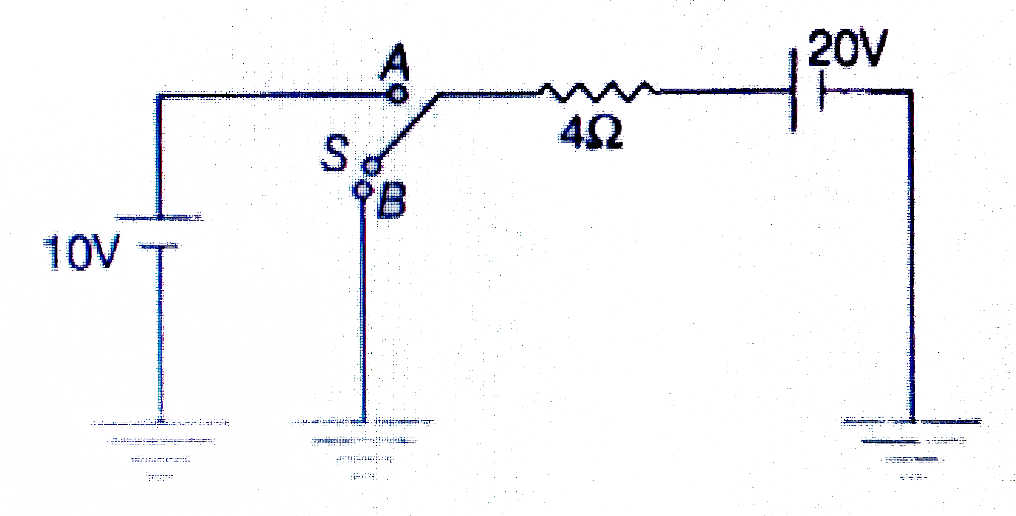
In the circuit shown in figure switch S can be shift to position A or position B. Current though resistance is say `i_(1)` when switch is in position. A and when switch is in position B, then
 03:16View Solution
A galvanometer has resistance G and full scale deflection current i. To convert this galvanometer into an ammeter of range 10 I, a shunt `S = (G)/(9)` is connected in parallel with G. Now we want to measure potential difference with the help of this ammeter. What is the maximum value of potential difference which can be measured with the help of this?
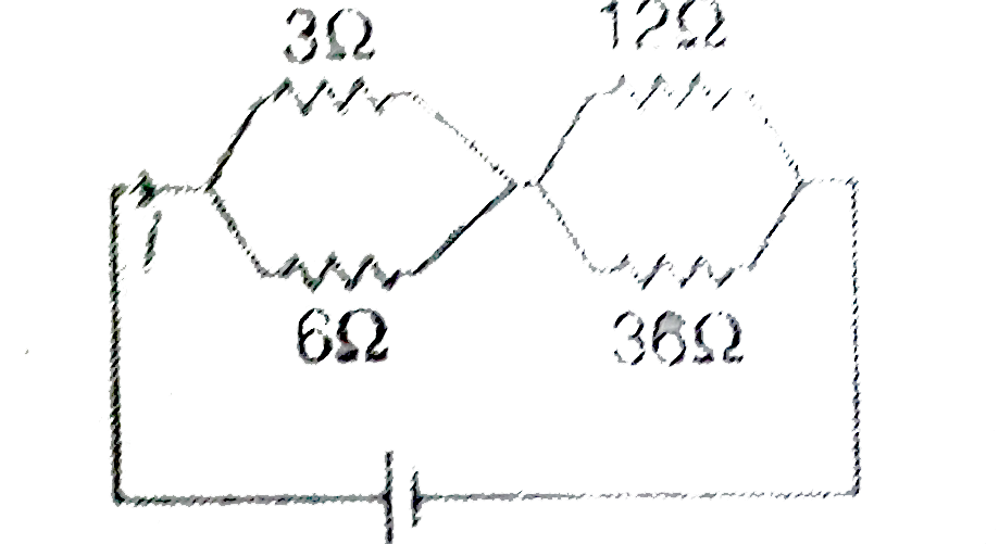
01:56View SolutionFour resistance are connected to a DC battery as shown in figure. Maximum power will be developed across ......... Ohm resistance.
 07:14View Solution
A hollow cylinder of specific resistance `rho`, inner radius `R`, outer radius `2R` and length l is as shown in figure. What is the net resistance between the inner and outer surfaces?
04:42View SolutionA group of identical cells (all in parallel) are connected to an external resistance `R_(1)`. Current through `R_(1)` is `i_(1)`. Another group of identical cells (all in series) are connected to some other resistance `R_(2)`. Current through `R_(2)` is `i_(2)`. Now one cell is removed from both the groups. Then
07:24View SolutionFive identical cells are connected in parallel. Now, polarity of one of the cells is reversed. Percentage change in equivalent emf will be
04:10View SolutionIn the circuir shown in figure, current is zero through
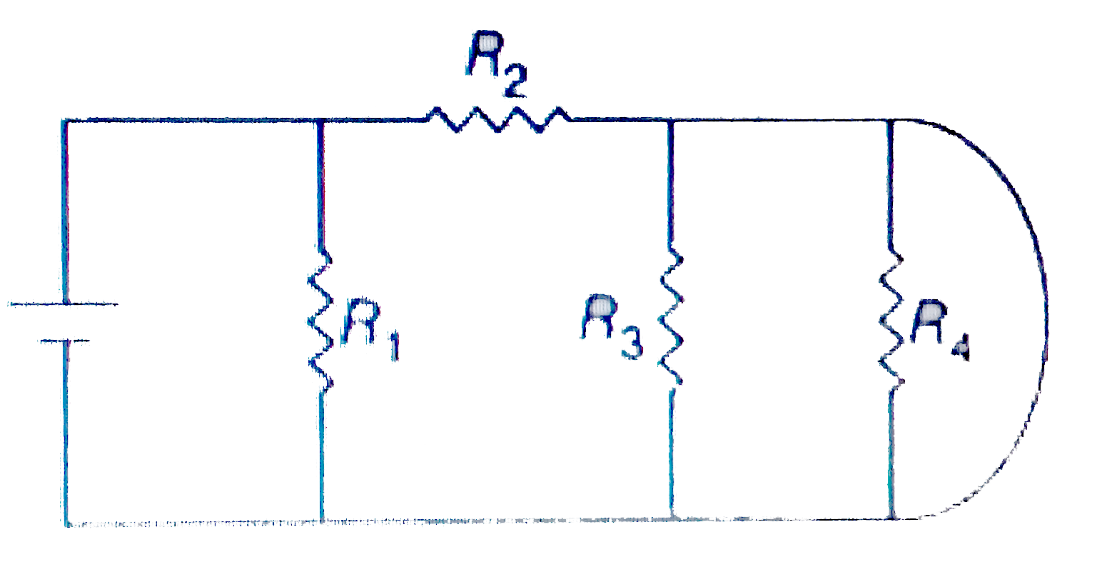 02:18View Solution
If internal resistance of a cell is proportional to current drawn from the cell. Then the best representation of terminal potential difference of a cell with current drawn from cell will be
04:18View SolutionA galvanometer, together with an unknown resistance in series, is connected across two identical batteries of each `1.5 V`. When the batteries are connected in series,the galvanometer records a current of `1 A`, and when the batteries are connected in parallel, the current is `0.6 A`. In this case, the internal resistance of the battery is `1//'**' Omega`.
What is the value of '*'?05:26View SolutionIn the figur shown, the thermal power generated in 'Y' is maximum when `Y = 4 Omega`. Then X is
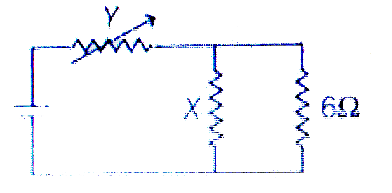 03:45View Solution
A cell of emf E having an internal resistance R varies with R as shown in figure by the curve
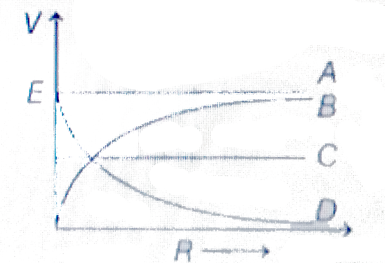 01:08View Solution
Six wires each of resistance r form a tetrahedron. The equivalent resistance between corners 1-2 and 1-3 are respectively
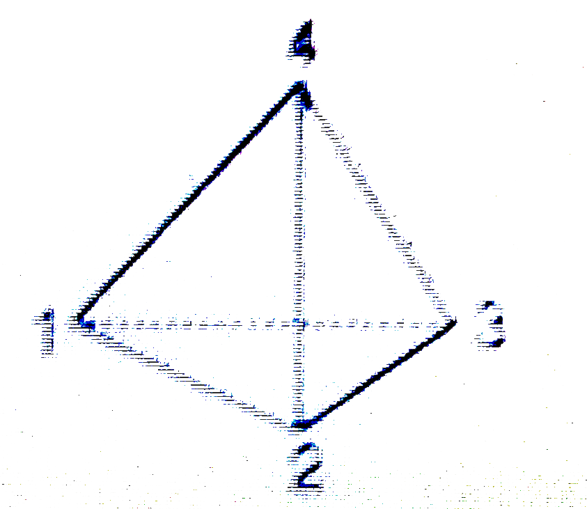 02:33View Solution
A series parallel combination battery consisting of a large number `N = 300` of identical cells, each will an inernal resistance `r = 0.3 Omega`, is loaded with an external resistances `R = 10 Omega`. Find the number `n` of parallel groups consisting of an equal number of cells connected in series, at which the external resistance generates the highest thermal power.
06:31View SolutionOne end of a Nichrome wire of length `2L` and cross-sectional area `A` is attached to an end of another Nichrome wire of length `L` and cross-sectional area `2A`. If the free end of the longer wire is at an electric potential of `8.0` volts, and the free end of the shorter wire is at an electric potential `1.0` volts, the potential at the junction of the two wires is equal to
02:46View SolutionIn the circuit shown, the resistance are given ohms and the battery is assumed ideal with end equal to 3.0 volts. The resistance that dissipates the maximum power is
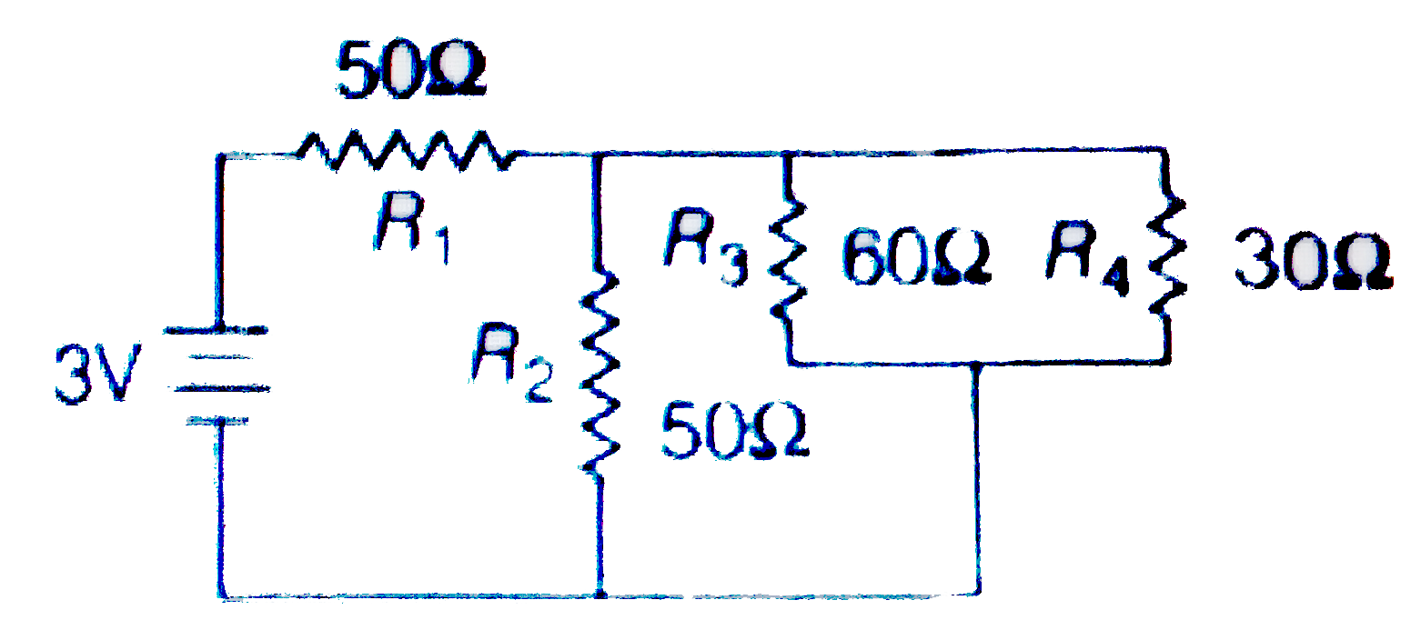 01:18View Solution
In the diagram, resistance between any two junction is R. Equivalent resistance acm terminas A and B is (assume P and Q also as juction)
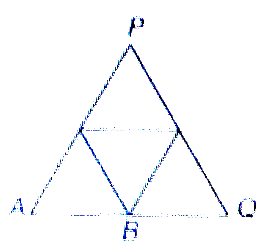 02:12View Solution
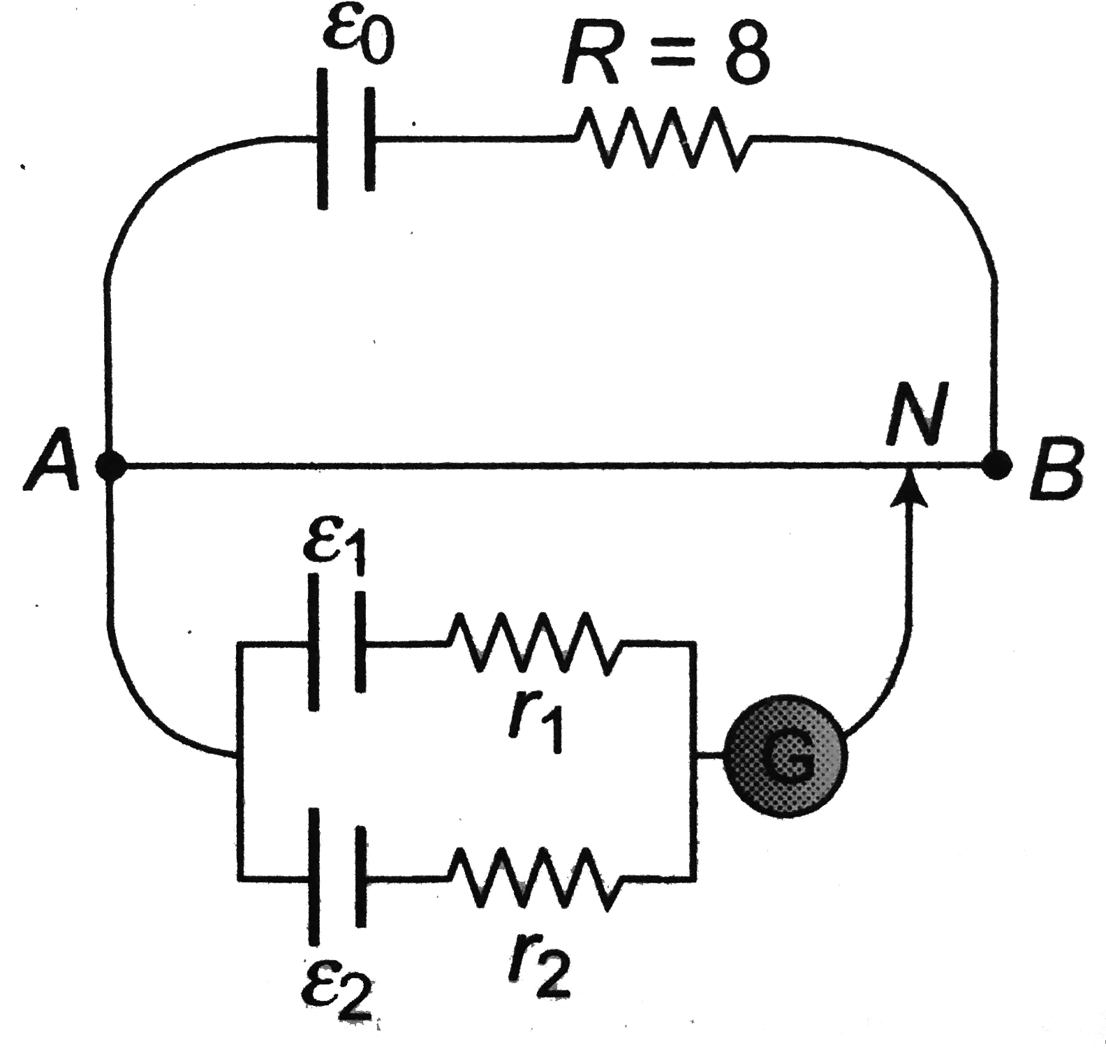
A battery of emf `E_(0) = 12 V` is connected across a `4 m` long uniform wire having resistance `(4 Omega)/(m)`. The cells of small
emfs `epsilon_(1) = 2 V` and `epsilon_(2) - 4 V` having internal resistance `2 Omega` and `6 Omega` respectively, are connected as shown in the figure. If galvanometer shows no deflection at the point `N`, the distance of point `N` from teh point `A` is equal to
 08:12View Solution
In the circuit shown, what is the potential different `V_(PQ)` ?
 04:49View Solution
In an experiment, a graph was plotted of the potential difference V between the terminals of a cell against the circuit current "I" by varying load rheostat, internal conductance of the cell is given by
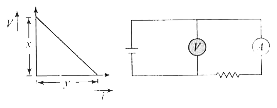 05:45View Solution
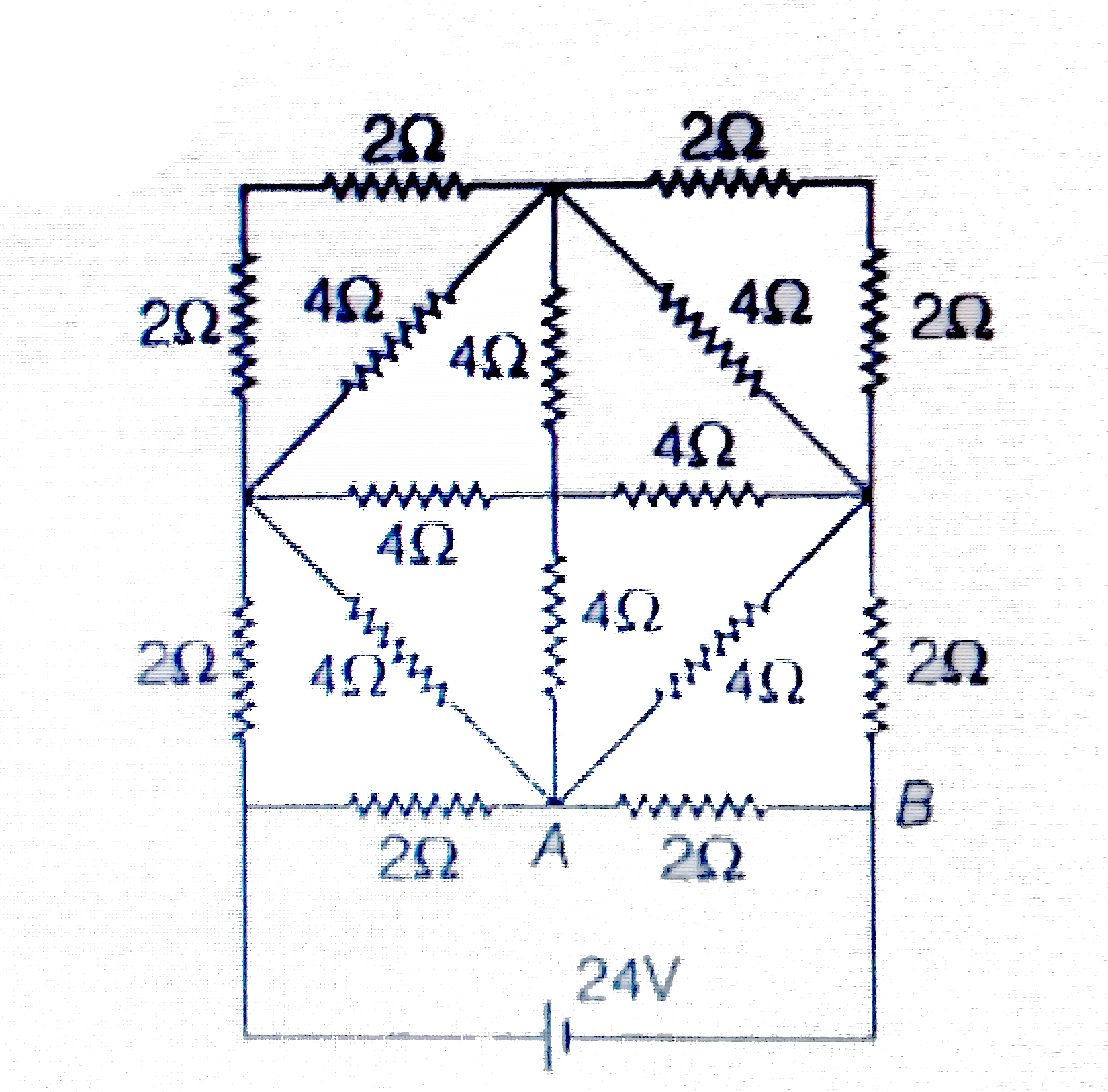
In the circuit, 8 resistors of `2 Omega` and 8 resistors of `4 Omega` are connected as shown in the figure. The current in the branch AB is
 03:02View Solution
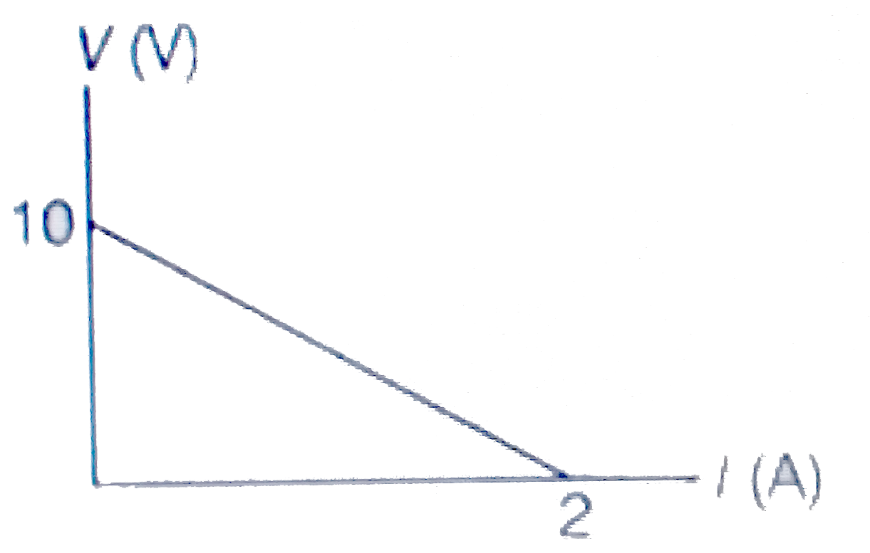
A battery of emf E and internal resistance r is connected across a resistance R. Resistance R can be adjusted to any value greater than or equal to zero. A graph is plotted between the current passing through the resistance (I) and potential difference across the termainals of the battery (V). Maximum power developed across the resistance R is
 02:35View Solution
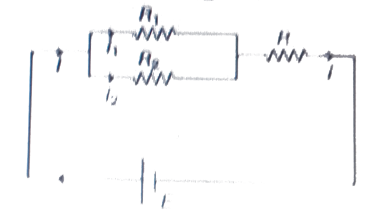
In the circuit shown in figure, the ratio
 01:46View Solution
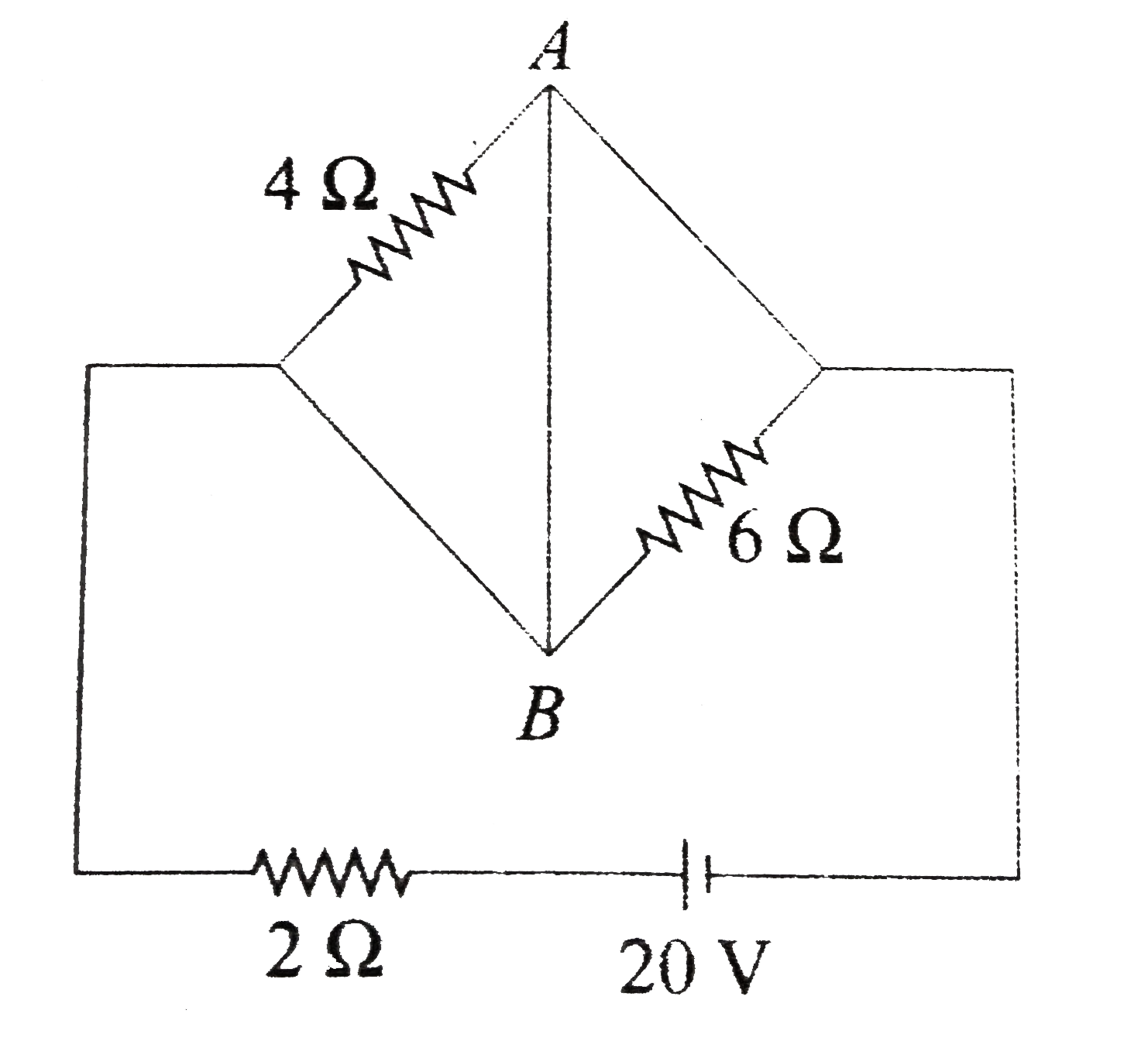
In the circuit shown in figure
 03:13View Solution
A microameter has a resistance of `100 omega` and a full scale range of ` 50 muA`. It can be used as a voltmeter or as a higher range ammeter provides a resistance is added to it . Pick the correct range and resistance combination(s)
03:12View SolutionIn the circuit shown in figure
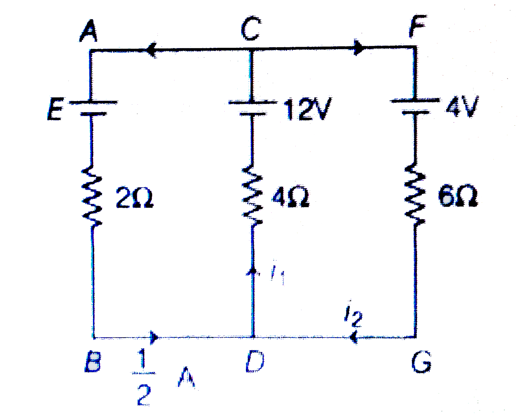 08:33View Solution
A voltmeter reads the potential difference across the terminals of an old battery as `1.40 V`, while a potentiometer reads its voltage to be `1.55 V`. The voltmeter resistance is `280 Omega`.
03:41View SolutionA battery of emf E and internal resistance r is connected across a resistance R. Resistance R can be adjusted to any value greater then or equla to zero. A graph is plotted between the current passing through the resistance (I) and potential (V) across it. Select the correct alternatives.
 08:00View Solution
In the circuit shown in figure
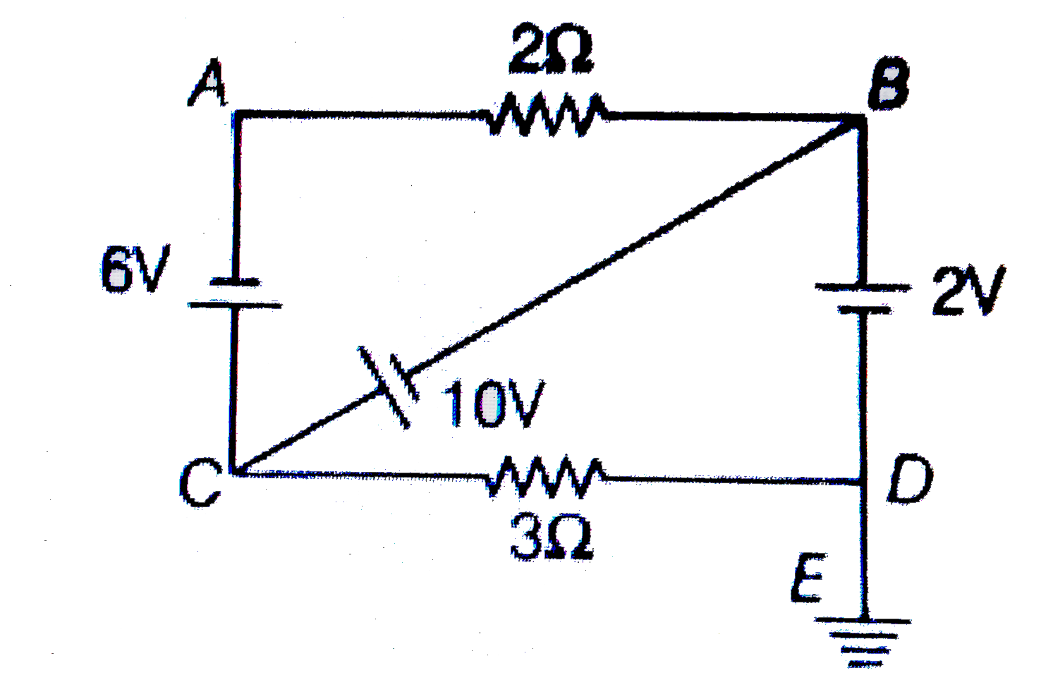 05:40View Solution
Two bulbs consume same energy when operated at `200 V and 300 V` , respectively . When these bulbs are connected in series across a dc source of `500 V`, then
03:54View Solution
All Questions questions and complete solutions for chapter CURRENT ELECTRICITY of DC PANDEY PHYSICS (HINGLISH) of Class 11
