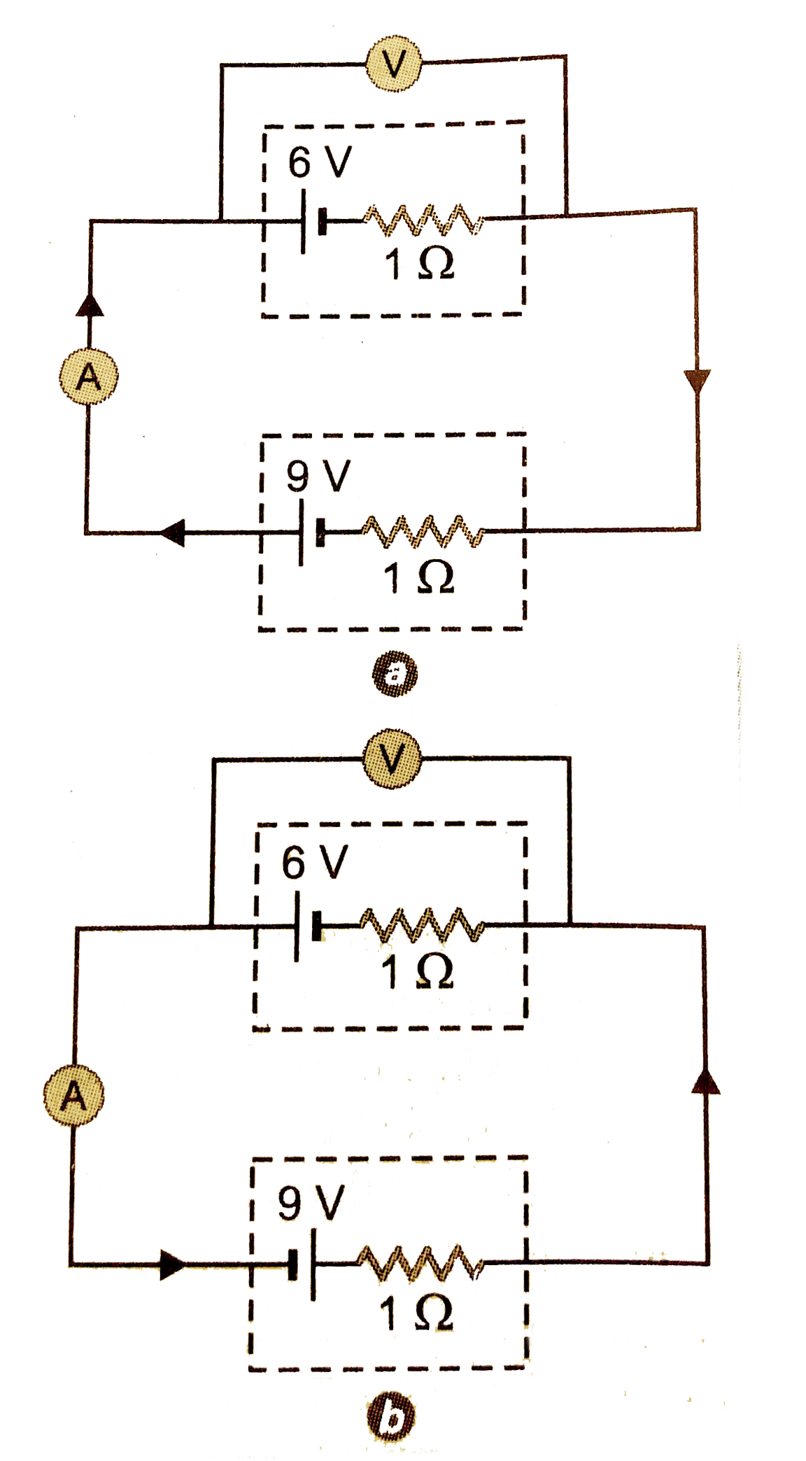
Which of the following wiring diagrams could be used to experimentally determine R using ohm's law? Assume an ideal voltmeter and an ideal ammeter.
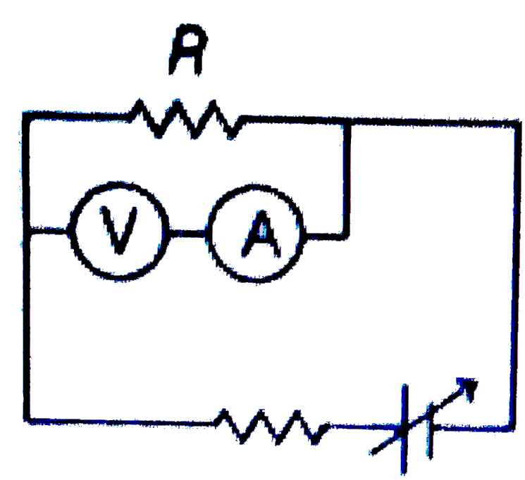
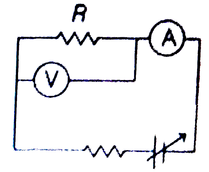
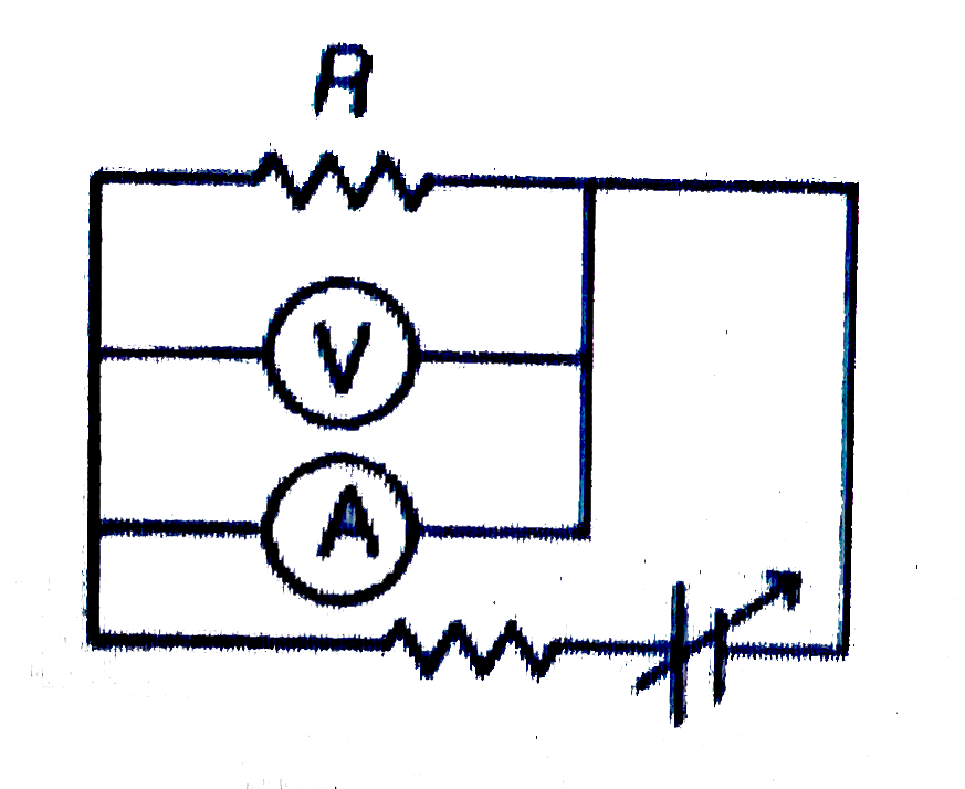
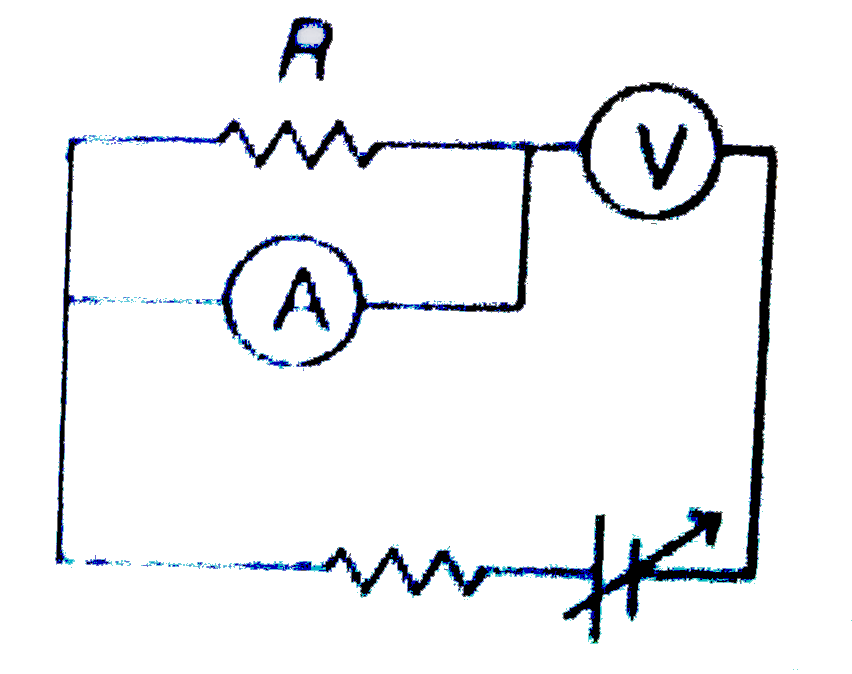
The correct Answer is:B
Step by step video, text & image solution for Which of the following wiring diagrams could be used to experimentally determine R using ohm's law? Assume an ideal voltmeter and an ideal ammeter. by Physics experts to help you in doubts & scoring excellent marks in Class 11 exams.
Updated on:21/07/2023Topper's Solved these Questions
Similar Questions
Knowledge Check
Express which of the following set ups can be used to verify
ohm's law?A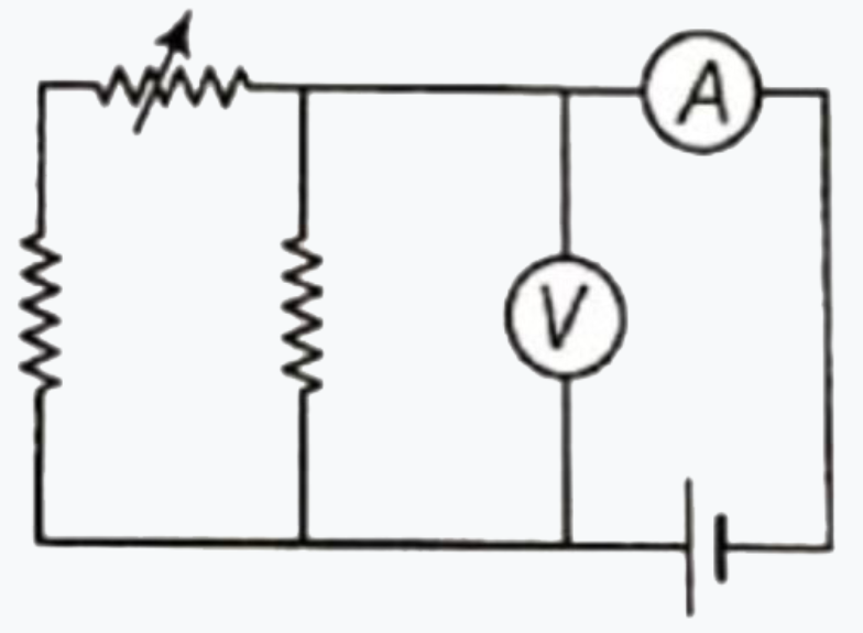 B
B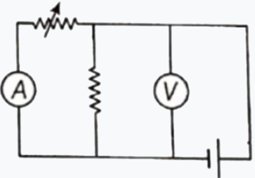 C
C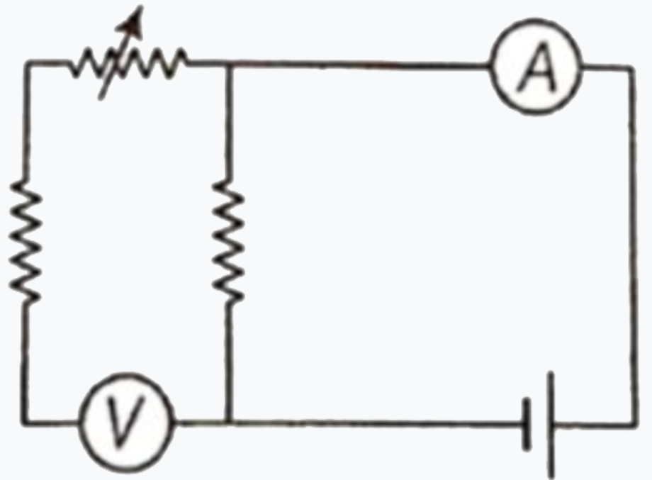 D
D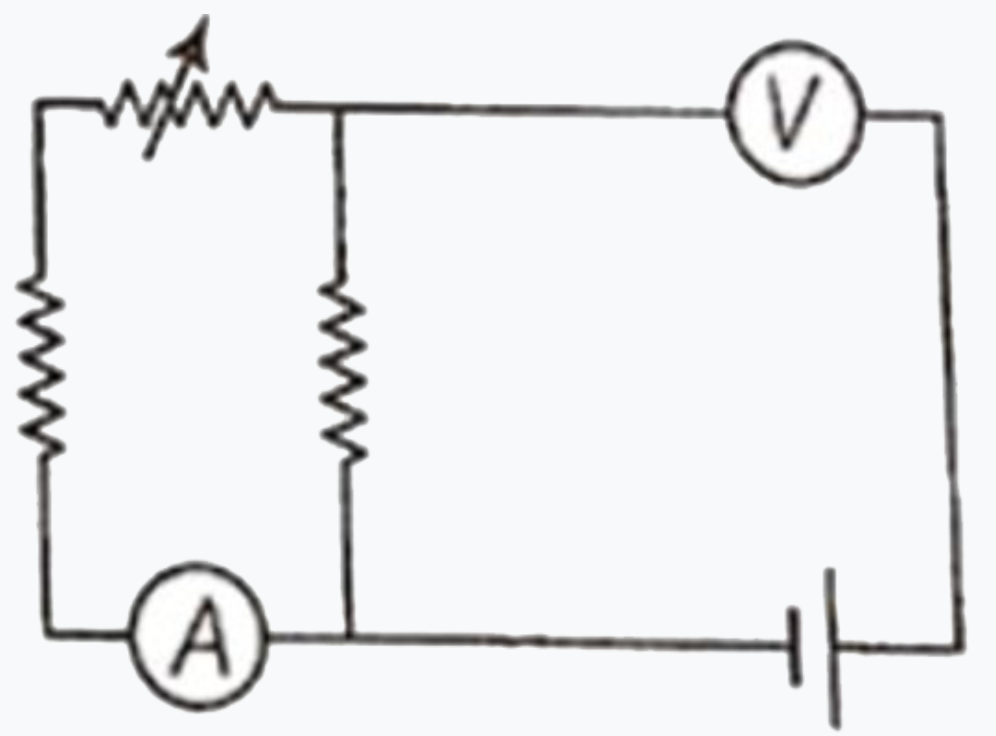
Express which of the following set ups can be used to verify Ohm's law.
A B
B C
C D
D
Express which of the following set ups can be used to verify
ohm's law?A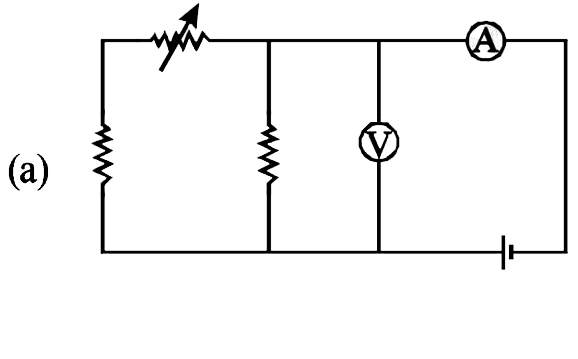 B
B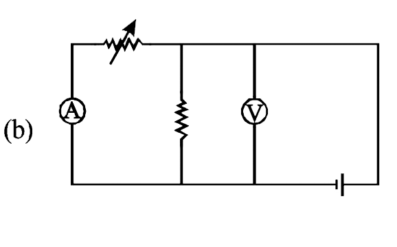 C
C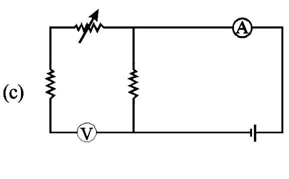 D
D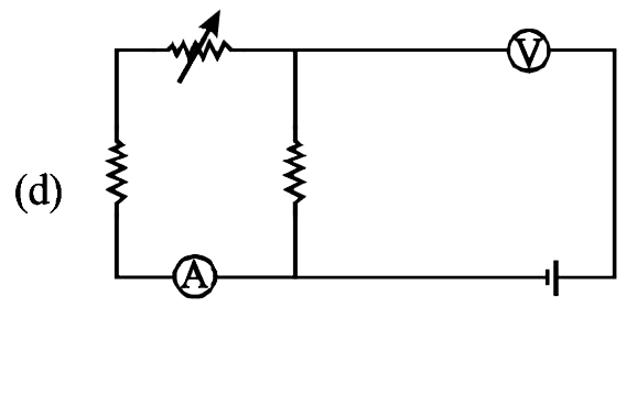
Which of the following diagrams, Fig. depicts ideal gas behaviour ?
View SolutionThe value of current in the following diagram is (diode assumed to be ideal one)
 .
.
View SolutionWhich of the following circuits gives the correct value of resistance, when computed by using R=(V/I) where V and I are voltmeter and ammeter reading, respectively? The meters are not ideal.
View SolutionWhich of the following law is used in the Millikan's method for the determination of charge
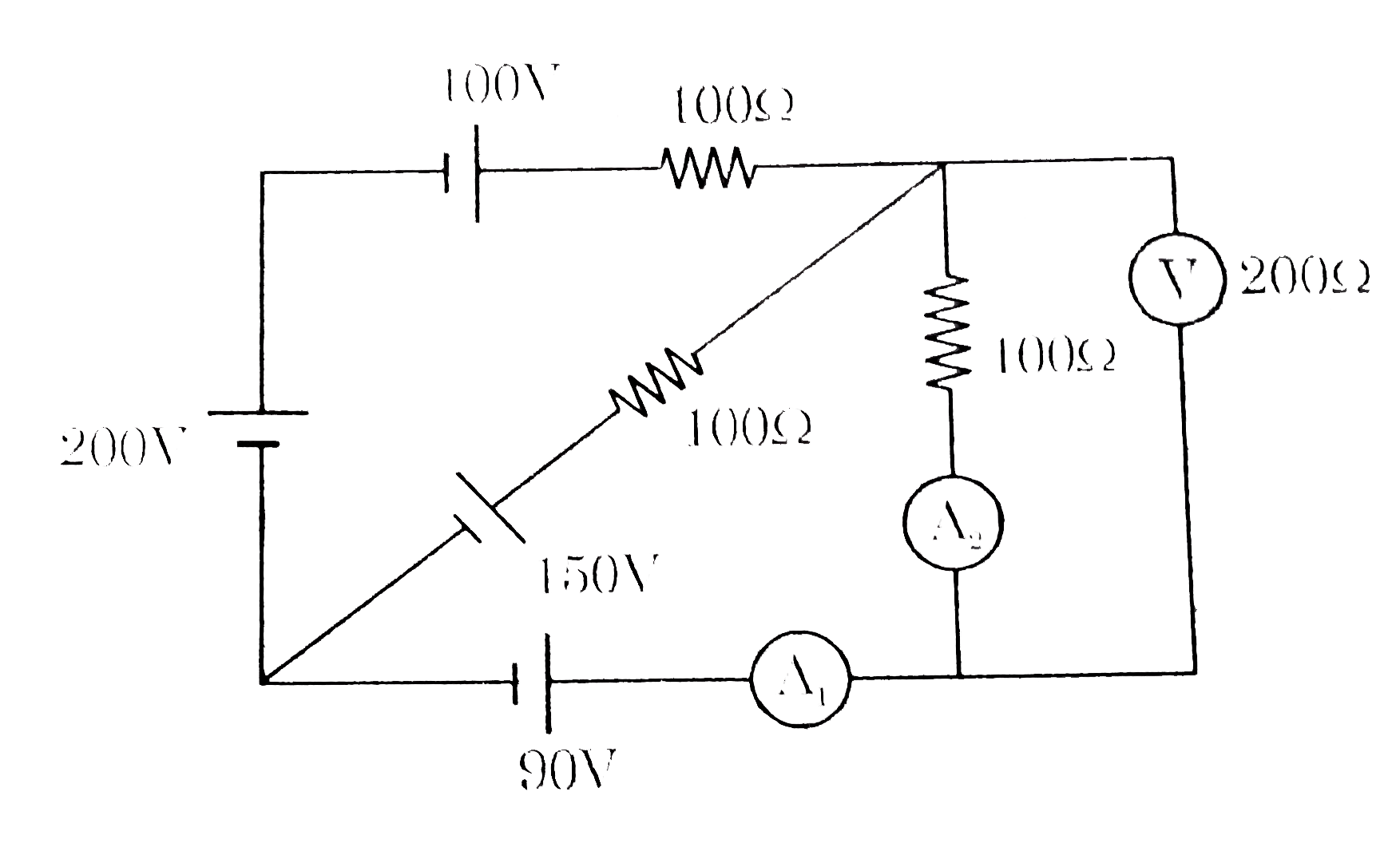
View SolutionWhich of the following options are CORRECT (ammeters are ideal).
View Solution

