Complete Solutions to Kircoff'S Laws And Simple Circuits of chapter CURRENT ELECTRICITY of Class 12 book with complete answers and questions
| Class 12 | PHYSICS |
| Chapter | CURRENT ELECTRICITY |
| A2Z | Kircoff'S Laws And Simple Circuits |
| Number Of Questions | 64 |
| Academic Year | 2023-24 |
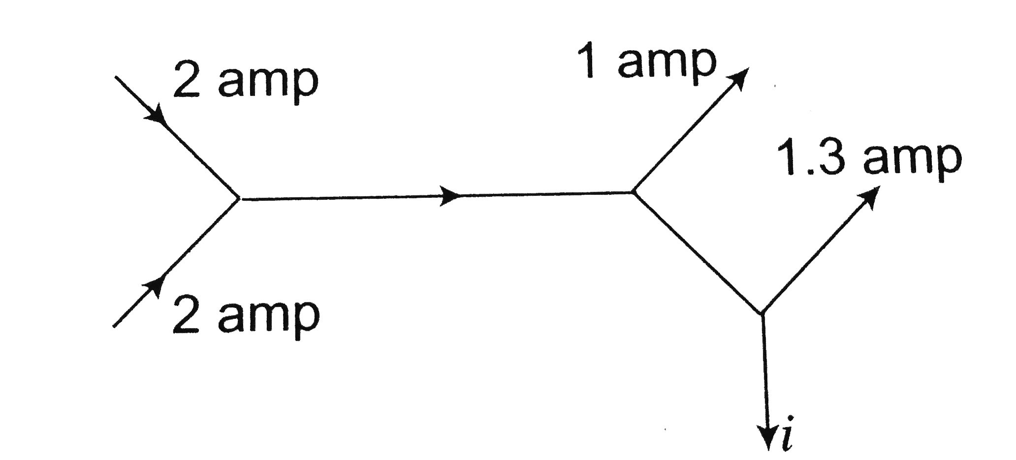
The figure below shows current in a part of electric circuit. The current `i` is
View SolutionA storage battery is connected to a charger for changing with a voltage of 12.5 volts. The internal resistance of the storage battery is `1 Omega`. When the charging current is `0.5 A`, the emf of the storage battery is
View SolutionTo get the maximum current from a parallel combination of `n` identical cells each of internal resistance `r` in an external resistance `R`, when
View SolutionTwo identical calls send the same current in `2 Omega` resistance, whether connected in series of in parallel. The internal resistance of the cell should be
View SolutionThe `n` rows each containing `m` cells in series are joined parallel. Maximum current is taken from this combination across an external resistance of `3 Omega` resistance. If the total number of cells used are 24 and internal resistance of each cell is `0.5 Omega` then
View SolutionWhen a resistance of 2 ohm is connected across terminals of a cell, the current is `0.5 A`. When the resistance is increased to 5 ohm, the current is `0.25 A` The e.m.f. of the cell is
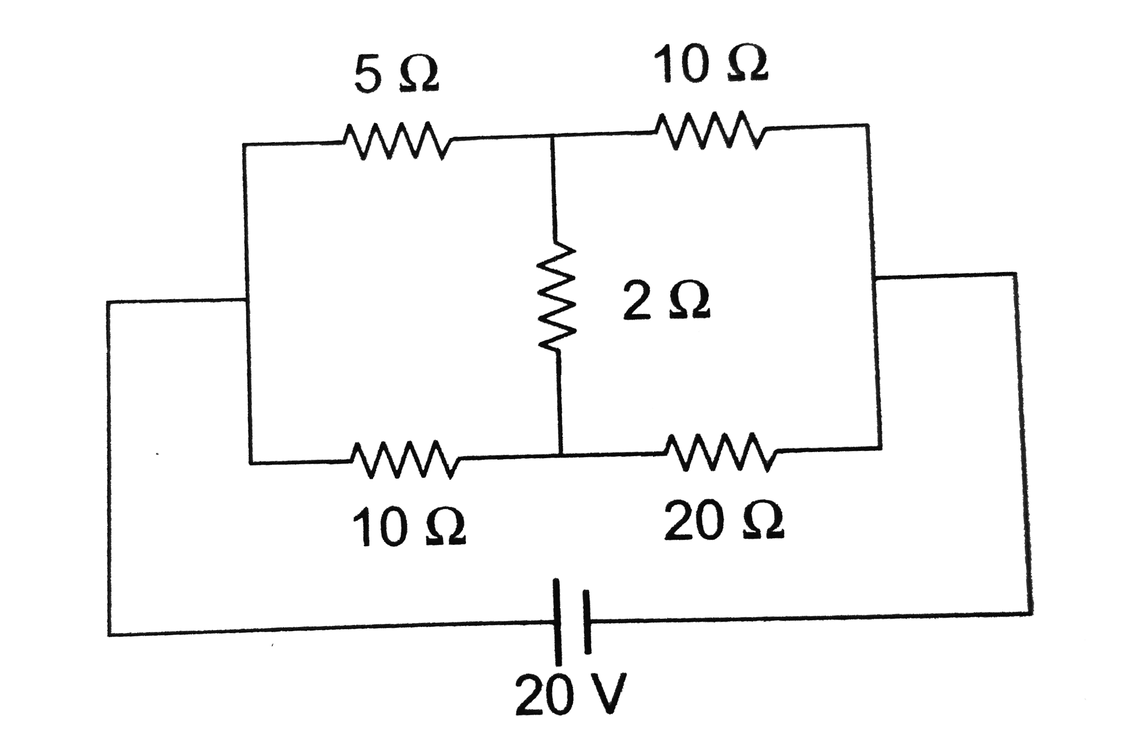
View SolutionIn the given circuit diagram, potential difference across `2 Omega` resistance is
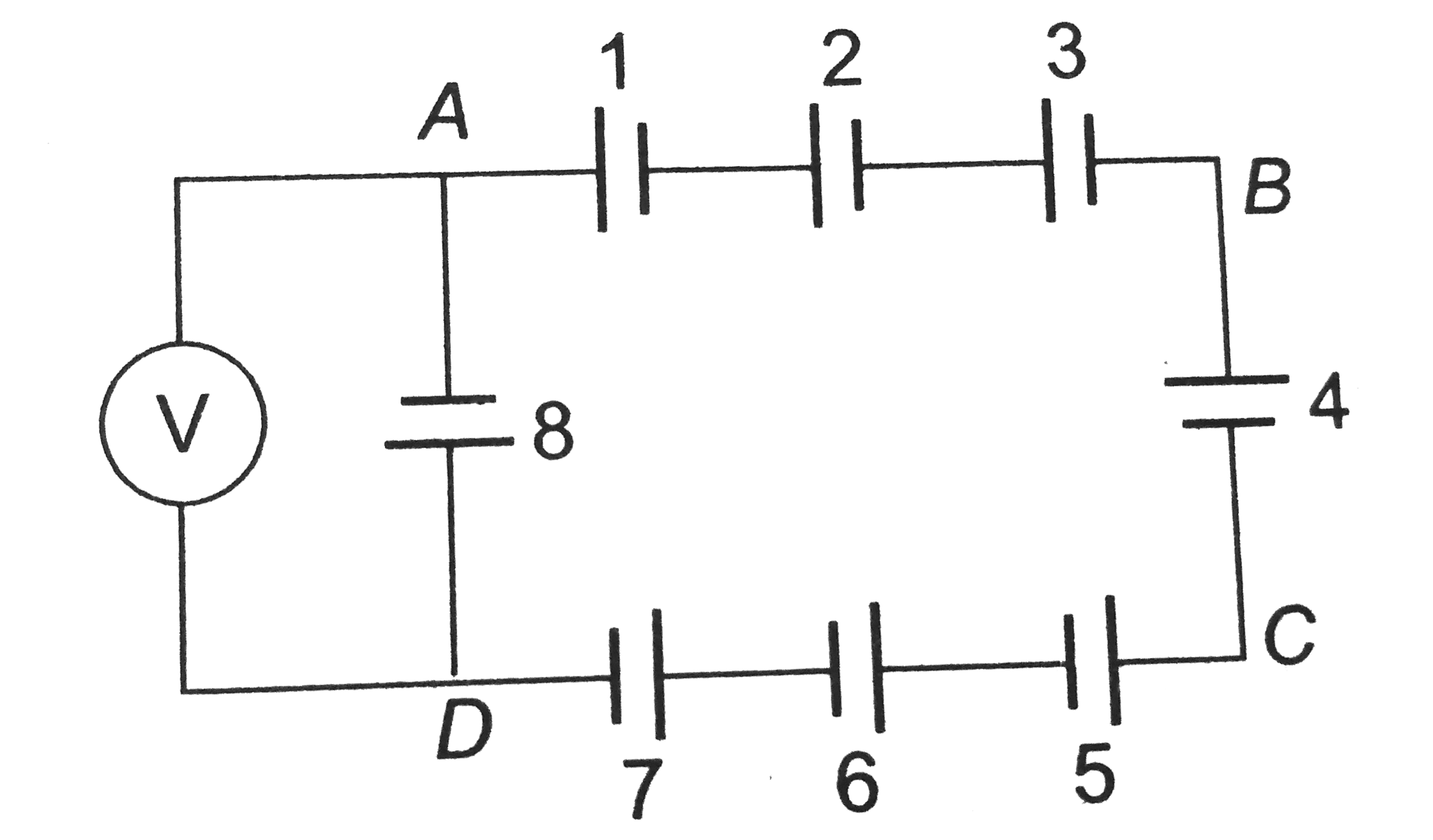
View SolutionEight cells marked 1 to 8, each of emf `5 V` and internal resistance `0.2 Omega` are connected as shown. What is the reading of ideal voltmeter ?
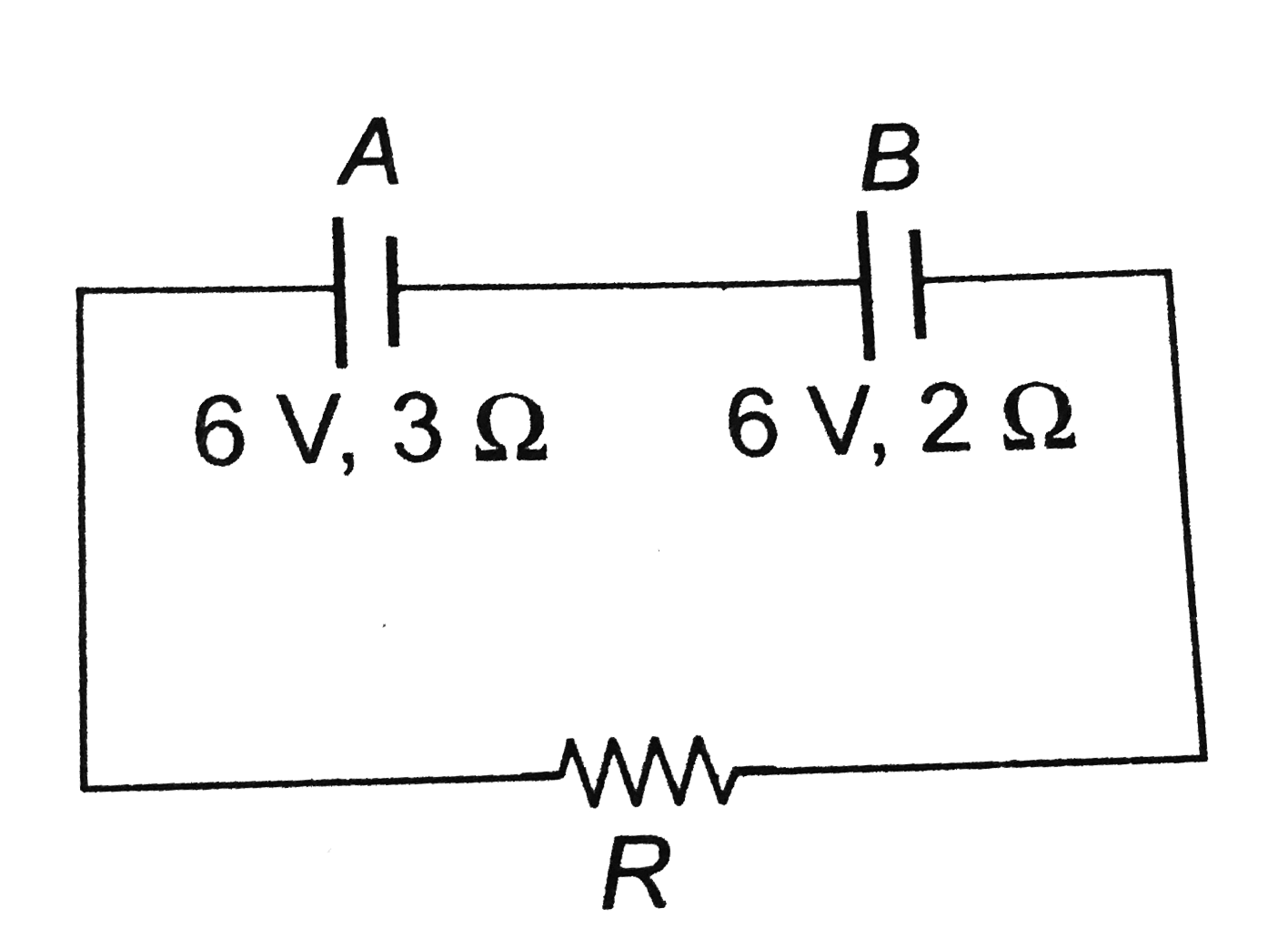
View SolutionTwo sources of emf `6 V` and internal resistance `3 Omega` and `2 Omega` are connected to anexternal resistance `R` as shown. If potential difference across battery `A` is zero, then the value of `R` ( in `Omega`) is
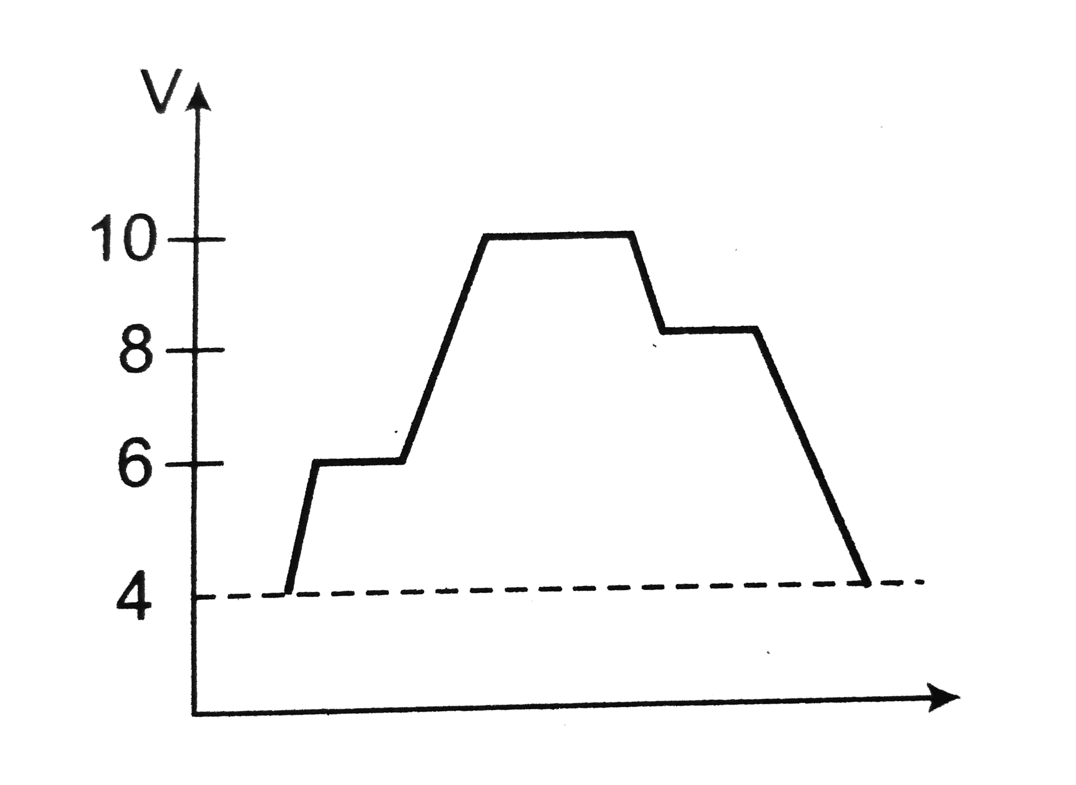
View SolutionThe electric potential variation around a single closed loop contining an ideal battery and one of more resistors is shown in figure. If current of `1 A` flows in the circuit,
View SolutionThe two ends of a uniform conductor are joined to a cell of e.m.f. `E` and some internal resistance. Starting from the midpoint `P` of the conductor, we move in the direction of current and return to `P`. The potential `V` at every point on the path is plotted against the distance covered `(x)`. which of the follwoing graphs best represent the resulting curve ?
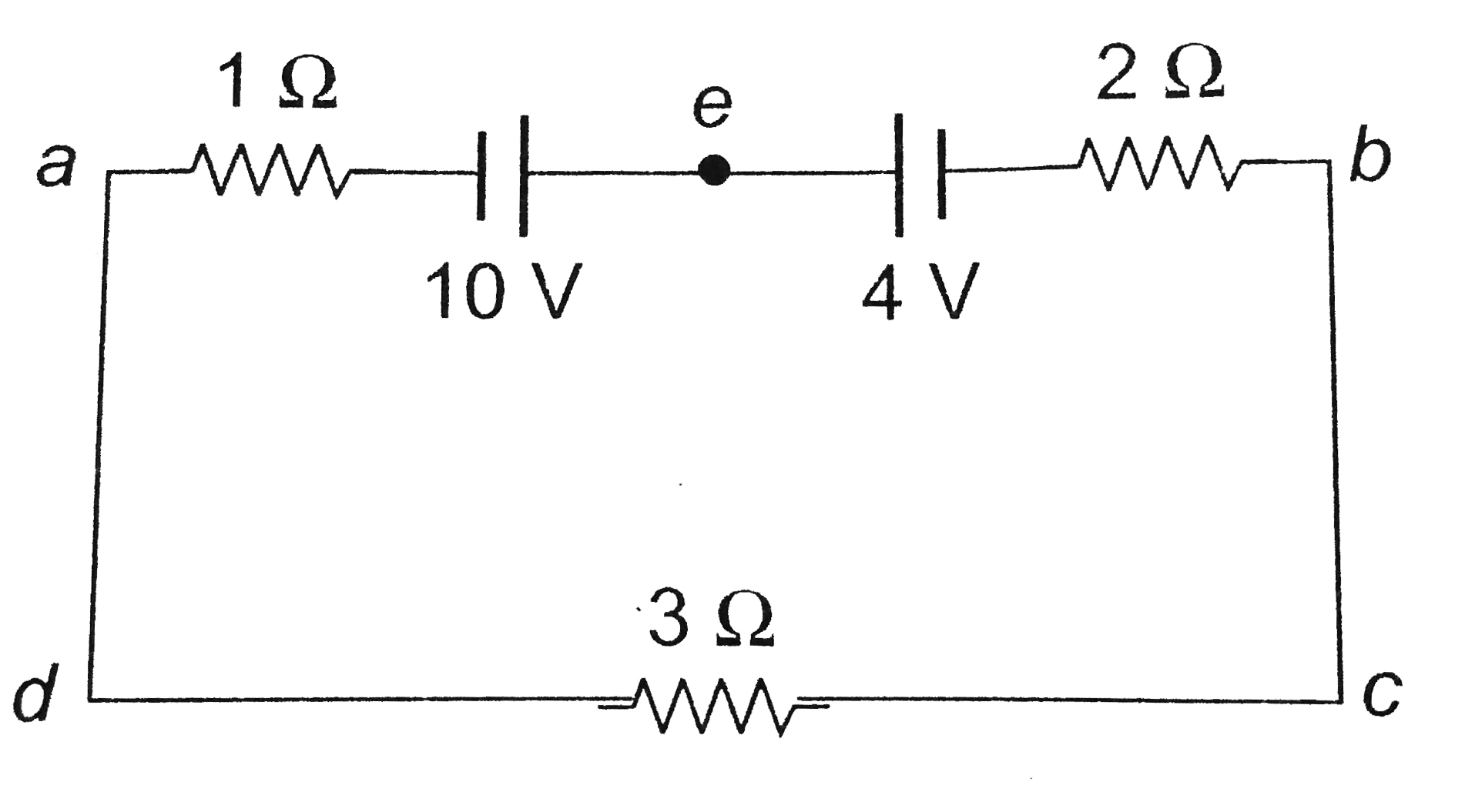
View SolutionThe magnitude and direction of the current in the circuit shown will be
View SolutionTwo batteries each of `E` and internal resistance `r` are connected turn by turn in series and in parallel, and are used to find current in an external resistance `R`. If the current in series is equal to that in parallel, the internal resistance of each battery is
View Solution`N` identical cells, each emf `E` and internal resistance `r` are joined in series. Out of `N` cells, `n` cells are wrongly connected i.e., their terminals are connected in reverse of the required for series connection `(n lt (N)/(2))`. Let `E_(0)` be the emf of resulting battery and `r_(0)` be its internal resistance. Then
View Solutionn identical calls are joined in series with its two cells `A` and `B` in loop with reversed polarities. `EMF` of each shell is `E` and internal resistance `r`. Potential difference across cell `A` or `B` is (here `n gt 4`)
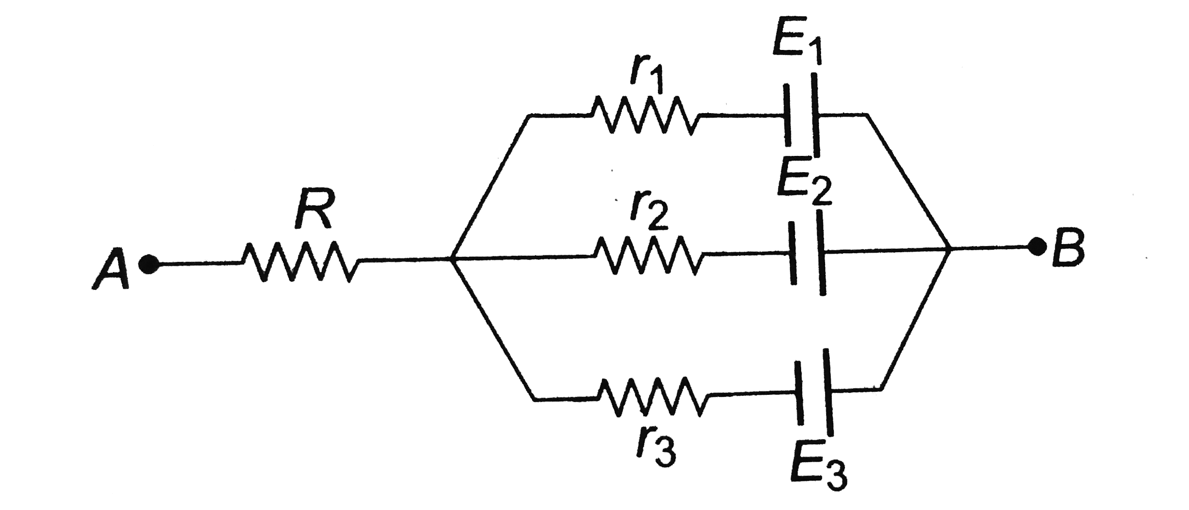
View SolutionIn the network shown the potential difference between `A` and `B` is `(R = r_(1) = r_(2) = r_(3) = 1 Omega, E_(1) = 3V, E_(2) = 2V, E_(3) = 1V`)
View SolutionA battery consists of a variable number `n` of identical cells having internal resistance connected in series. The terminals of the battery are short circuited and the current `I` measured. Which one of the graph below shows the correct relationship between `I` and `n`?
View SolutionIn previous problem, if the cell had been connected parallel (instead of in series) Which of the above graphs would have shown the relationship between total current `I` and `n`?
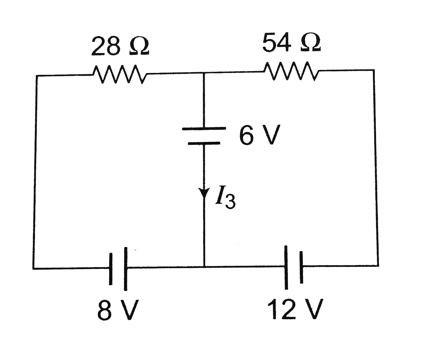
View SolutionConsider the circuit shown in the figure. The current `I_(3)` is equal to
View SolutionIn the circuit element given here, if the potential at point `B = V_(B) = 0`, then the potentials of `A` and `D` are given as

View SolutionIn the given circuit if `I_(1)` and `I_(2)` be the current in resistance `R_(1)` and `R_(2)` respectively then:
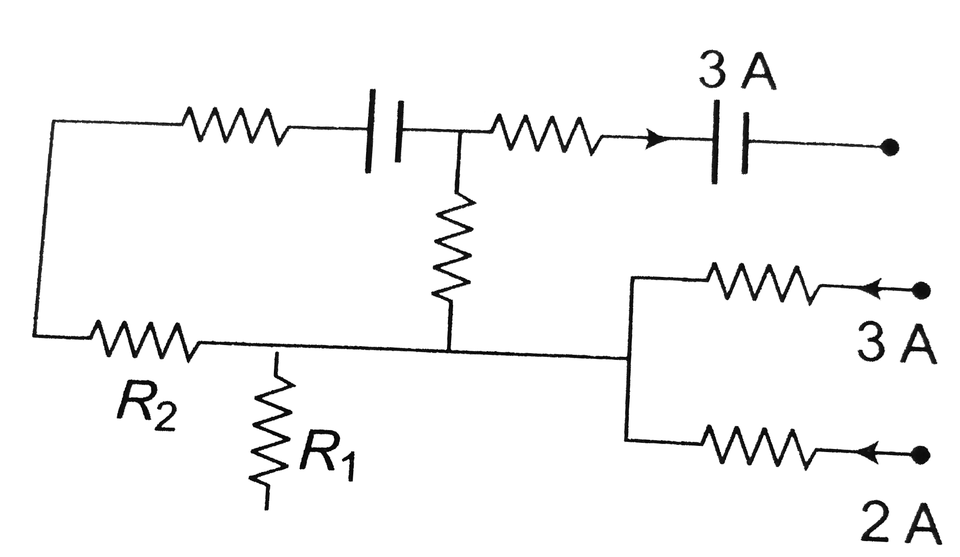
View SolutionThe potential difference between points `A` and `B` adjoining figure is
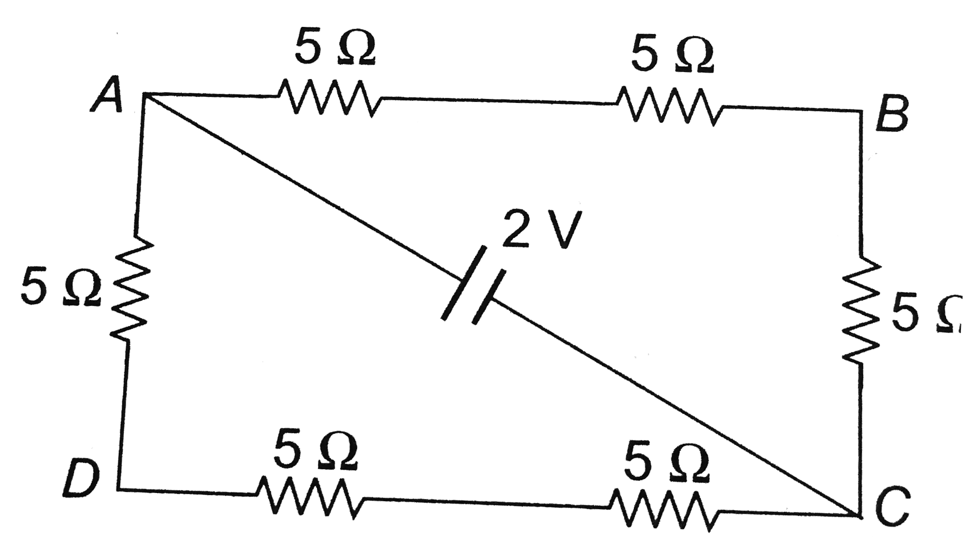
View SolutionThe current in the adjoining circuit will be
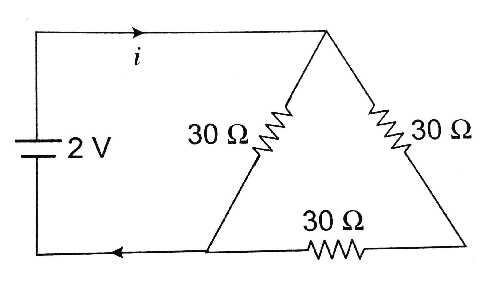
View SolutionThe reading of the ammeter as per figure shown is
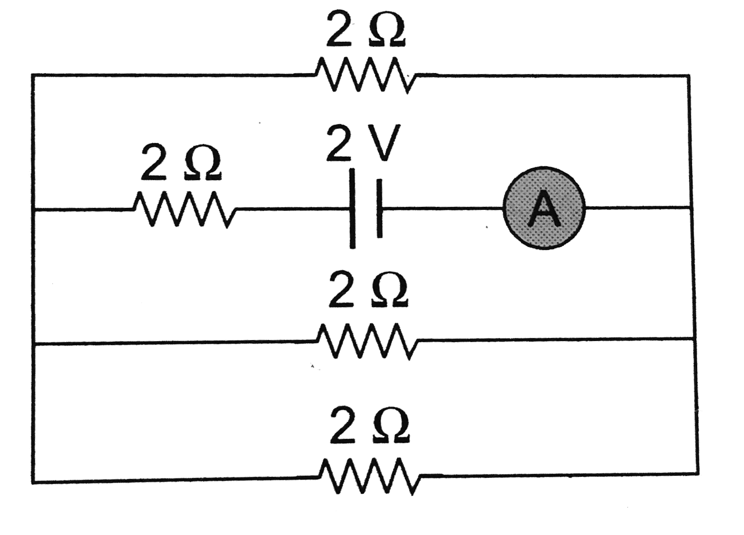
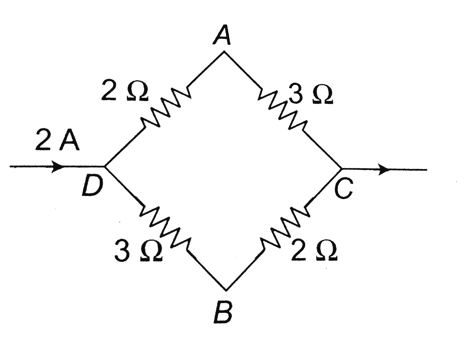
View SolutionA current of `2 A` flows in a system of conductor as shown. The potential difference `(V_(A) - V_(B))`
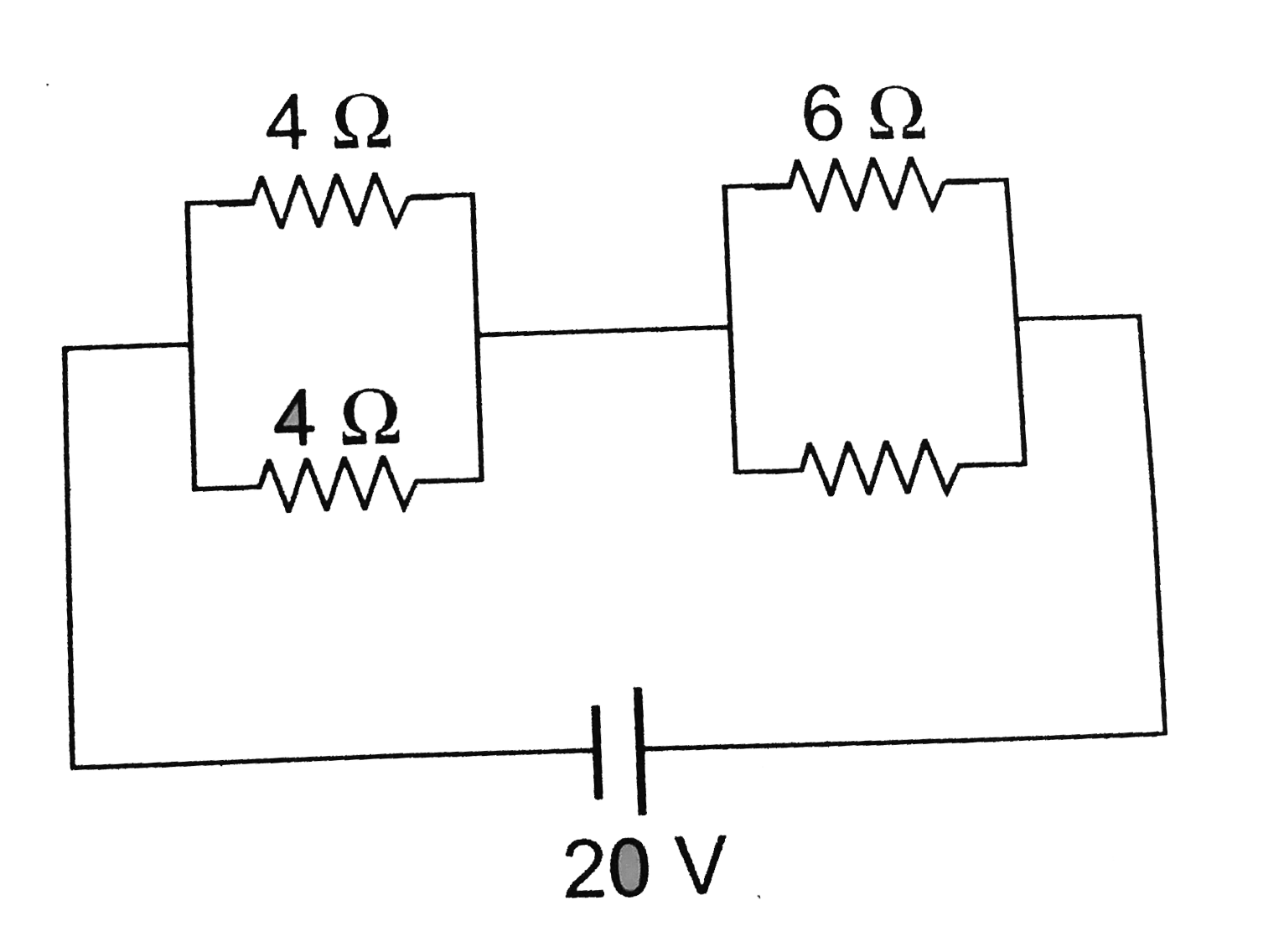
View SolutionFour resistances are connected in a circuit in the given figure. The electric cirrent flowing through `4 ohm` and `6 ohm` resistance is respectively
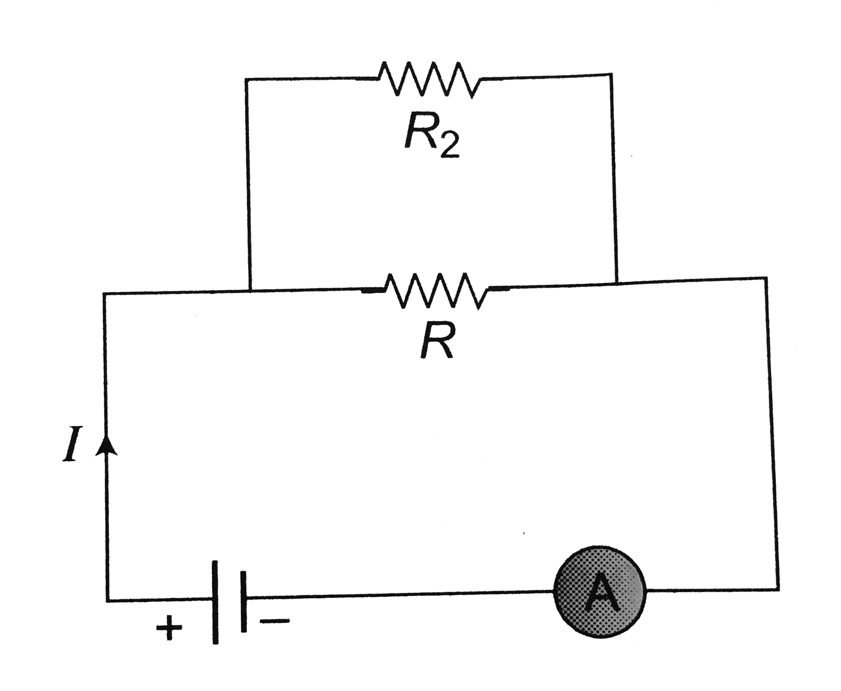
View SolutionIf a resistance`R_(2)` is connected in parallel with the resistance `R` in the circuit shown, then possible value of current through `R` and the possible value of `R_(2)` will be
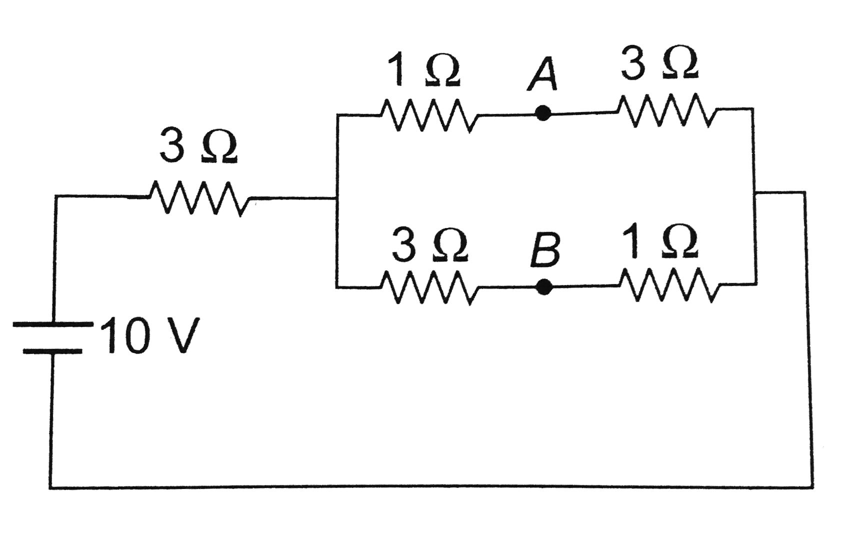
View SolutionA battery of e.m.f. `10 V` is connected to resistance as shown in figure. The potential difference `V_(A) - V_(B)` between the point `A` and `B` is
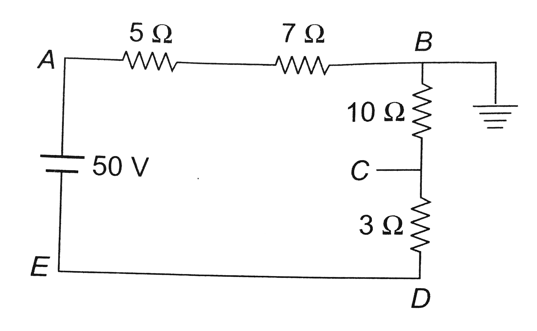
View SolutionIn the circuit shown, the point `B` is earthed. The potential at the point `'A'` is
View SolutionThree resistors each of `4 Omega` are connected together to form a network. The equivalent resistance of the network cannot be
View SolutionIn the circuit shown below, the cell has an e.m.f. of `10 V` and internal resistance of `1 ohm`. The other resistances are shown in the figure. The potential difference `V_(A) - V_(B)` is
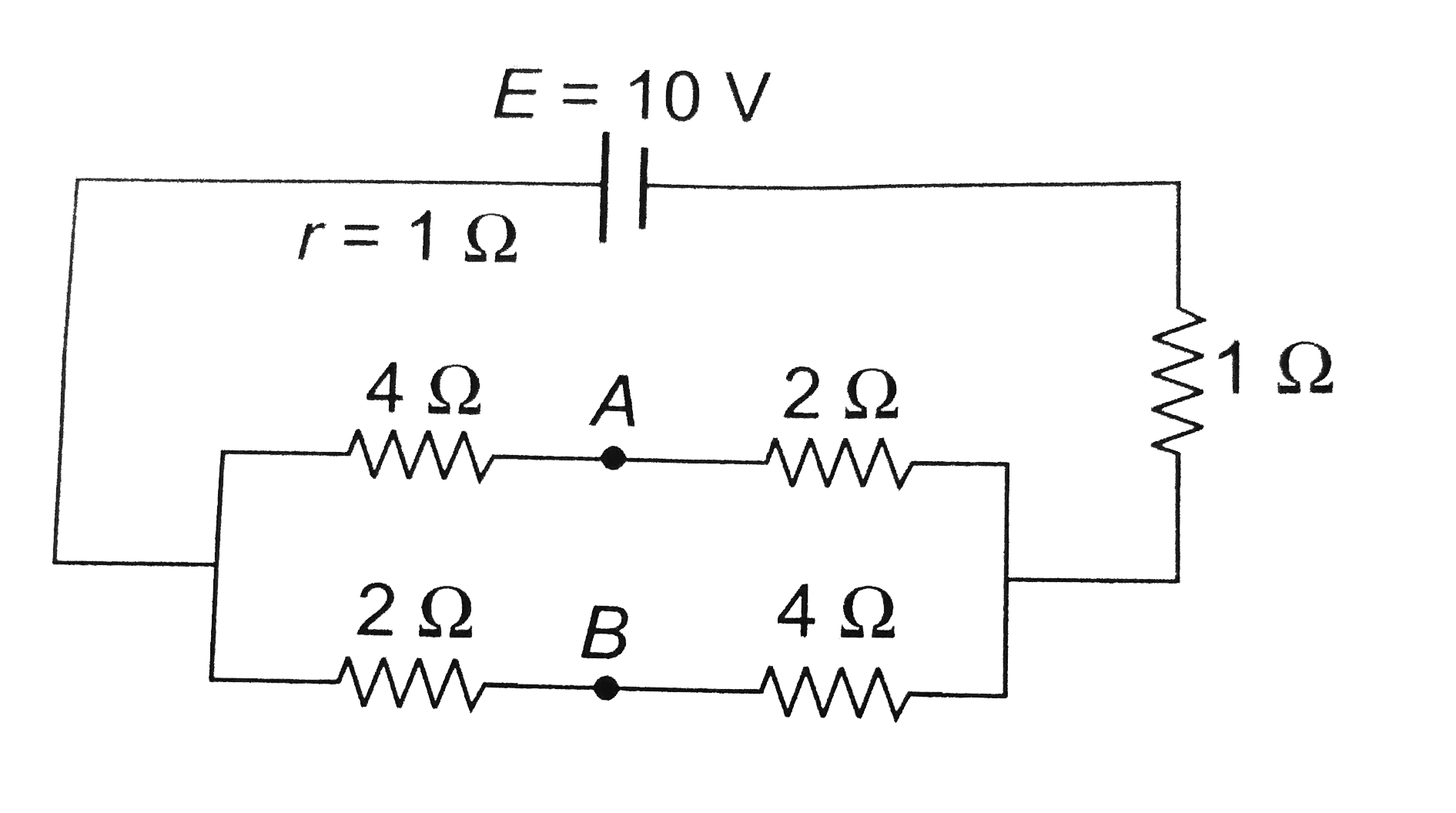
View SolutionThe potential drop across the `3 Omega` resistor is
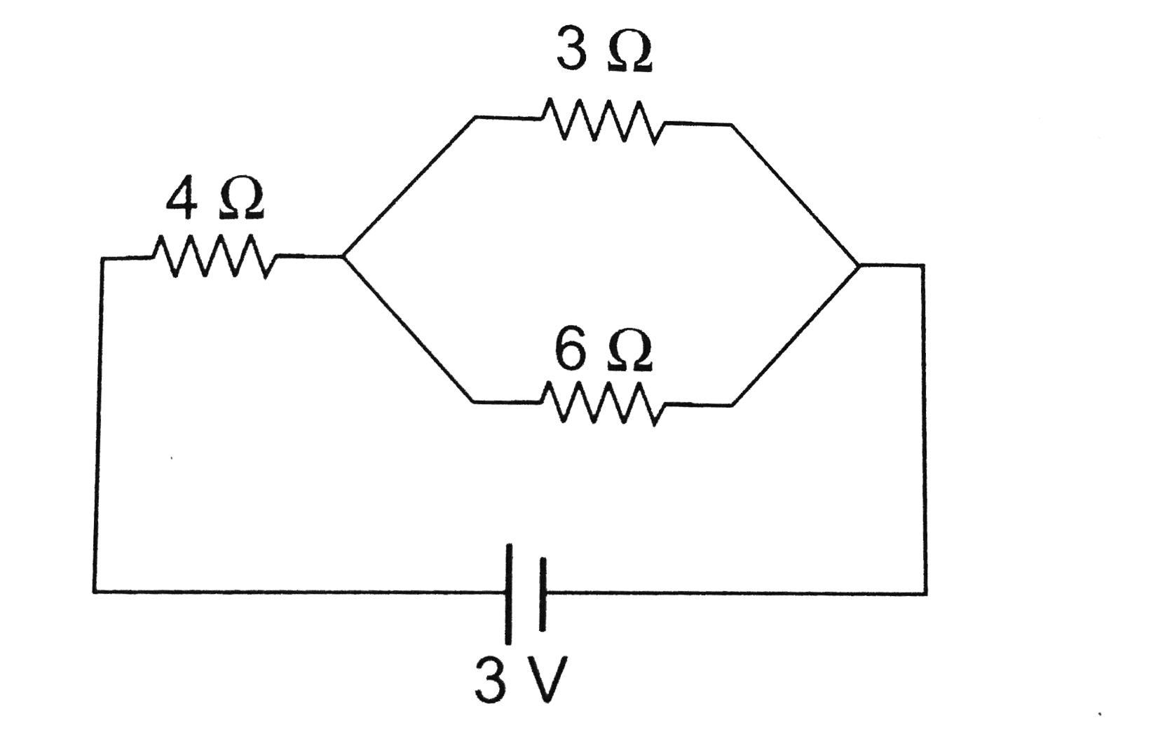
View SolutionA uniform wire of resistance `9 Omega` is cut into 3 equal parts. They are connected in form of equilateral triangle `ABC`. A cell of e.m.f. `2V` and negligible internal resistance is connected across `B` and `C`. Potential difference across `AB` is
View SolutionIn the circuit shown in the adjoining figure, the current between `B` and `D` is zero, the unknown resistance of
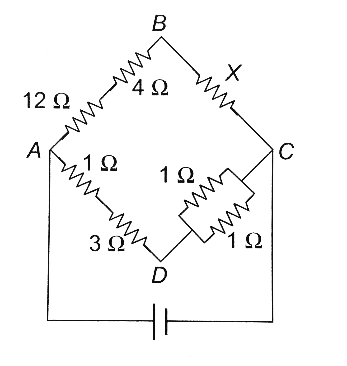
View SolutionIn the figure given the value of X resistance will be, when the p.d. between `B` and `D` is zero
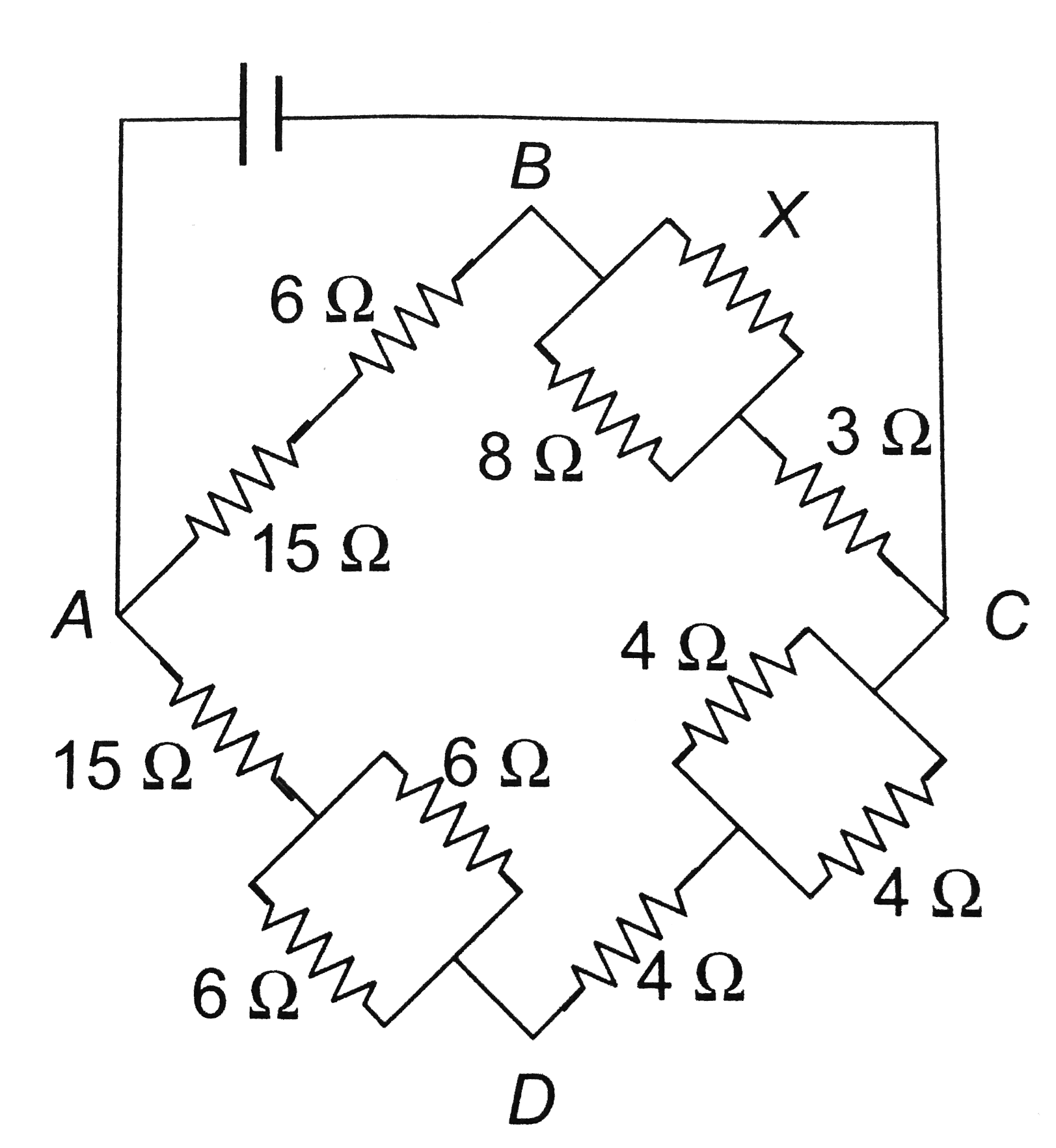
View SolutionFor what value of unknown resistance `X`, the potential difference between `B` and `D` will be zero in the circuit shown in the figure ?
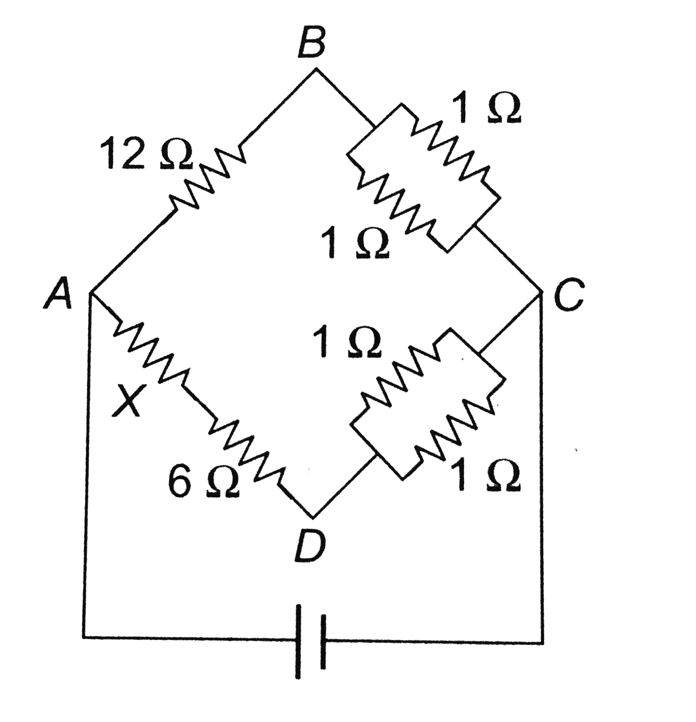
View SolutionIn circuit shown below, the resistance are given in ohms and the battery is assumed ideal with emf equal to 3 volt The voltage across the resistance `R_(4)` is
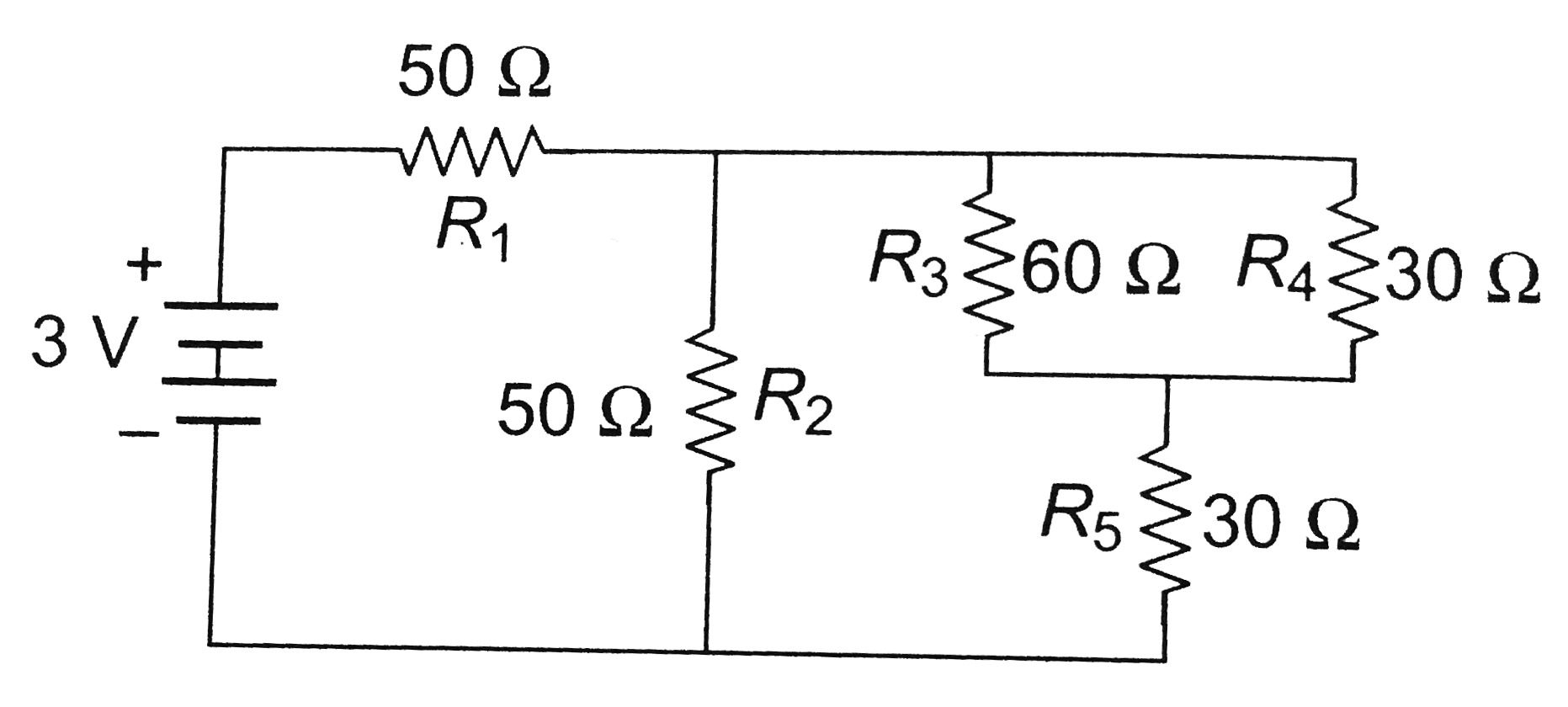
View SolutionTwo batteries of e.m.f. `4V` and `8V` with internal resistances `1 Omega` and `2 Omega` are connected in a circuit with a resistance of `9 Omega` as shown in figure. The current and potential difference between the points `P` and `Q`
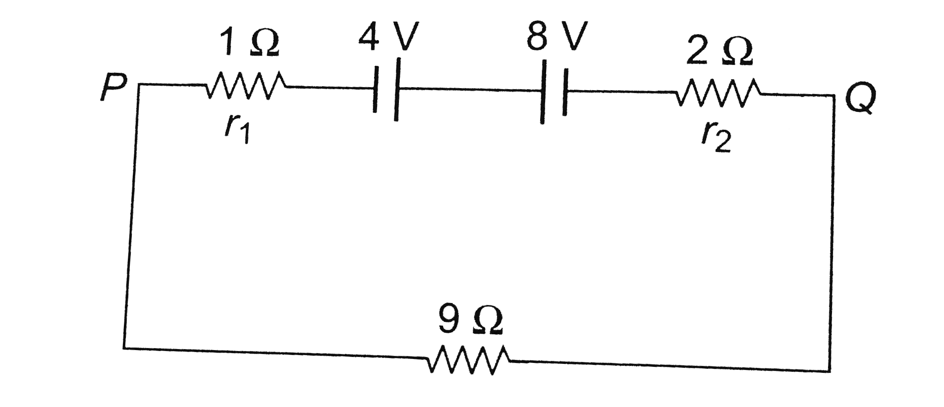
View SolutionFor what value of `R` (in `Omega`) in circuit, current through `4 Omega` resistance is zero ?
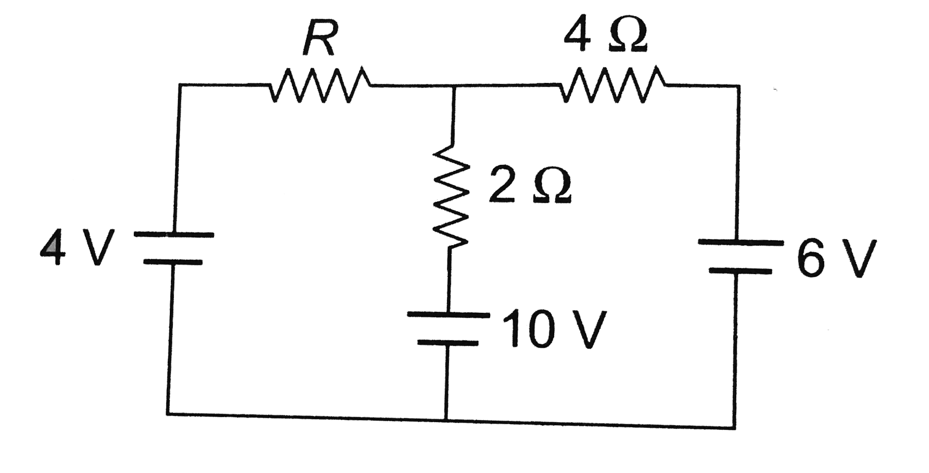
View SolutionFind current in the branch `CD` of the circuit
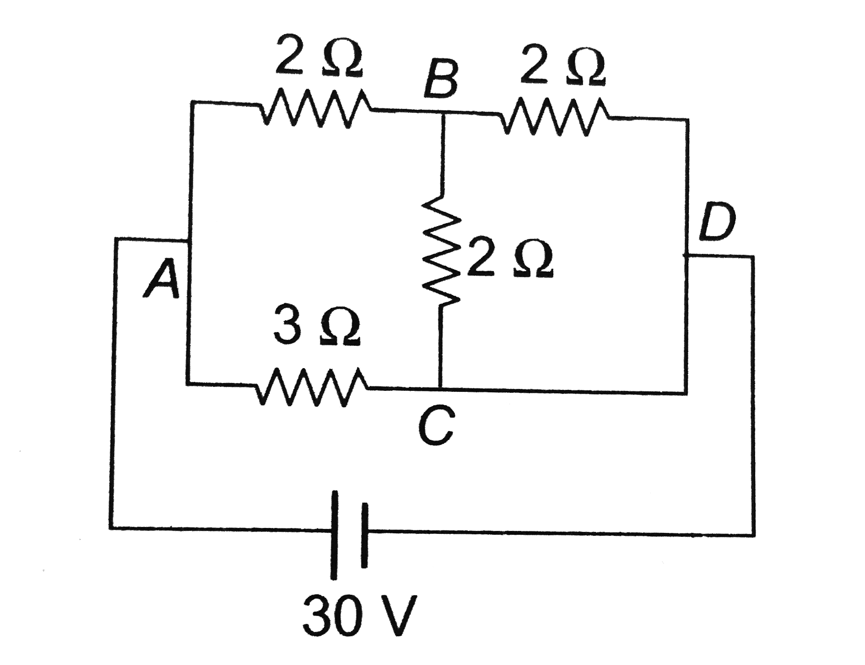
View SolutionIn the circuit shown, calculate the current through `6V` battery
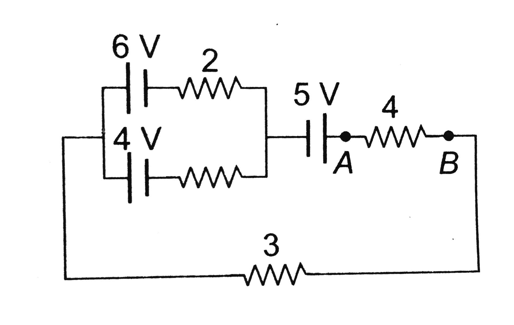
View SolutionFind the value of `R` for which no current will flow through `5V` battery
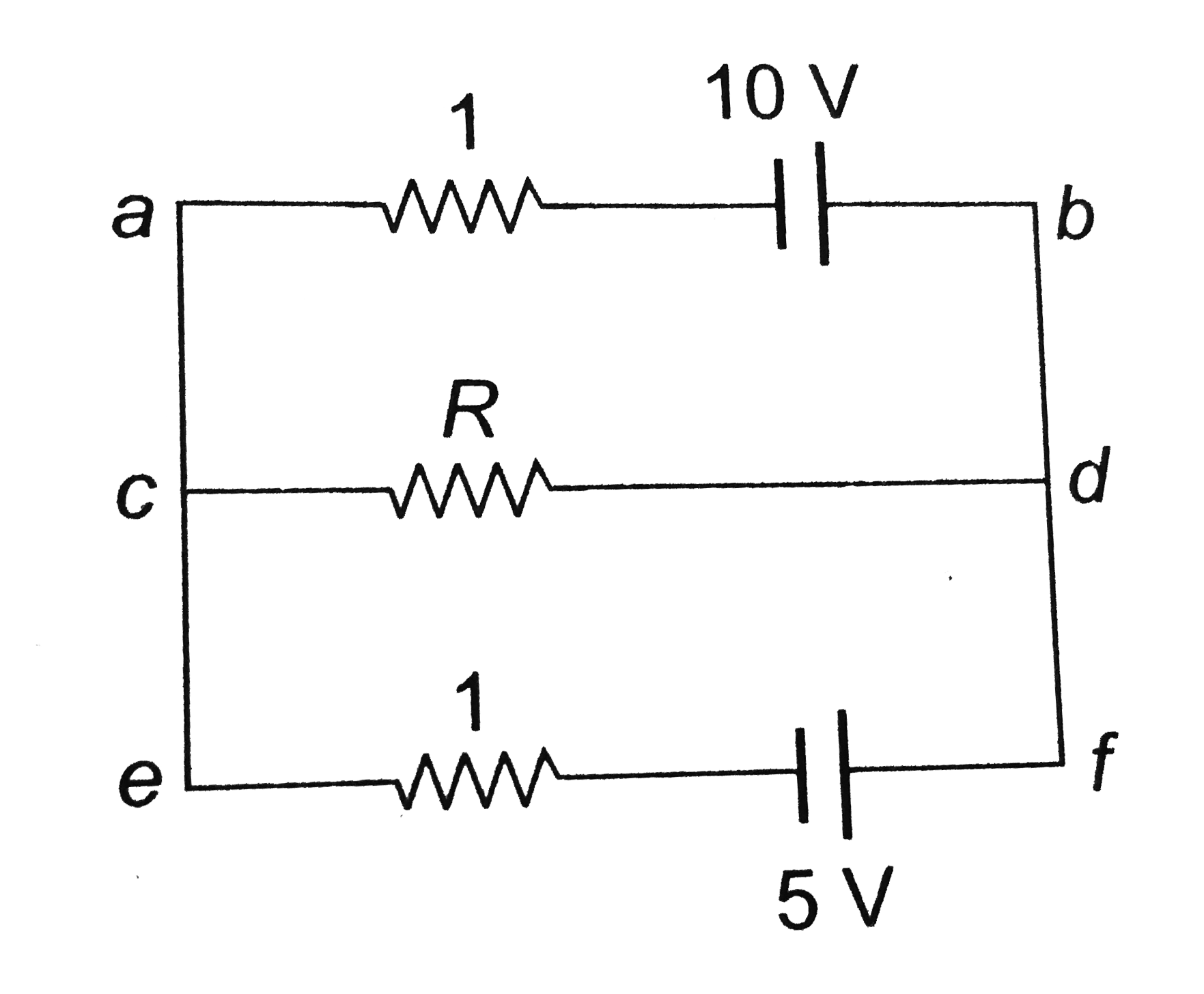
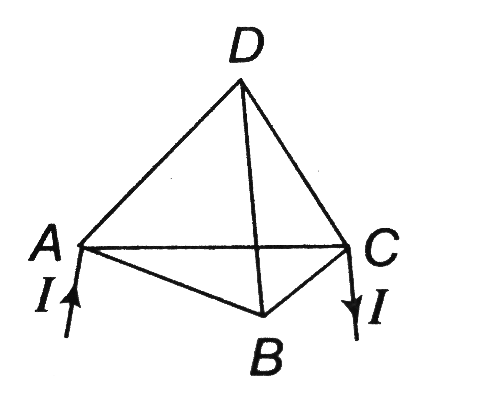
View SolutionA wire frame in the from of a tetrahedron `ABCD` is connected to a battery. The resistance of all the edges of the tetrahedom is equal. Indicate the edges of the frame whose removal does not affect `I` at all
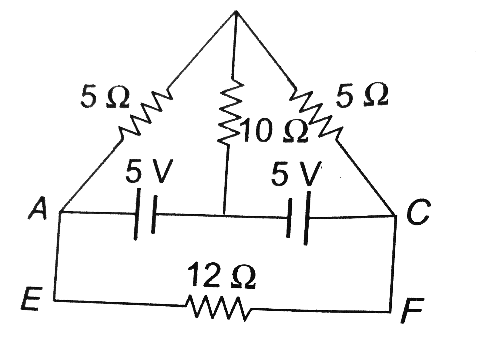
View SolutionIn the circuit of adjoining figure the current through `12 Omega` resister will be
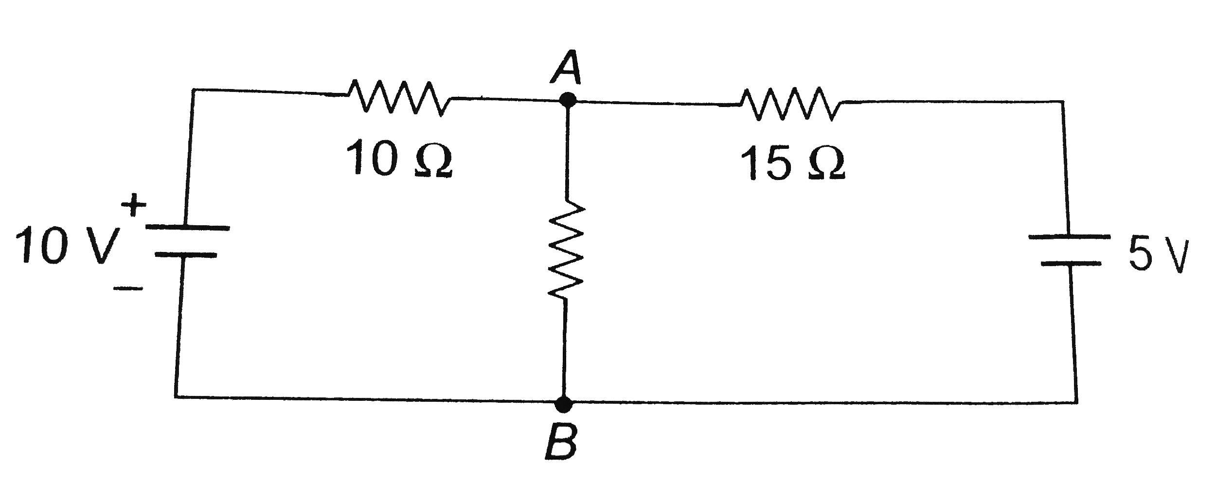
View SolutionA circuit is arranged as shown. Then, the current from `A` to `B` is
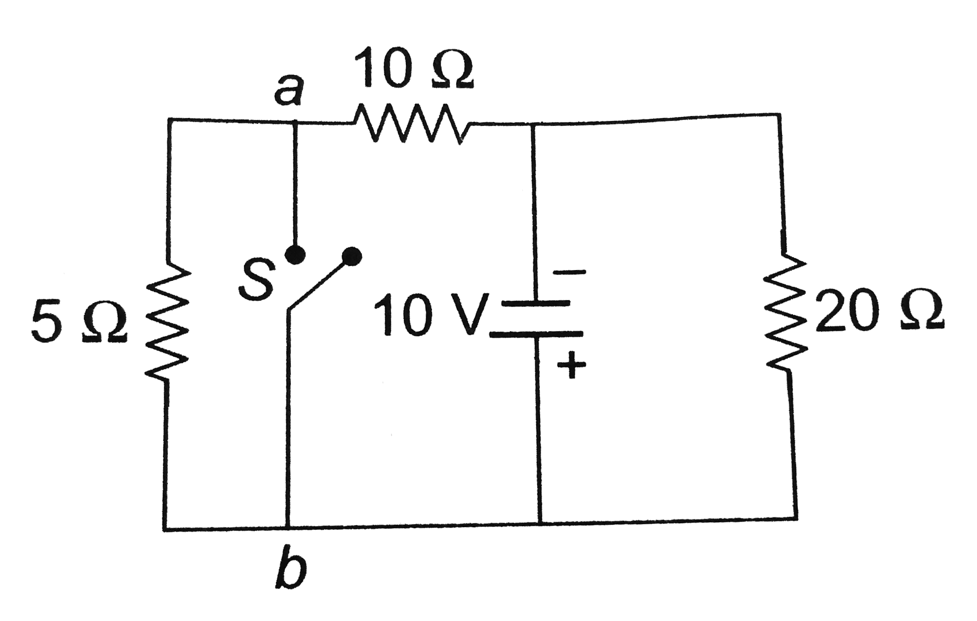
View SolutionIn the circuit shown below, the current that flows from `a` to `b` when switch `S` is closed is
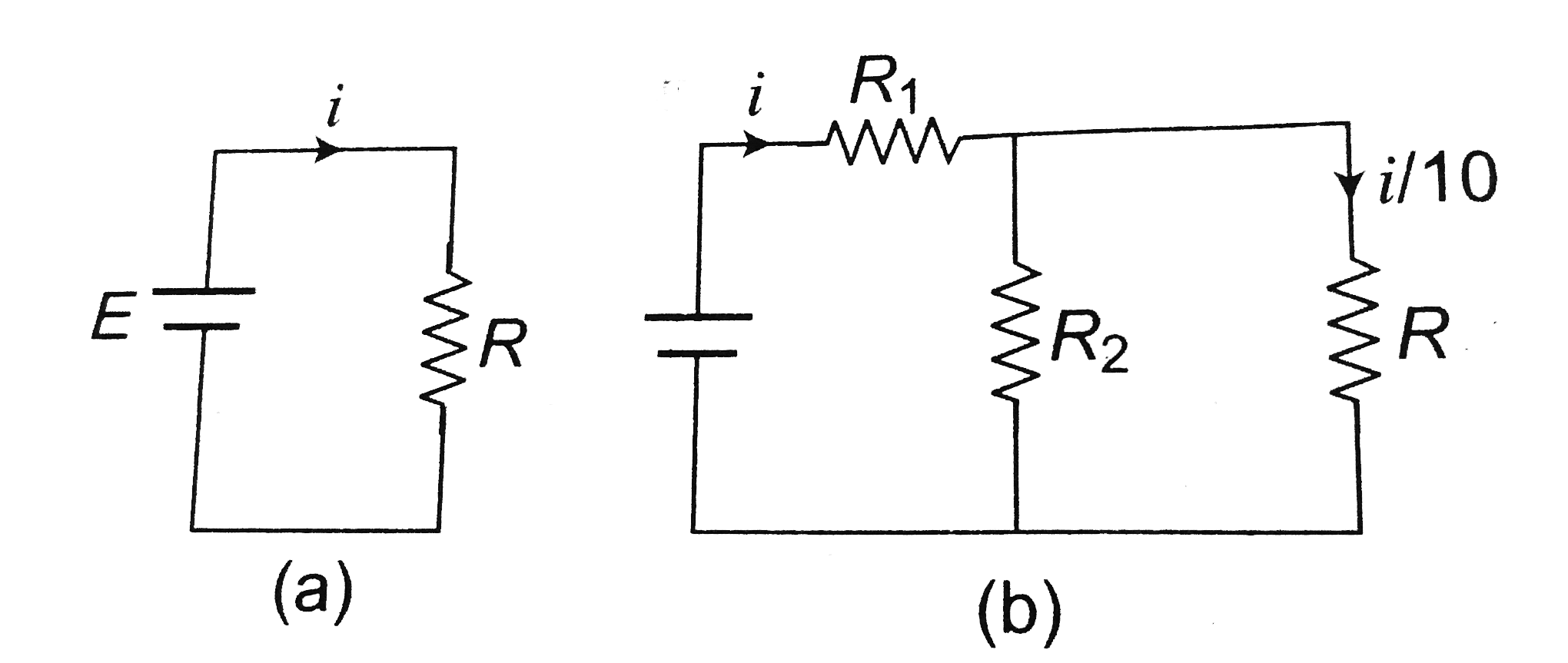
View SolutionConsider the circuit shown in the figure. Both the circuits are taking same current from battery but current through `R` in the second circuit is `(1)/(10) th` of current through `R` in the first circuit. If `R` is `11 Omega`, the value of `R_(1)`
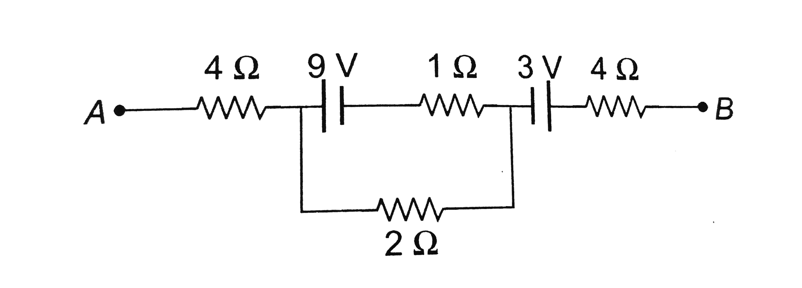
View SolutionIn the circuit shown in figure potential difference between point `A` and `B` is `16 V`. Find the current passing through `2 Omega` resistance.
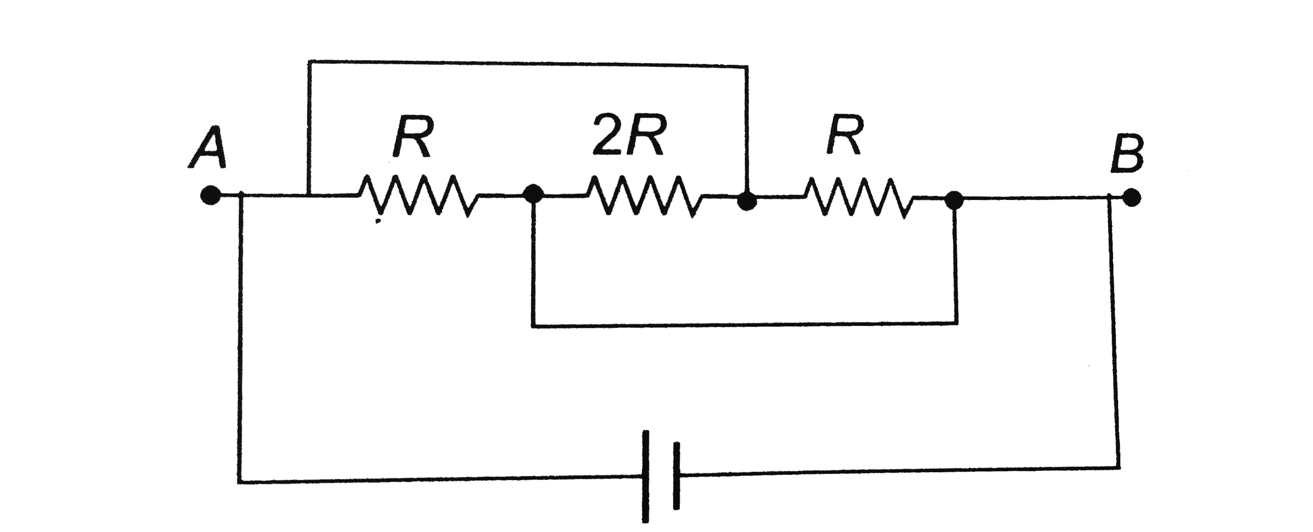
View SolutionA cell of emf `E` has an internal resistance `r` and is connected to rheostat. When resistance `R` of rheostat is changed, correct graph of potentail difference across it is
View SolutionIn the figure shown the current flowing `2 R` is:
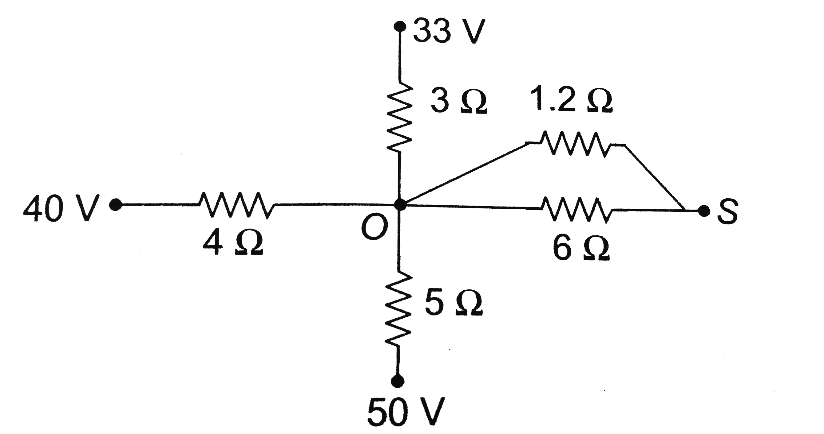
View SolutionIn the given network, the potential at point `O` is (Given `VO = V_(s) = 18 V)`
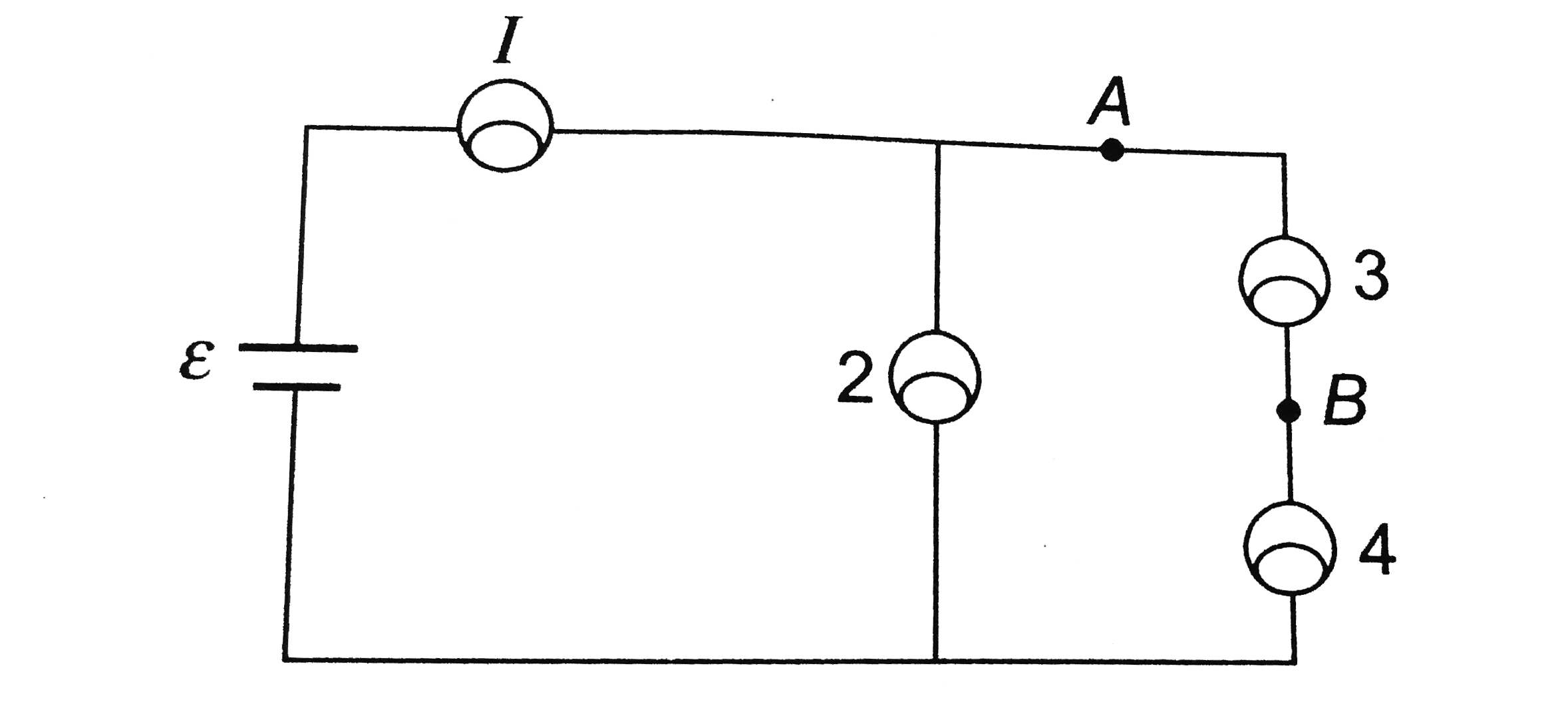
View SolutionFor the circuit shown, a shorting wire of negligible resistance is added to the circuit between points `A` and `B`. When this shorting wire is added, bulb 3 goes out. Which bulb (s) in the circuit brighten ? All bulbs are identical.
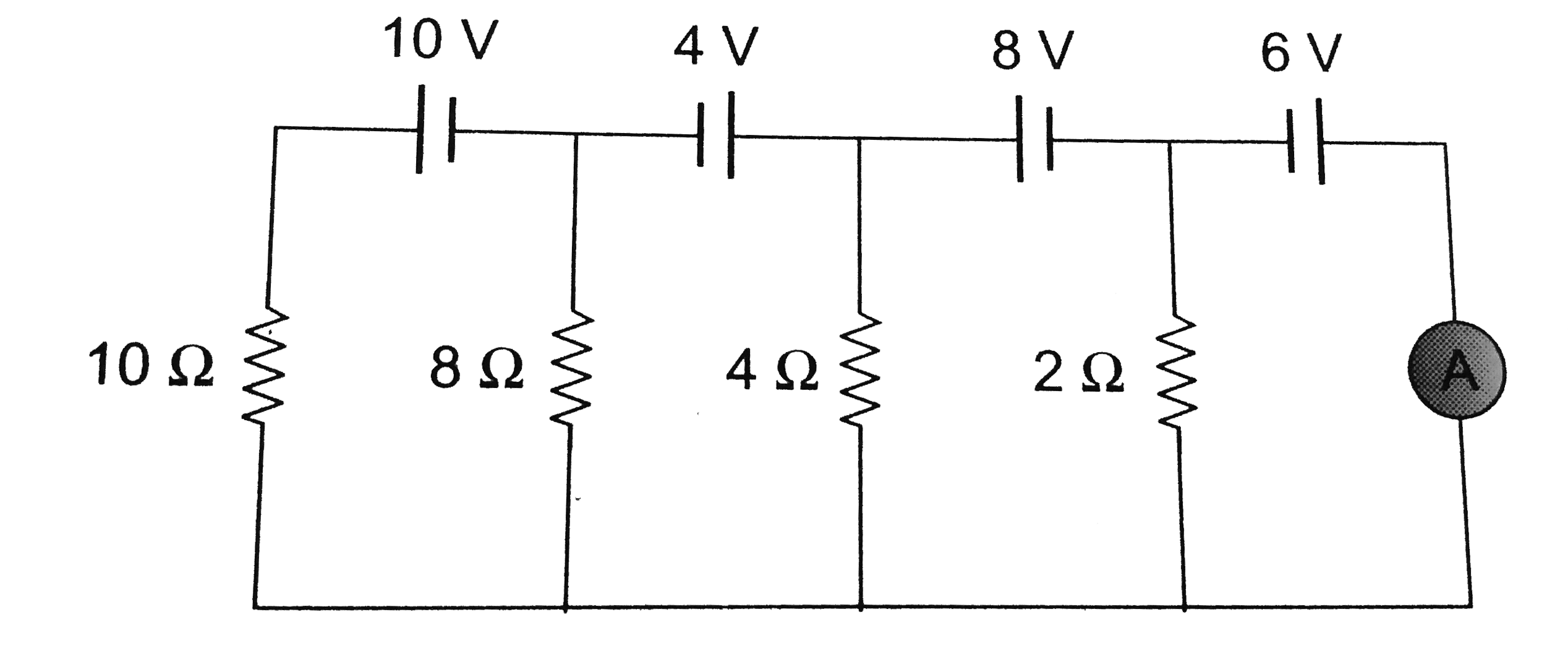
View SolutionFing the reading of the ideal ammeter connected in the given circuit. Assume that the cells have negligible internal resistance.
View SolutionThe circuit is shown in figure. The ratio of current `i_(1) // i_(2)` is
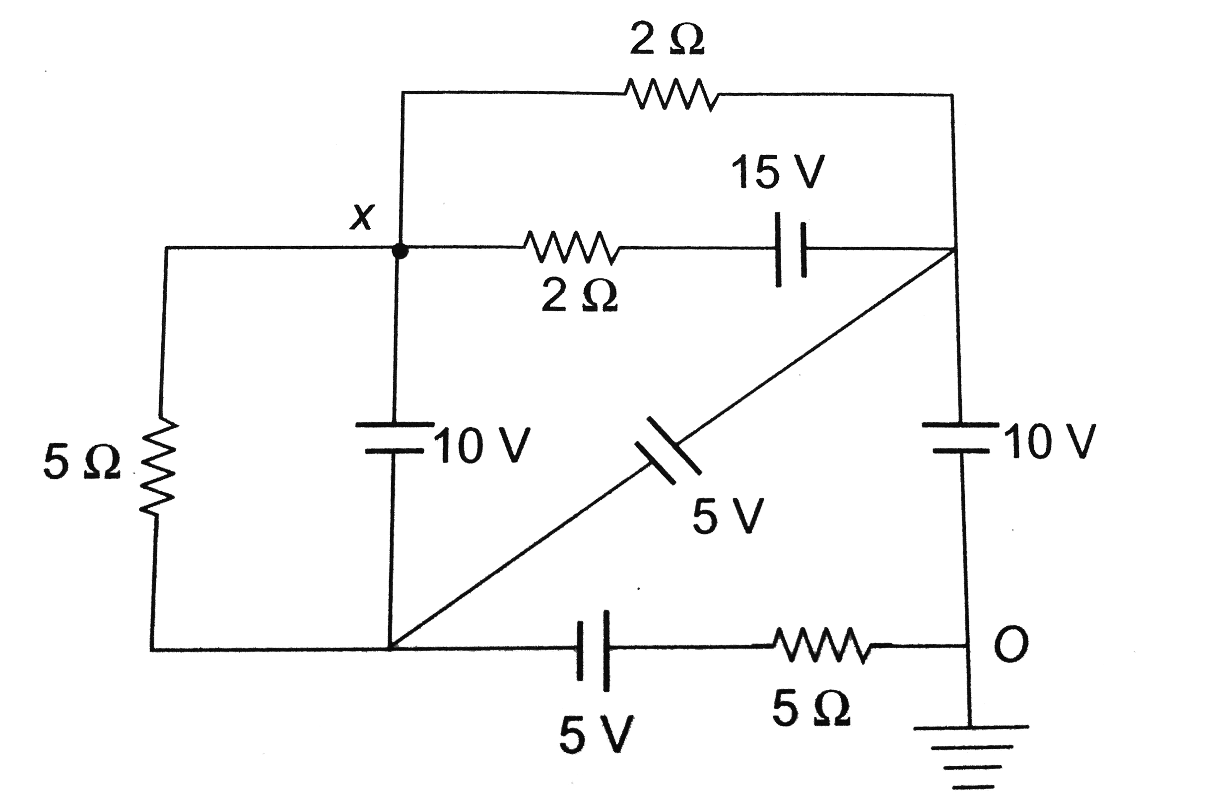
View SolutionIn the circuit shown if point `O` is earthed, the potential of point `X` is equal to
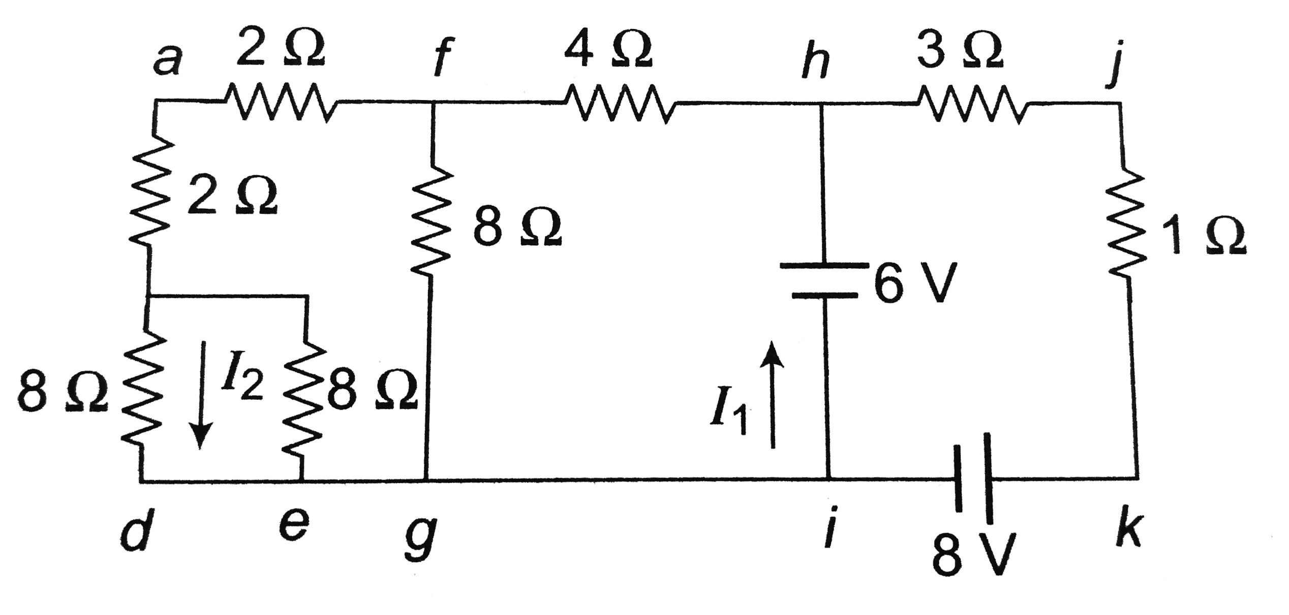
View SolutionIn the circuit shown the currents in `4 Omega` and `8 Omega` resistances are
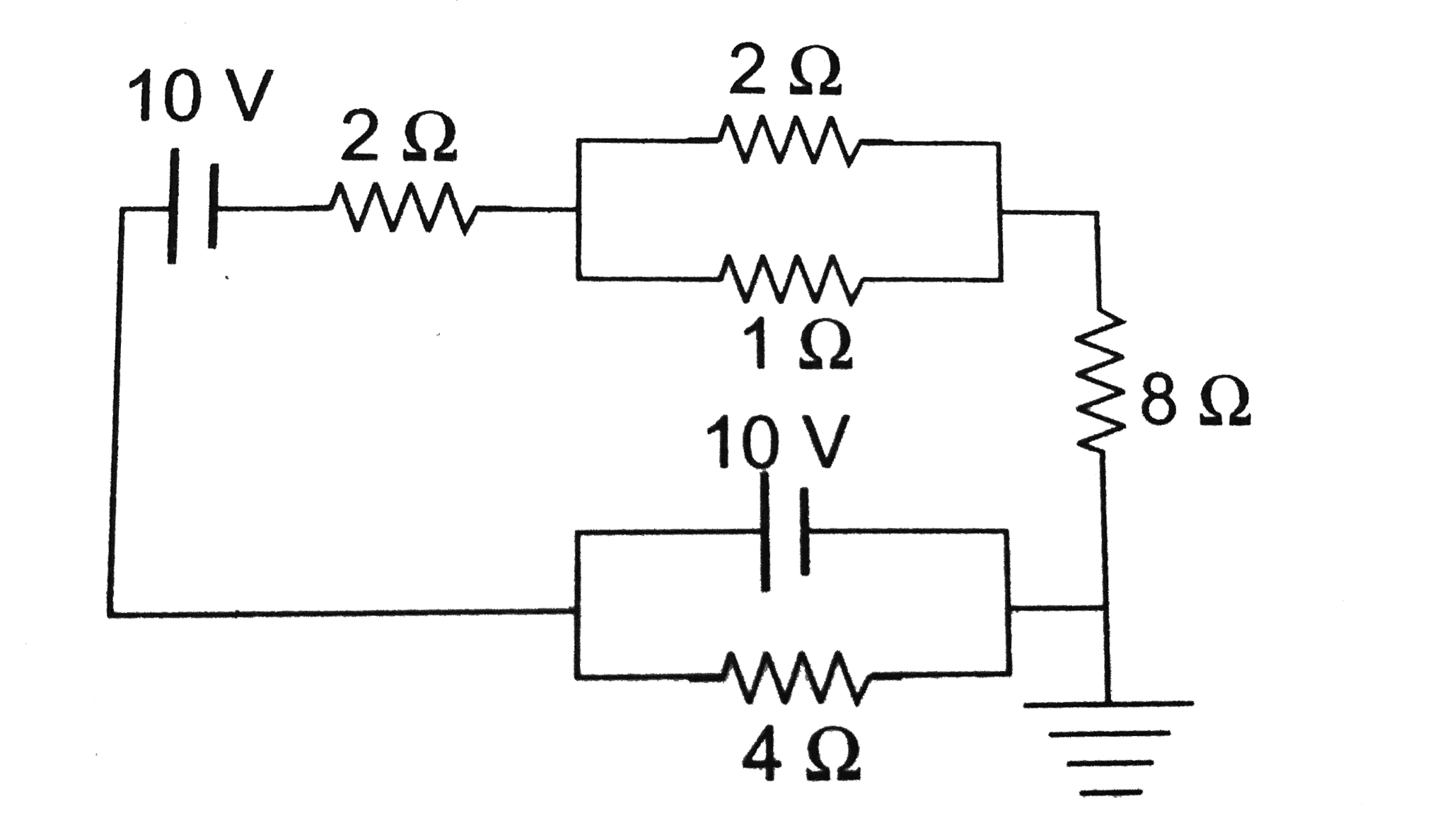
View SolutionAs the switch `S` is closed in the circuit shown in figure, current passed through it is.
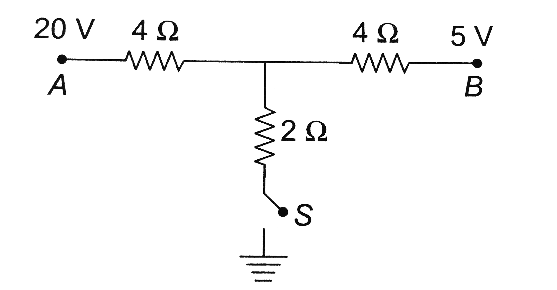
View SolutionFigure showns a network of eight resistors numbered 1 to 8, each equal to `2 Omega`, connected to a `3 V` battery of negligible internal resistance. The current `l` in the circuit is
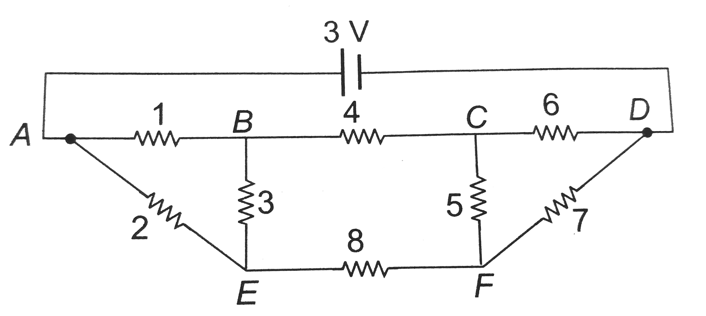
View SolutionThe magnitude in `i` in ampere unit is
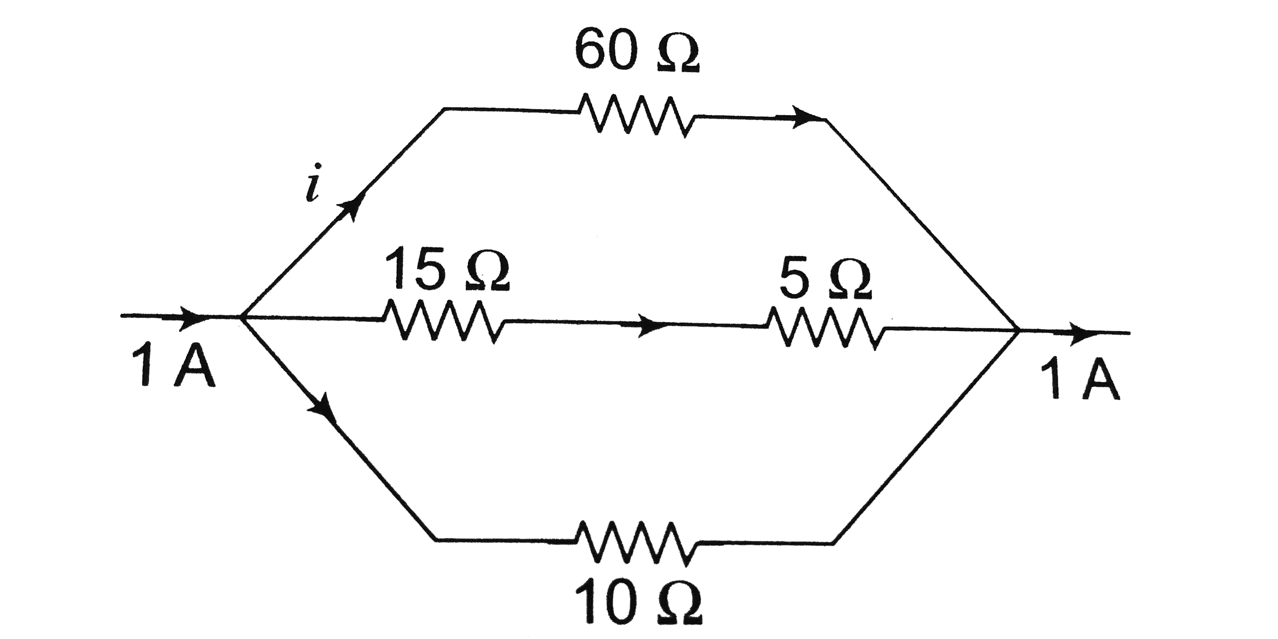
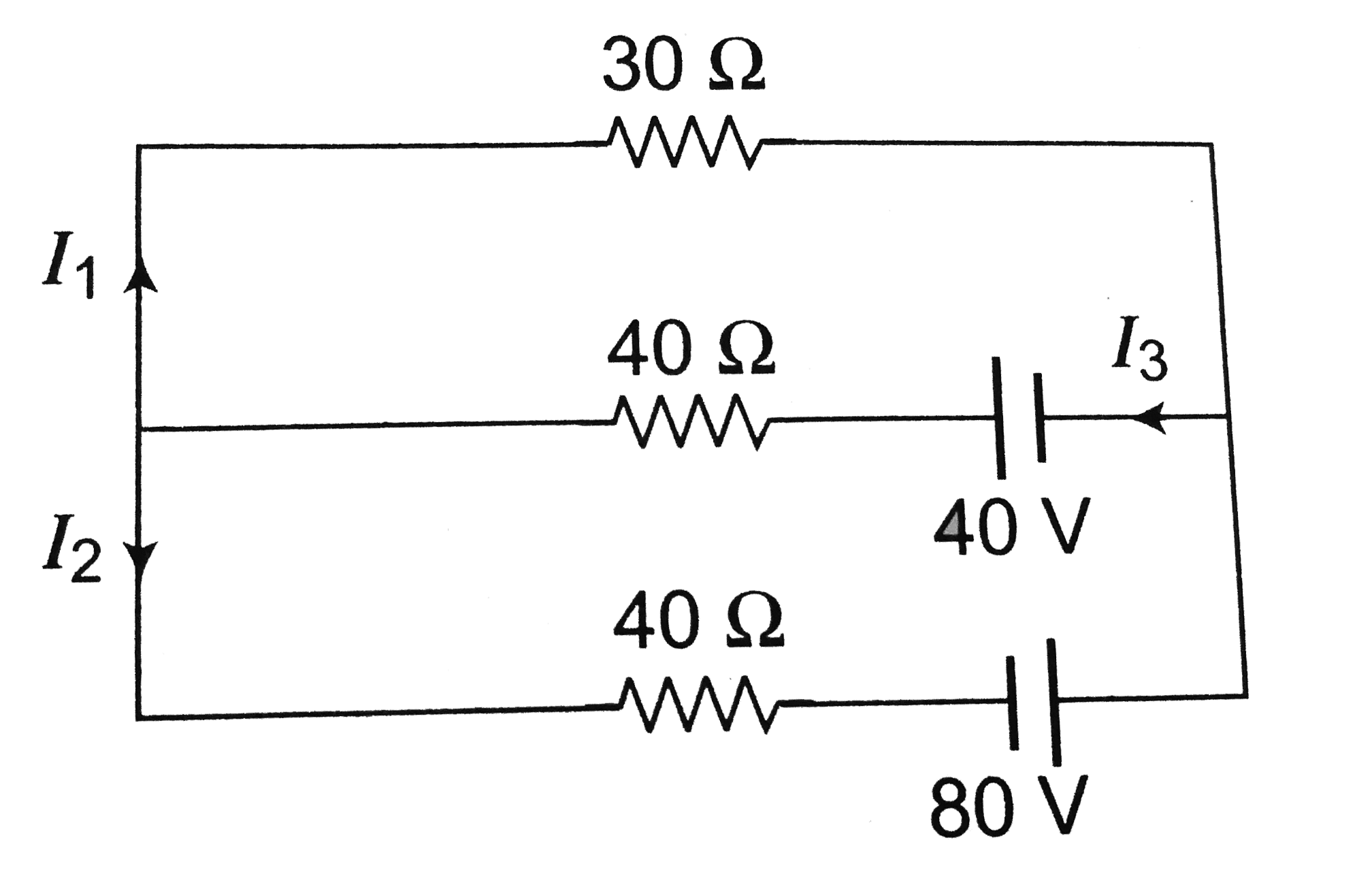
View SolutionIn the given circuit the current `I_(1)` is
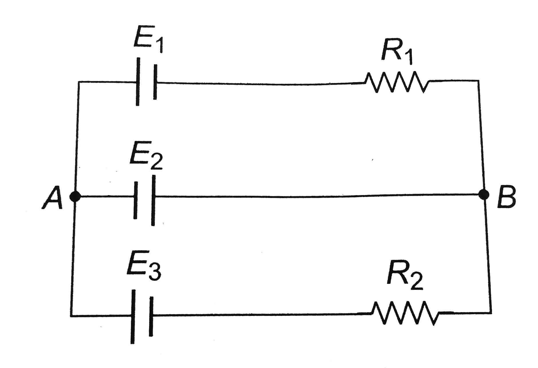
View SolutionIn the circuit shown here, `E_(1) = E_(2) = E_(3) = 2 V` and `R_(1) = R_(2) = 4 ohms`. The current flowing between point `A` and `B` through battery `E_(2)` is
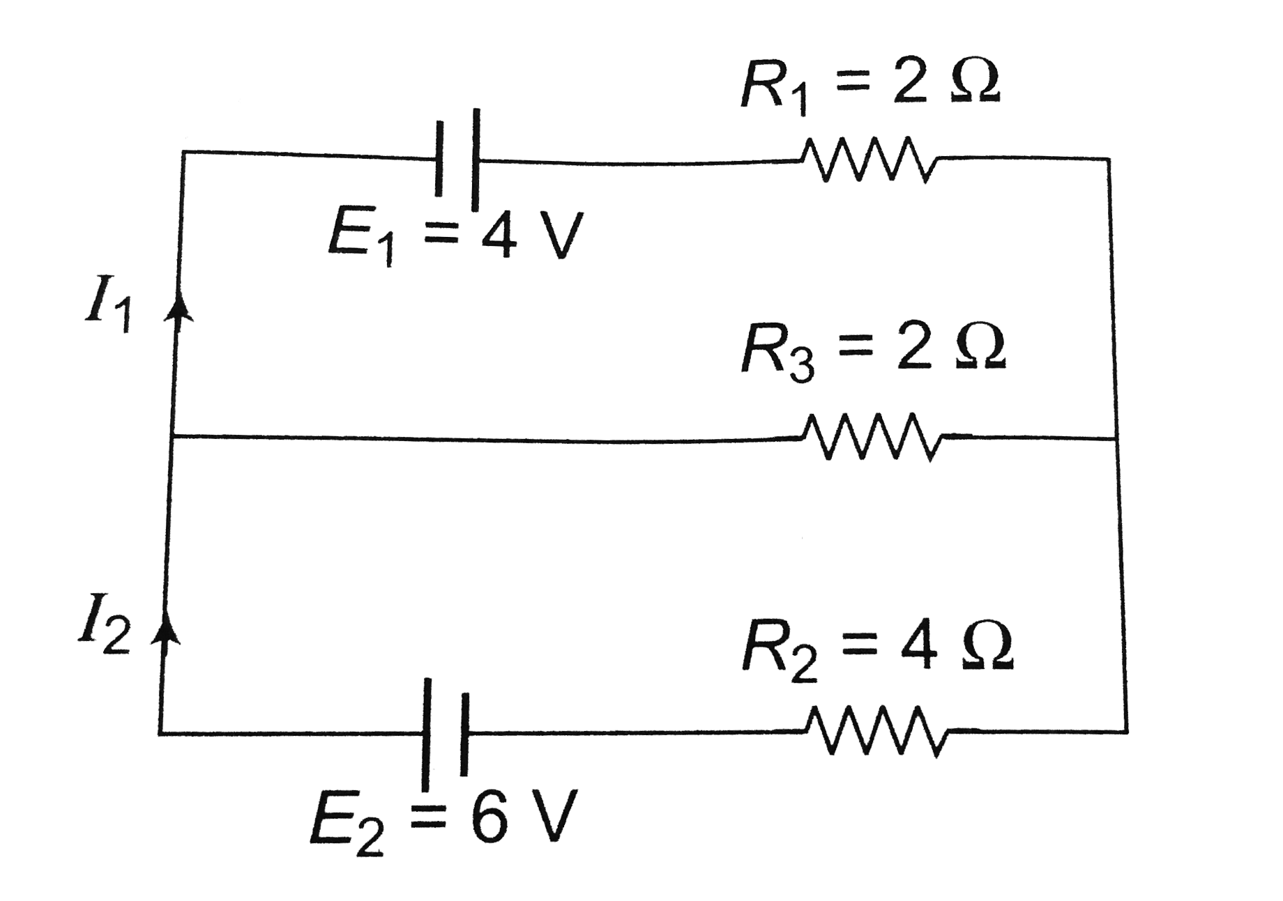
View SolutionIn the circuit shown below `E_(1) = 4.0 V, R_(1) = 2 Omega, E_(2) = 6.0 V, R_(2) = 4 Omega` and `R_(3) = 2 Omega`. The current `I_(1)` is
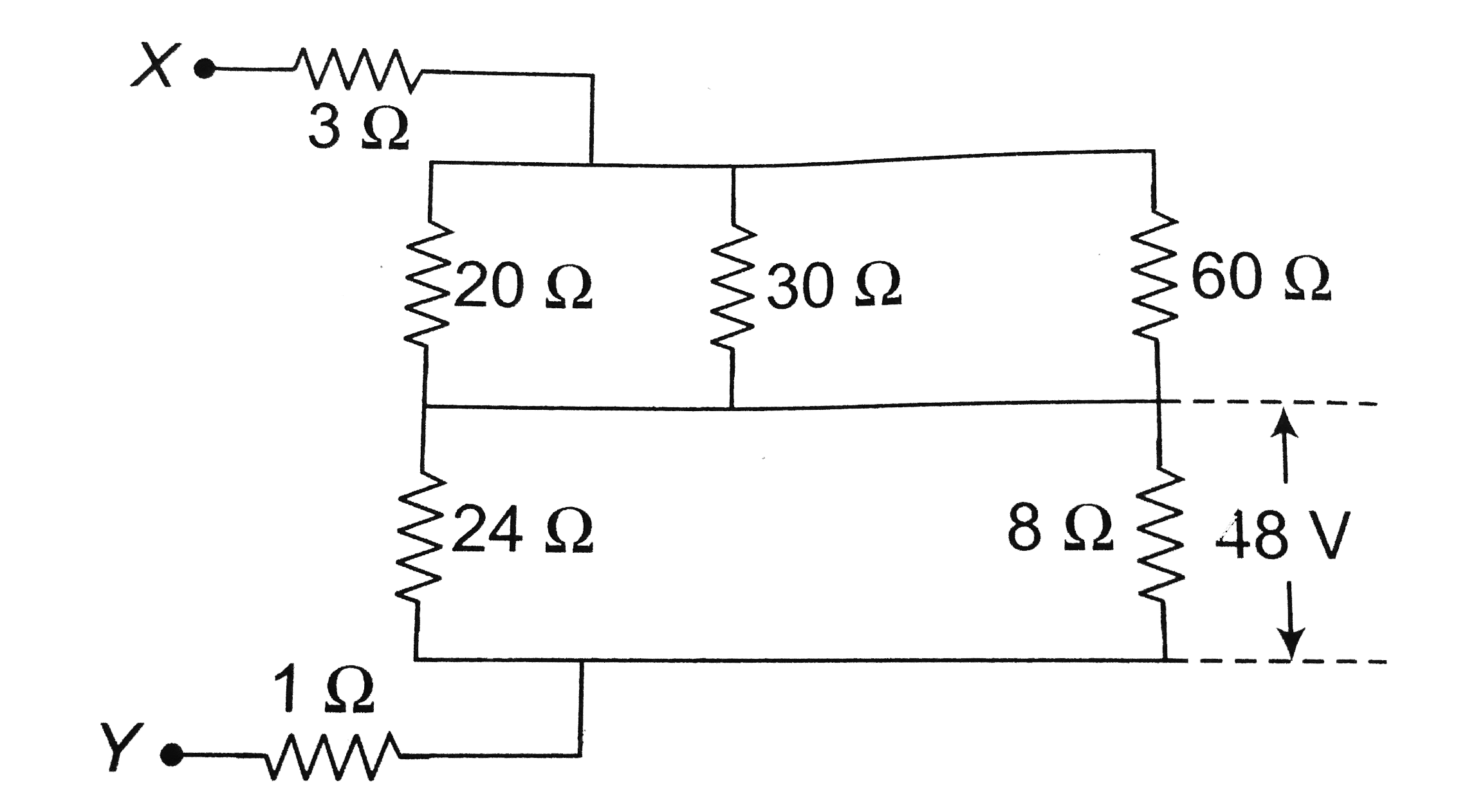
View SolutionThe potential difference across 8 ohm resistance is 48 volt as shownin the figure. The value of potential difference across `X` and `Y` point will be
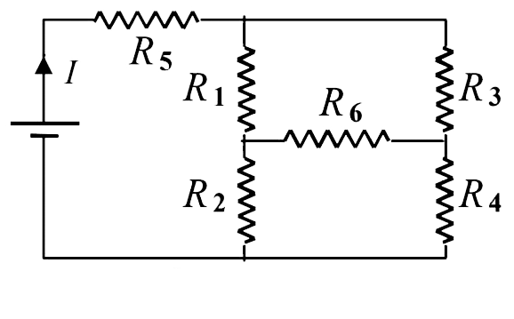
View SolutionIn the given circuit, it is observed that the current I is independent of the value of the resistance `R_6`. Then the resistance values must satisfy
 .
.
View Solution
Kircoff'S Laws And Simple Circuits questions and complete solutions for chapter CURRENT ELECTRICITY of A2Z PHYSICS (HINGLISH) of Class 12
All Exercises from A2Z Class 12 PHYSICS CURRENT ELECTRICITY
- AIIMS Questions
- AIPMTNEET Questions
- Ammeter And Voltmeter
- Assertion- Reason
- Combination And Resistivity
- Heating Effect Of Current
- Kircoff'S Laws And Simple Circuits
- Potentiometer And Meter Bridge
- Problems Based On Mixed Concepts
- R-C Circuits
- Resistivity And Drift Velocity
- Section - A
- Section - C
- Section B - Assertion Reasoning
- Section D - Chapter End Test