Complete Solutions to Ammeter And Voltmeter of chapter CURRENT ELECTRICITY of Class 12 book with complete answers and questions
| Class 12 | PHYSICS |
| Chapter | CURRENT ELECTRICITY |
| A2Z | Ammeter And Voltmeter |
| Number Of Questions | 41 |
| Academic Year | 2023-24 |
A galvanometer can be converted into an ammeter by connecting
01:50View SolutionThe net resistance of a voltmeter should be large to ensure that
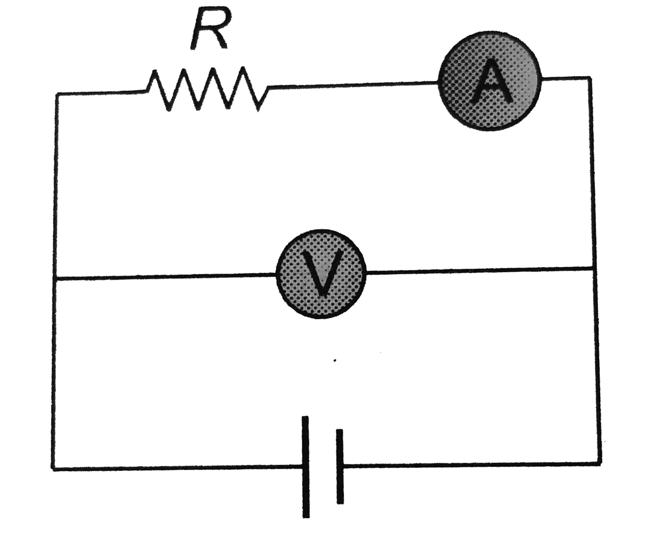
01:59View SolutionAn ammeter and a voltmeter of resistance `R` connected in seires to an electric cell of negligible internal resistance. Their readings are `A` and `V` respecitvely. If another resistance `R` is connected in parallel with the voltmeter
02:18View SolutionA cell of itnernal resitance `1.5 Omega` and of e.m.f. `1.5` volt balances `500 cm` on a potentiomter wire. If a wirr of 15 `Omega` is connected between the balance point and the cell, then tha balance point will shift
01:24View SolutionA voltmeter of resistance `1000 Omega` gives full scale deflection when a current of `100 mA` flow through it. The shunt resistance required across it to enable it to be used as an ammeter reading `1 A` at full scale deflection is
02:53View SolutionA voltmeter has resistance of 2000 ohms and it can measure upto `2 V`. If we want ot increase its range to `10 V` then the, required resistance in series will be
01:21View SolutionA galvanometer has a resistance of `25 ohm` and a maximum of `0.01 A` current can be passed through it. In order to change it into an ammeter of range `10 A`, the shunt resistance required is
02:16View SolutionAn ammeter gives full deflection when a current of `2 amp`. Flows through it. The resistance of ammeter is `12 ohms`. If the same ammeter is to be used for measuring a maximum current of `5 amp`, then the ammeter must be connected with a resistance of
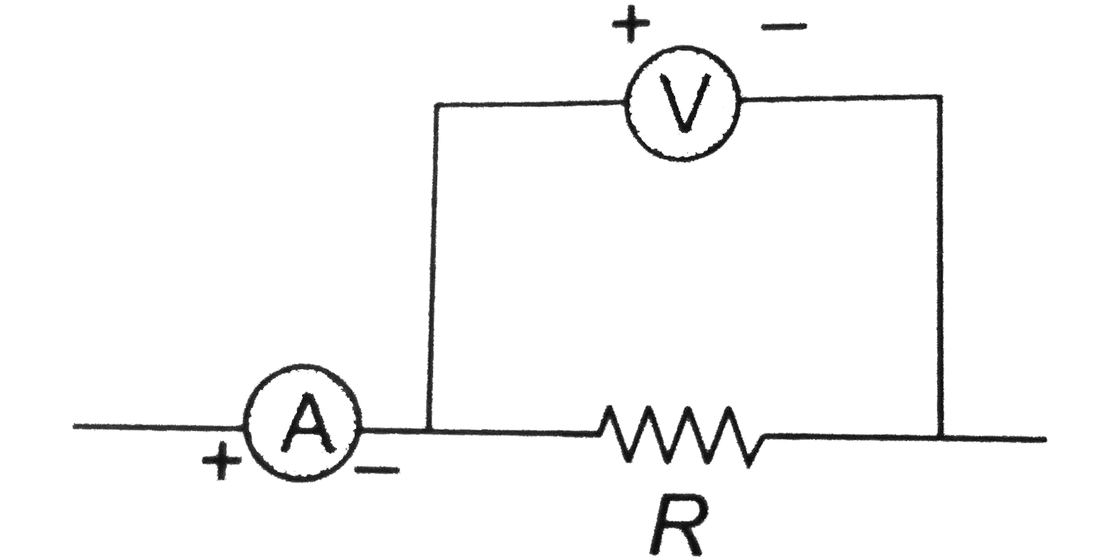
02:25View SolutionIn the given circuit, the ratio of voltmeter reading to the ammeter reading is `R'`. If resistance of ammeter is `RA` and that of voltmeter `RV`, then
 02:02View Solution
A moving coil galvanometer has 150 equal divisions. Its current sensitivity is 10-divisions per milliampere and voltage sensitivity is 2 divisions per millivolt. In order that each division reads 1 volt, the resistance in ohms needed to be connected in series with the coil will be -
05:46View SolutionA galvanometer has 30 divisions and a sensitivity `16 mu A //"div"`. It can be converted into a voltmeter to read `3 V` by connecting
03:00View SolutionA galvanometer whose resistance is `120 Omega` gives full scale deflection with a curretn of `0.5 A` so that it can read a maximum current of `10 A`. A shunt resistance is added in parallel with it. The resistance of the ammeter so formed is
03:14View SolutionWe have a galvanometer of resistance `25 Omega`. It is shunted by a `2.5 Omega` wire. The part of total current that flows through the galvanometer is given as
02:26View SolutionA voltmeter having a resistance of 998 ohms is connected to a cell of e.m.f. 2 volt and internal resistance 2 ohm. The error in the measurment of e.m.f. will be
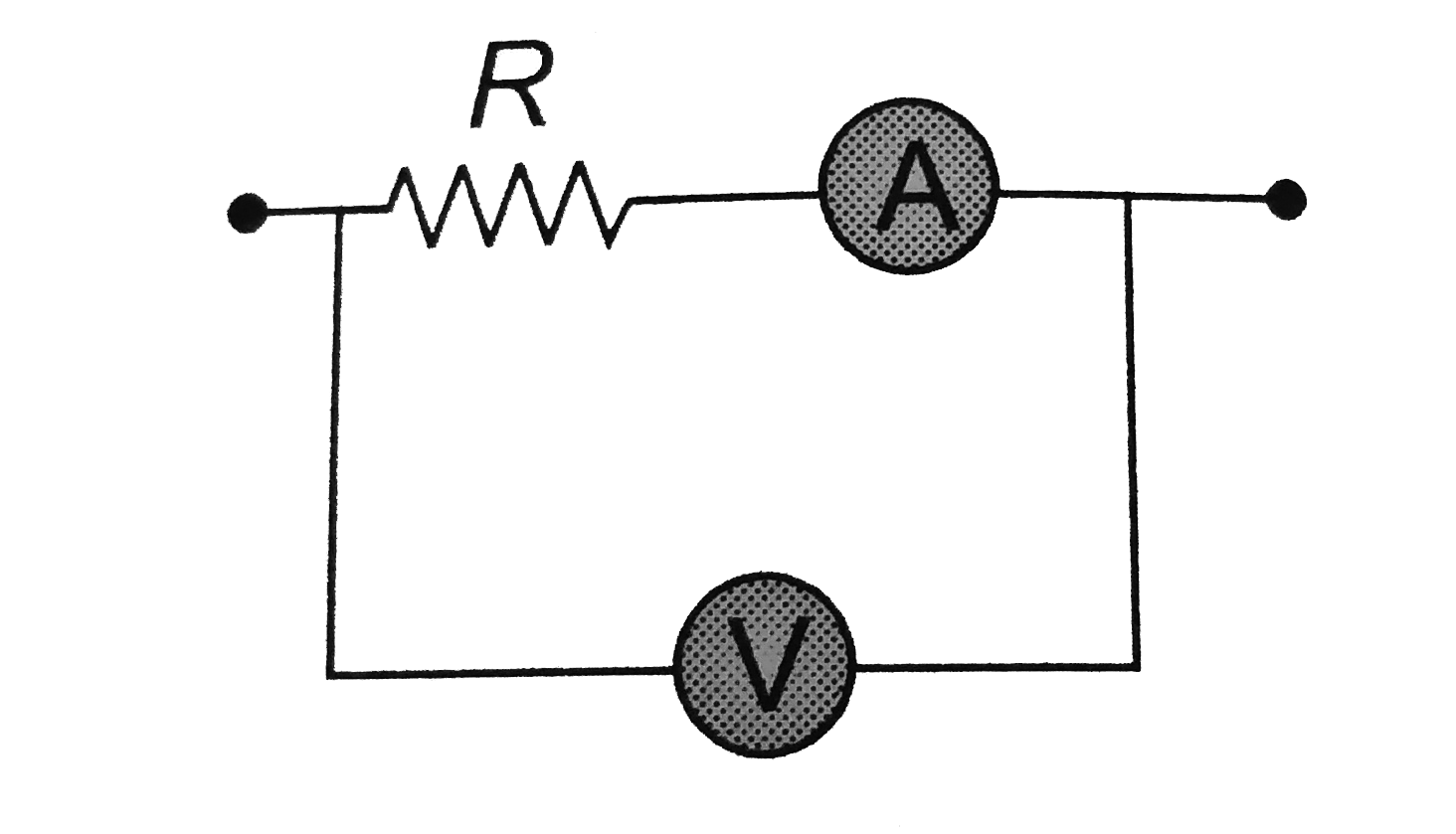
03:53View SolutionA cardidate connects a moving coil voltmeter `V`, a moving coil ammeter `A` and a resistance `R` as shown in figure. If the voltmeter reads `24 V` and the ammeter reads `4 A`, R is
 02:29View Solution
`50 Omega` and `100 Omega` resistors are connected in series. This connection is connected with a battery of 2.4 volts. Whne a voltmeter, then the reading of the voltmeter will be `100 Omega` resistor, then eh reading of the voltmeter will be
03:18View SolutionA galvanometer coil has a resistance `90 Omega` and full scale deflection current `10 mA`. A `910 Omega` resistance is connected in series with the galvanometer to make a voltmeter. If the least count of the voltmeter is `0.1 V` the number of divisions on its scale is
02:53View SolutionIn the circuit shown the resistance of voltmeter is `10000 ohm` and that of ammeter is `20 ohm`. The ammeter reading is `0.10 amp` and voltmeter reading is 12 volts. Then `R` is equal to
 01:57View Solution
A `100 V` voltmeter of internal resistance `20 k Omega` in series with a high resistance `R` is connected to a `110 V` line. The voltmeter reads `5 V`, the value of `R` is
03:13View SolutionA voltmeter with resistance `500 Omega` is used to measure the emf of a cell of internal resistance `4 Omega`. The percentage error in the reading of the voltmeter will be
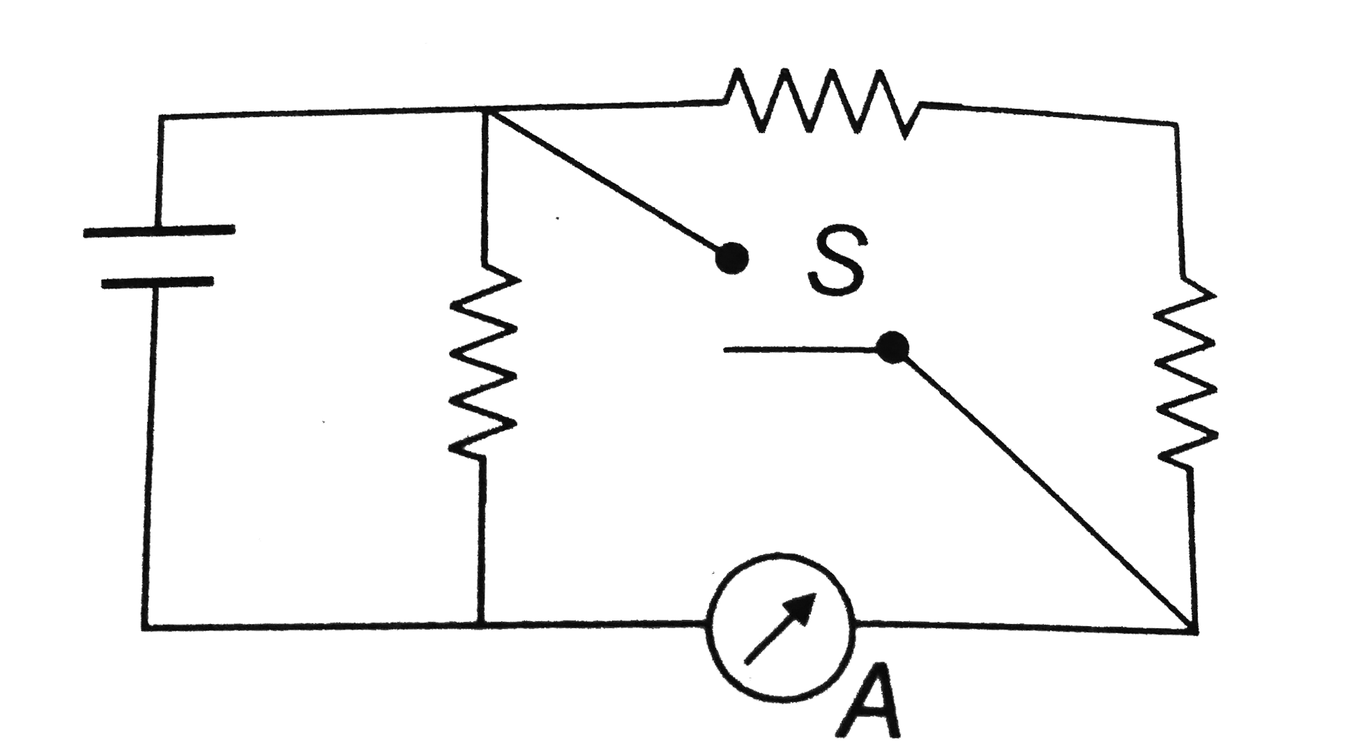
04:26View SolutionIn the circuit shown, the reading of the Ammter is doulbed after the switch is closed. Each resistor has a resistance `= 1 Omega` and the ideal cell has an e.m.f. `= 10 V`. Then the ammeter has a resistance equal to
 04:41View Solution
In the adjoining circuit, the e.m.f. of the cell is 2 volt and the internal resistance is negligible. The resistance of the voltmeter is `80 ohm`. The reading of the voltmeter will be
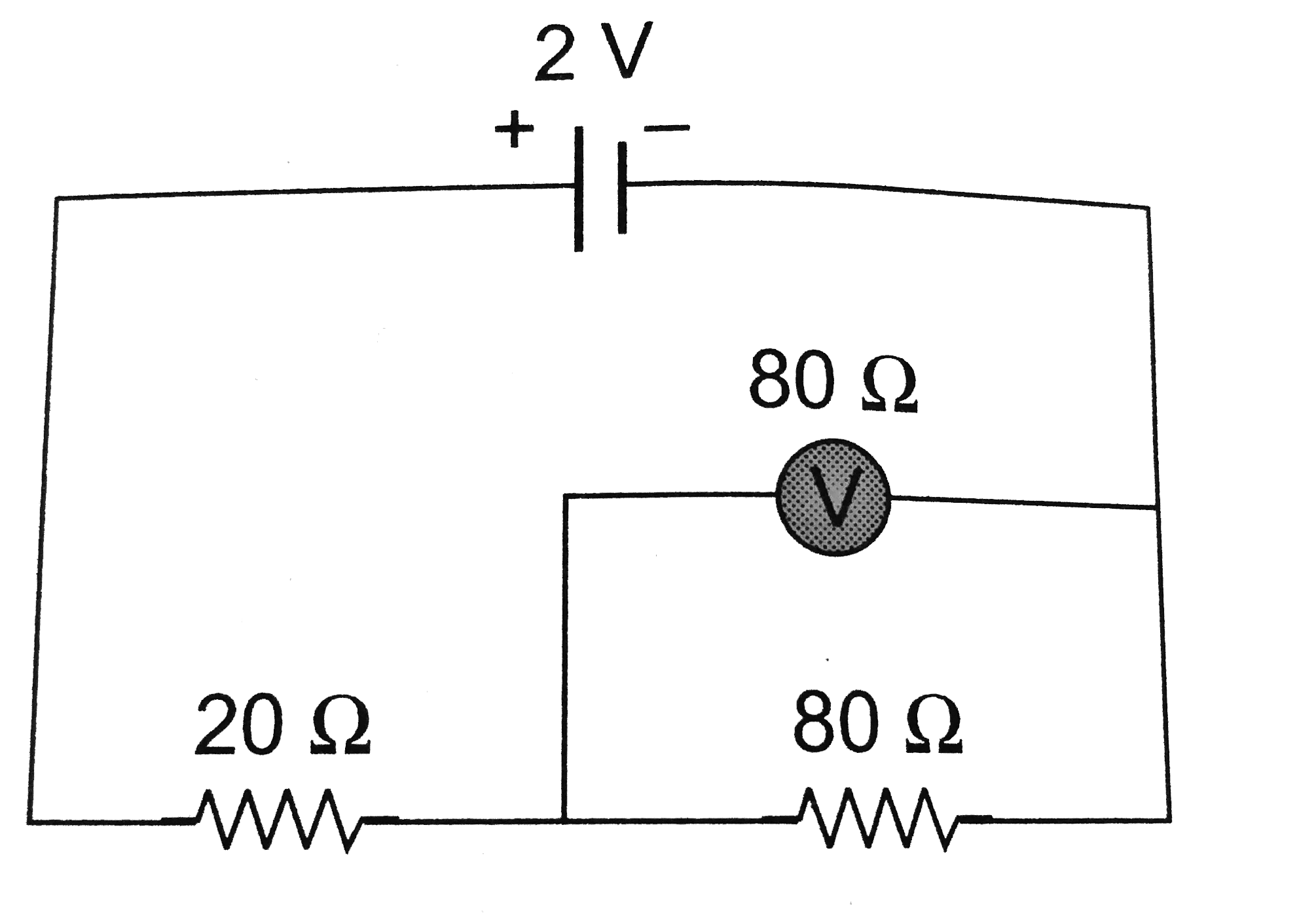 03:24View Solution
It is required to measure equivalent ressitance of circuit with ideal battery, ideal voltmeter and ideal ammeter. Which circuit diagram shows voltmeter `V` and ammter. A correctly position to measure the total resistance of circuit ?
02:07View SolutionIn the circuit shown the reading of ammeter and voltmeter are `4 A` and `20 V` respectively. The meters are non ideal, then `R` ia
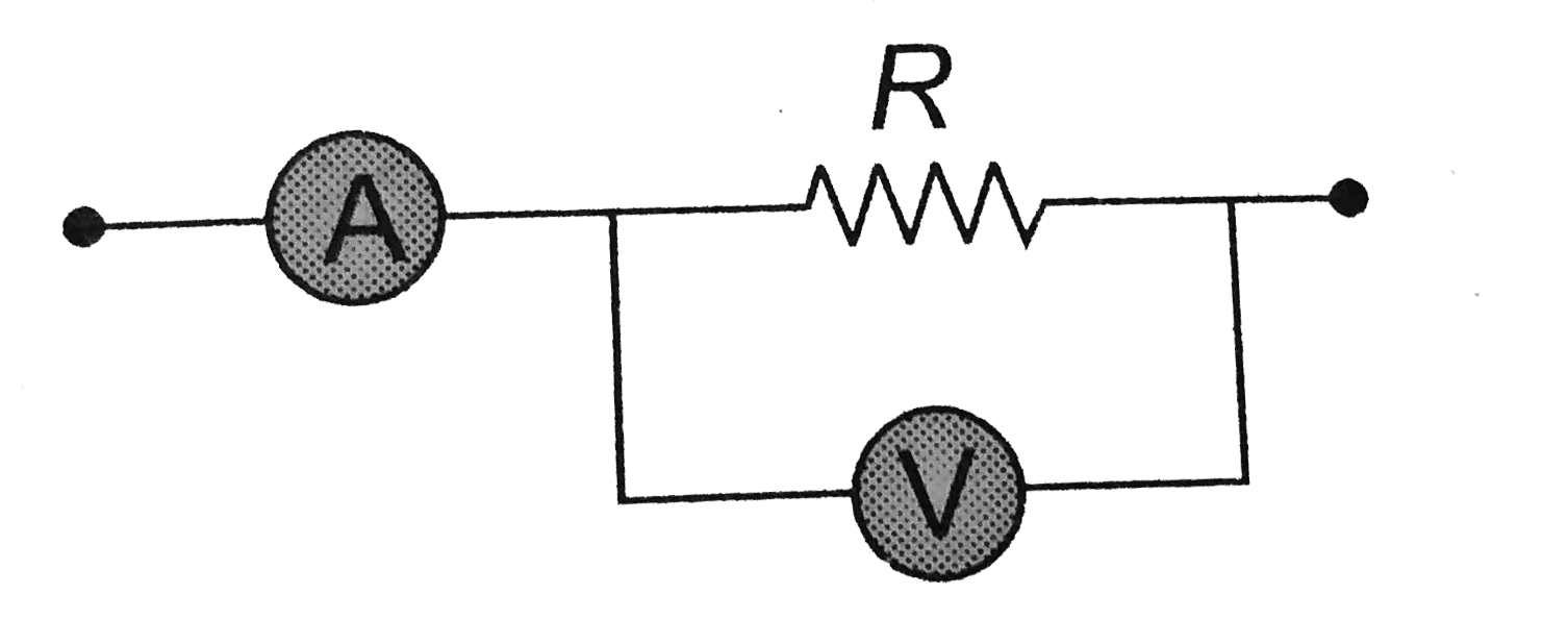 02:06View Solution
Voltmeters `V_(1)` and `V_(2)` are connected in series across a `D.C.` line `V_(1)` reads 80 volts and has a per volt resistance of `200 ohms`, `V_(2)` has a total resistance of 32 kilo ohms.
The line voltage is04:35View SolutionTwo resistance of `400 Omega` and `800 Omega` are connected in series with 6 volt battery of negligible internal resistance. A voltmeter of resistance `10,000 Omega` is used to measure the potential difference across `400 Omega`. The error in measurement of potential difference in volts approximatley is
04:49View SolutionA galvanometer, having a resistance of `50 Omega` gives a full scale deflection for a current of `0.05 A`. The length in meter of a resistance wire of area of cross-section `2.97 xx 10^(-2) cm^(2)` that can be used to convert the galvanometer into an ammeter which can read a maximum of `5 A` current is (Specific resistance of the wire `5 xx 10^(-7) omega m`)
03:31View SolutionWhat is the reading of voltmeter in the following figure ?
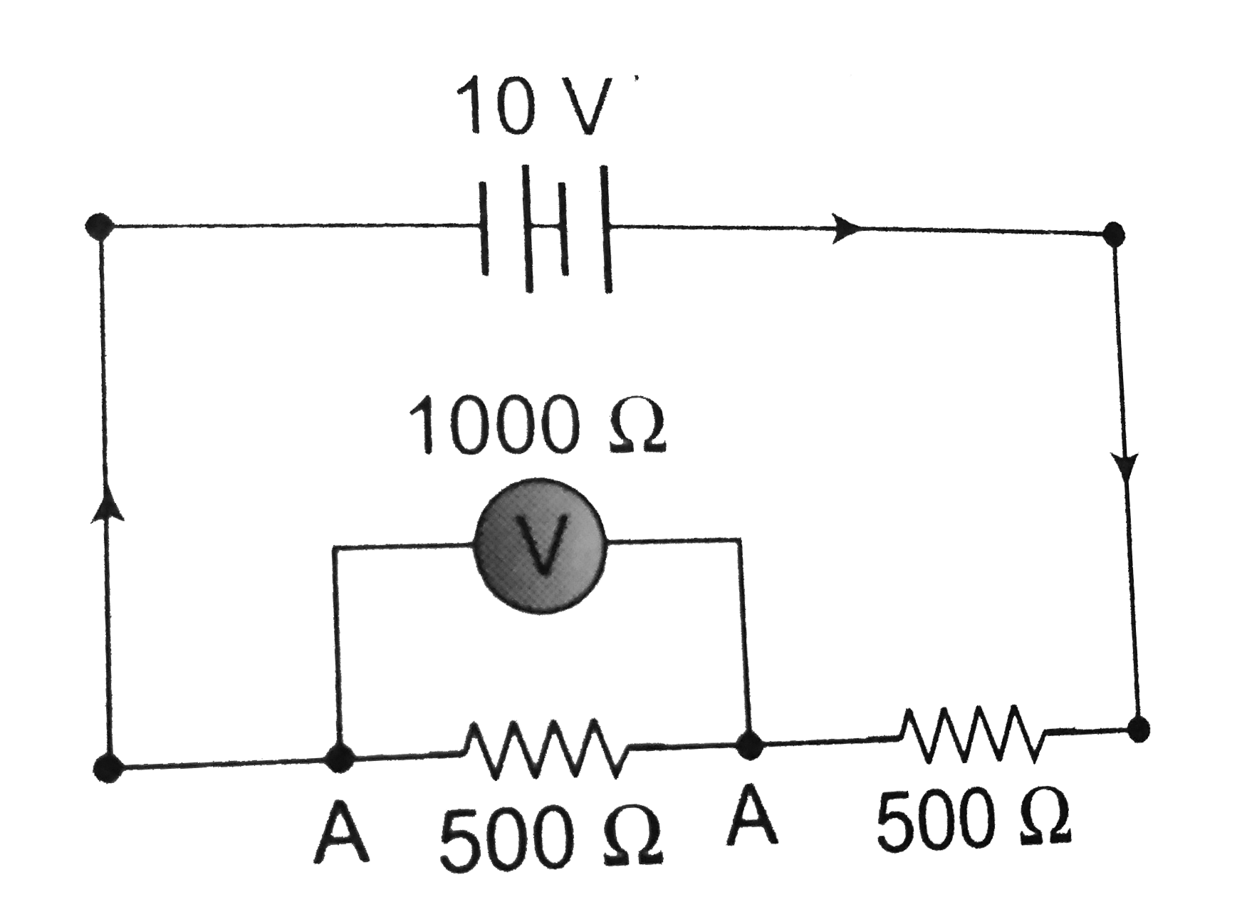 02:36View Solution
In the given circuit, the galvanmeter `G` will show zero deflection if
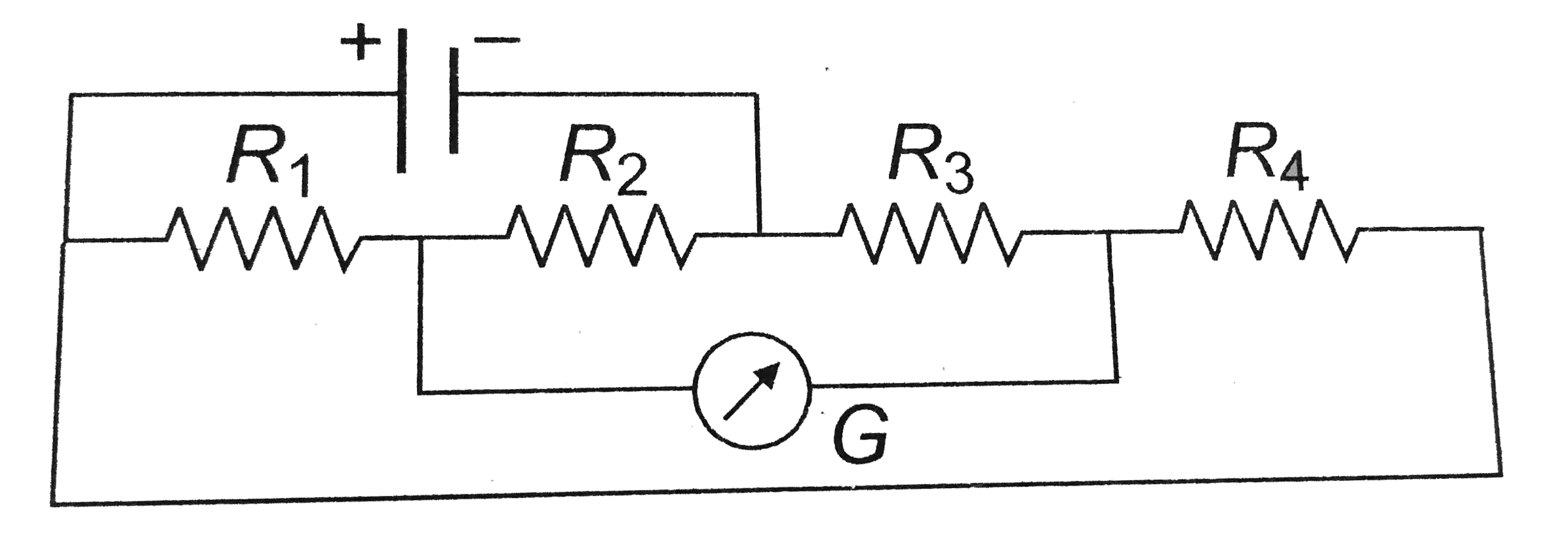 03:07View Solution
A moving coil galvanometer has 150 equal divisions. Its current sensitivity is 10 division per milliampere and voltage sensitivity is 2 divisions per millivolt. In order that each division reads 1 volt, the resistance in ohms needed to be connected in series with the coil will be
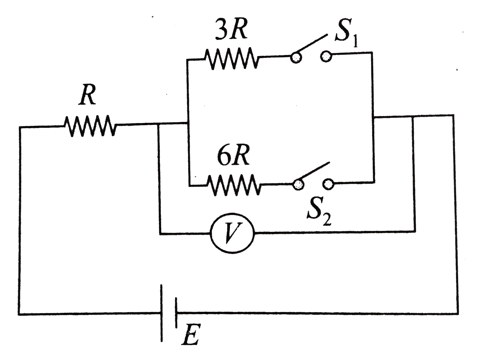
04:26View SolutionIn the circuit shown in figure, reading of voltmeter is `V_1` when only `S_1` is closed, reading of voltmeter is `V_2` when only `S_2` is closed, and reading of voltmeter is `V_3` when both `S_1 and S_2` are closed. Then .
 03:21View Solution
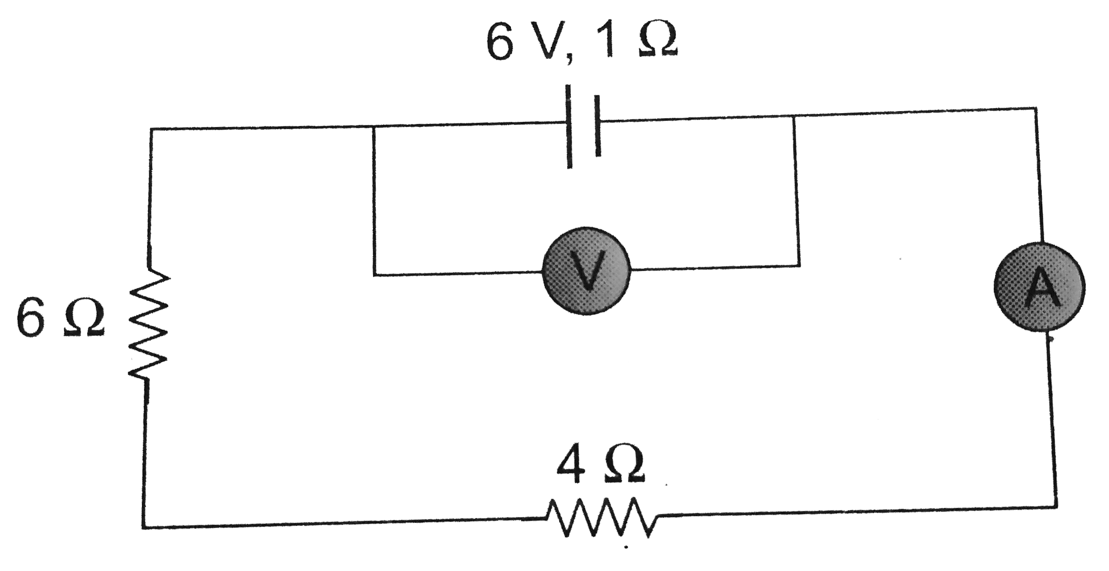
In the circuit shown here, the readings of the ammeter and voltmeter are
 02:53View Solution
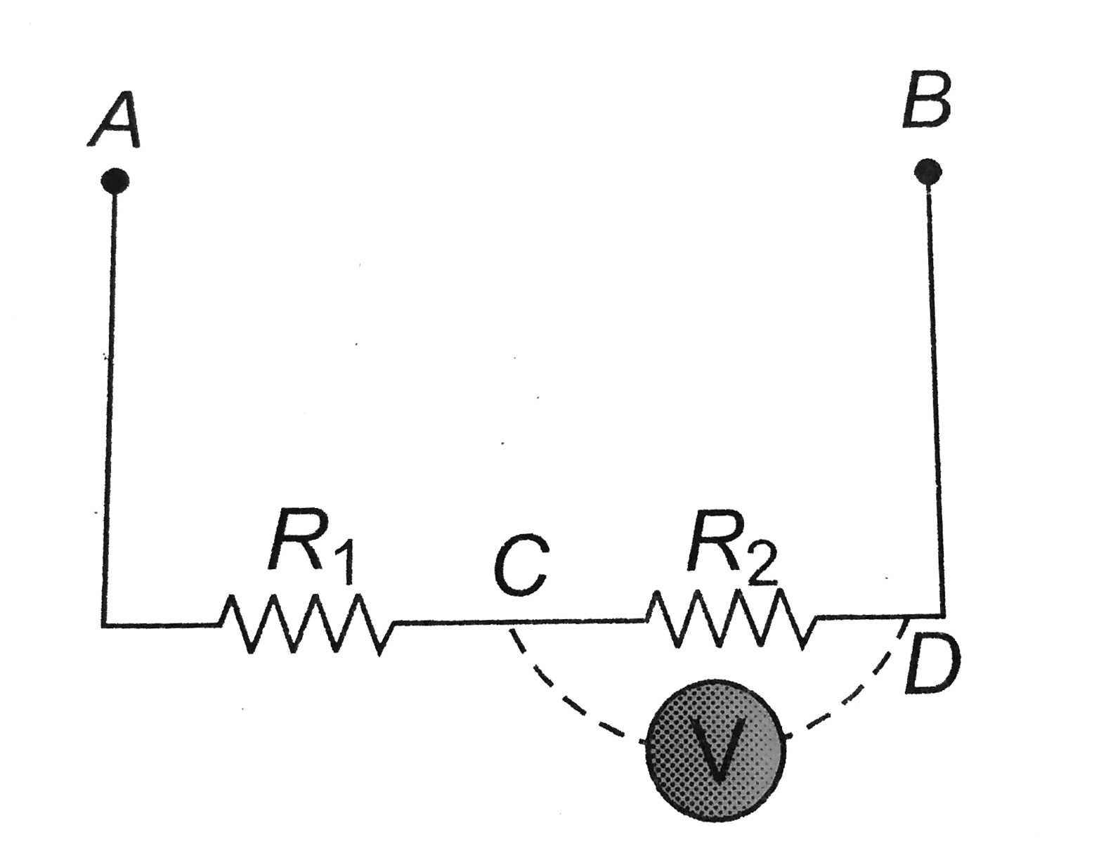
Resistances `R_(1)` and `R_(2)` each 60 are connected in series as shown in figure. The potential difference between `A` and `B` is kept 120 volt. Then what will be tha reading of voltmeter connected between thapoint `C` and `D` if resistance of voltmeter is `120 Omega` ?
 02:16View Solution
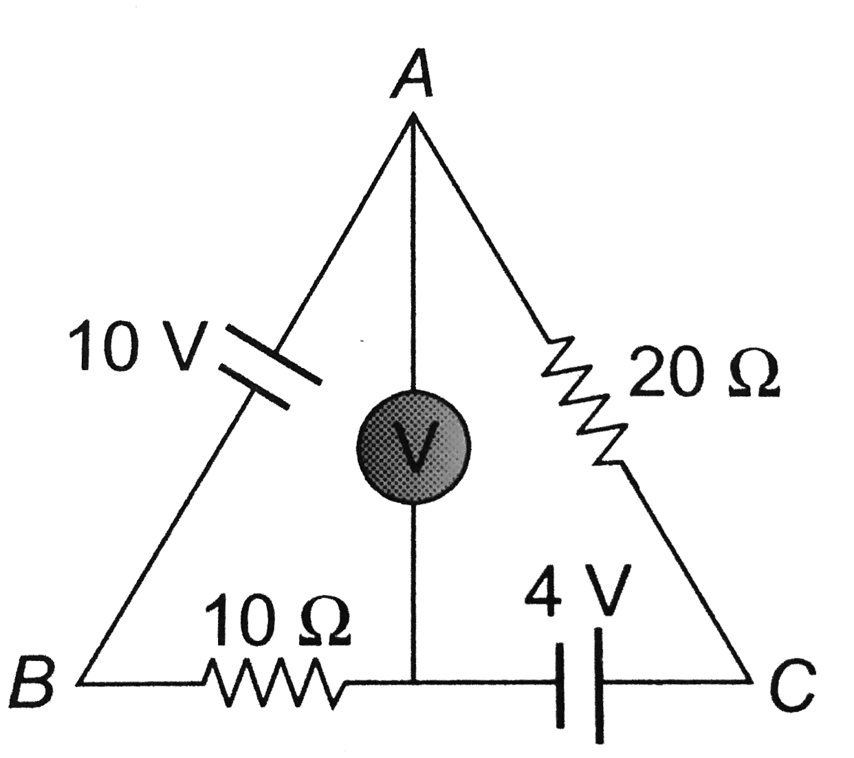
The reading of the ideal voltmeter in the adjoining diagram will be
 03:11View Solution
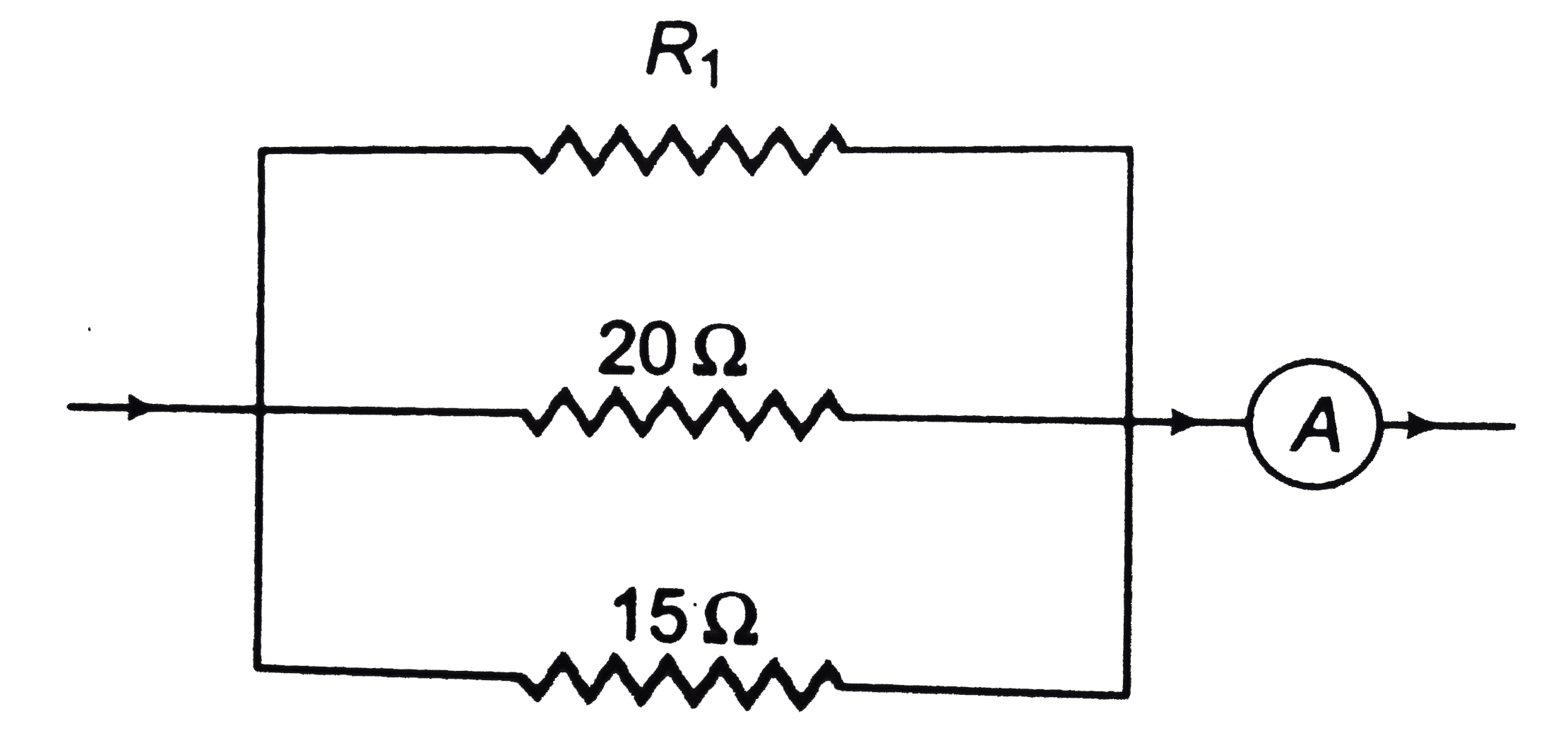
In the given circuit current flowing through the resistance `20Omega` is `0.3A,` while the ammeter reads 0.8 A. What is the value of `R_1`
 03:24View Solution
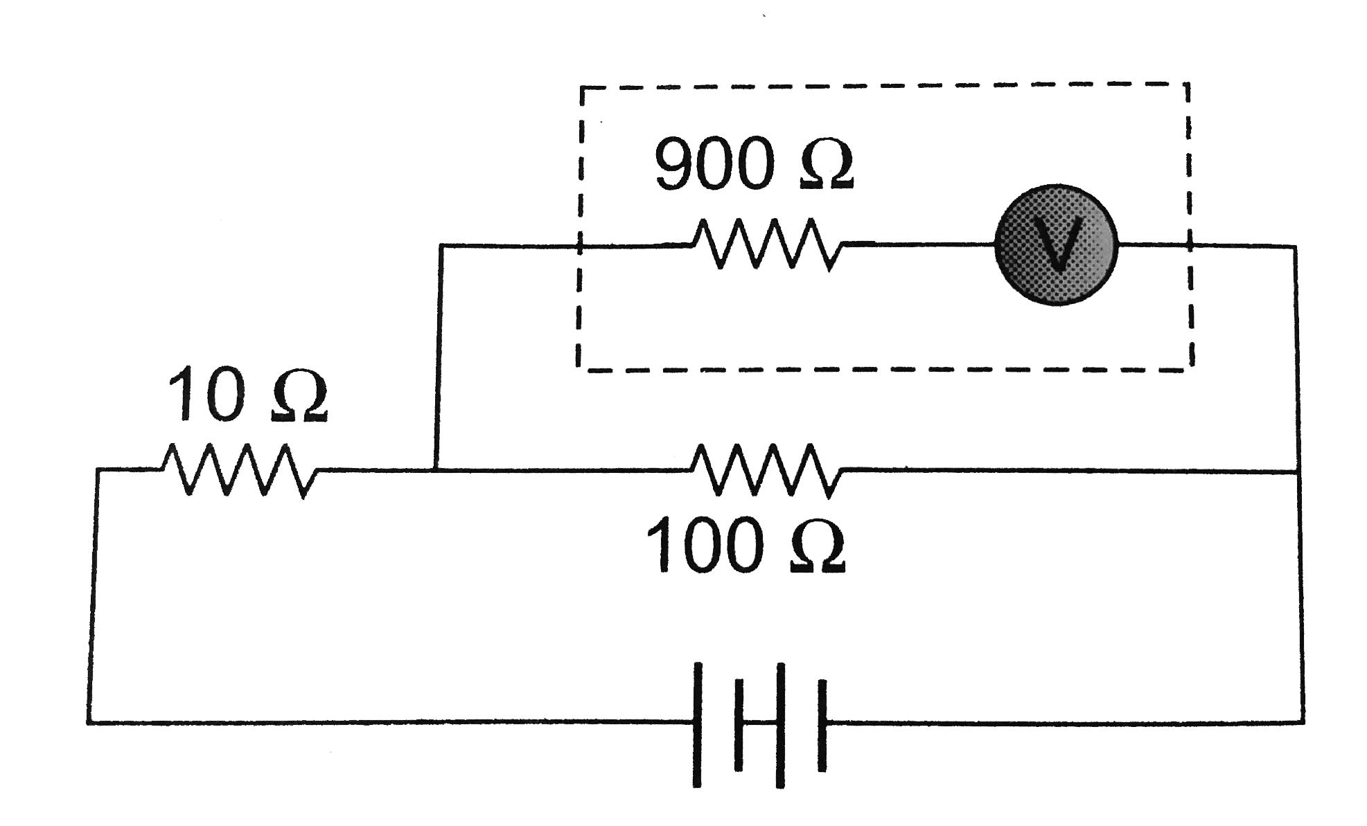
The potential difference across the `100 Omega` resistance in the following circuit is measured by a voltmeter of `900 Omega` resistance. The percentage error made in reading the potential difference is
 05:39View Solution
A voltmeter with resistance `2500 Omega` indicates a voltage of `125 V` in the circuit shown in figure. What is the series resistance to be connected ot voltmeter so that it indicates `100 V`? Consider ideal battery.
 03:57View Solution
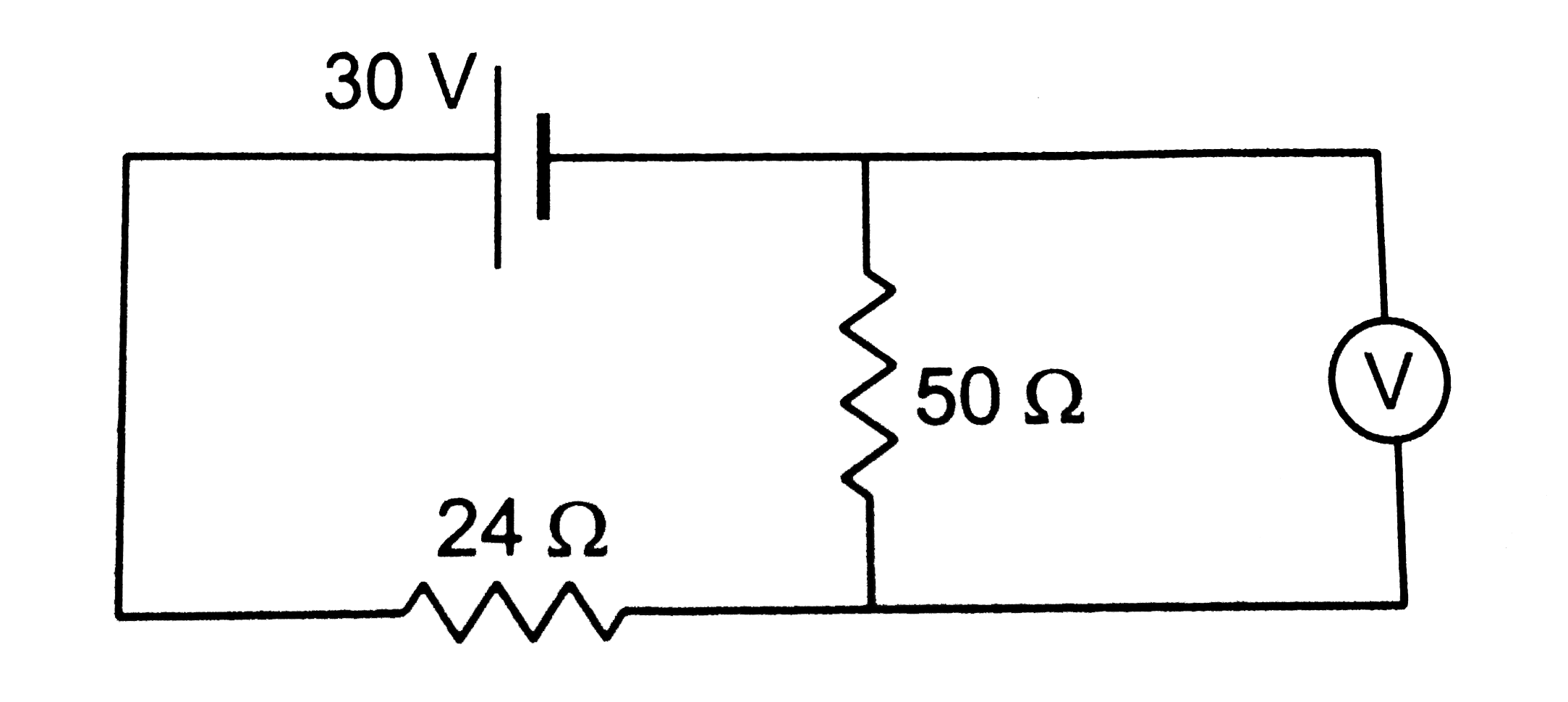
The voltmeter shown in figure reads 18V across the `50(Omega)`resistor. Find the resistance of the voltmeter.
 07:34View Solution
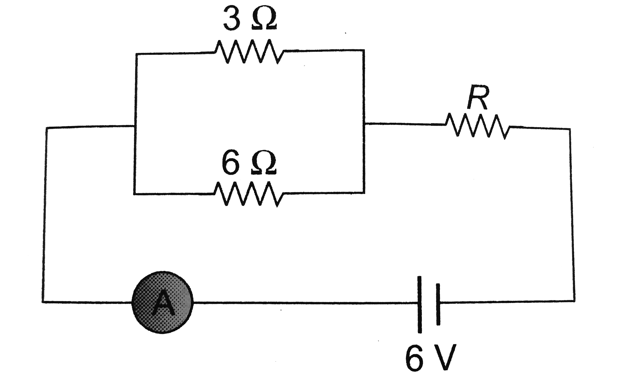
If tha ammter in the given circuit reads `2 A`, the resistance `R` is
 01:50View Solution
Two ammeters, 1 and 2 have different internal resistances: `r_(1)` (known) and `r_(2)` (known). Each ammeter has scale such that the angular deviation of the needle for zero is proportional to the current passing through it. Initially, the ammeters are connected in series to a source of constant voltage. The deviations of the needles of the ammeter are `theta_(1)` and `theta_(2)`, respecitively. The ammeters are then connected in parallel ot the same voltage source. This time, the deviations of the needles are `theta'_(1)` and `theta'_(2)` respectively. Find `r_(2)` in terms of `r_(1), theta_(1), theta_(2), theta'_(1)` and `theta'_(2)`.
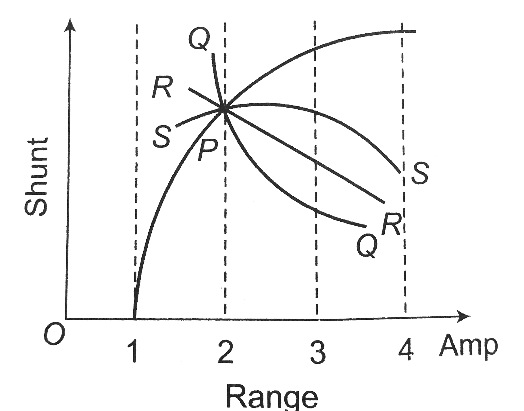
05:49View SolutionThe ammeter has range 1 ampere without shunt. The range can be varied by using different shunt resistance. The graph between shunt resistance and range will have the nature
 02:26View Solution
Ammeter And Voltmeter questions and complete solutions for chapter CURRENT ELECTRICITY of A2Z PHYSICS (HINGLISH) of Class 12
All Exercises from A2Z Class 12 PHYSICS CURRENT ELECTRICITY
- AIIMS Questions
- AIPMTNEET Questions
- Ammeter And Voltmeter
- Assertion- Reason
- Combination And Resistivity
- Heating Effect Of Current
- Kircoff'S Laws And Simple Circuits
- Potentiometer And Meter Bridge
- Problems Based On Mixed Concepts
- R-C Circuits
- Resistivity And Drift Velocity
- Section - A
- Section - C
- Section B - Assertion Reasoning
- Section D - Chapter End Test