Complete Solutions to Exercises (linked Compreshension) of chapter INDUCTANCE of Class 12 book with complete answers and questions
| Class 12 | PHYSICS |
| Chapter | INDUCTANCE |
| CENGAGE PHYSICS | Exercises (linked Compreshension) |
| Number Of Questions | 36 |
| Academic Year | 2023-24 |
A long solenoid of radous `R` has `n` turns of wire per unit length and carries a time-varying current that varies sinusiodally as `I = I_(max) cos omegat`, where `I_(max)` is the maximum current and `omega` I the angular frequancy of the alternating current source (shows in Fig.)
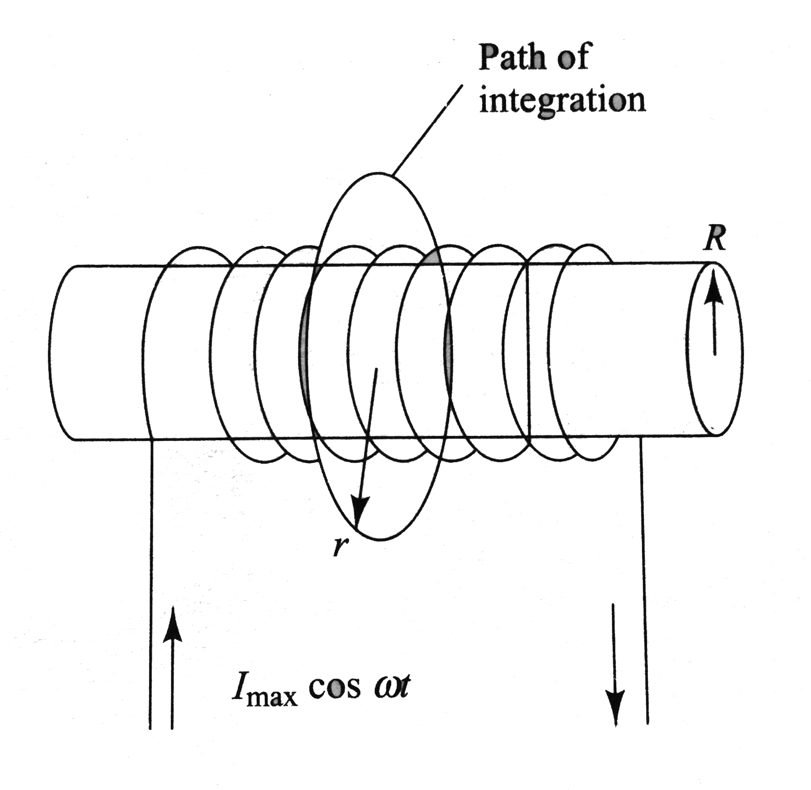
The magnitude of the induced electric field inside tha solenoid, a distance `r lt R` from its long central axis is
View SolutionA long solenoid of radous `R` has `n` turns of wire per unit length and carries a time-varying current that varies sinusiodally as `I = I_(max) cos omegat`, where `I_(max)` is the maximum current and `omega` I the angular frequancy of the alternating current source (shows in Fig.)
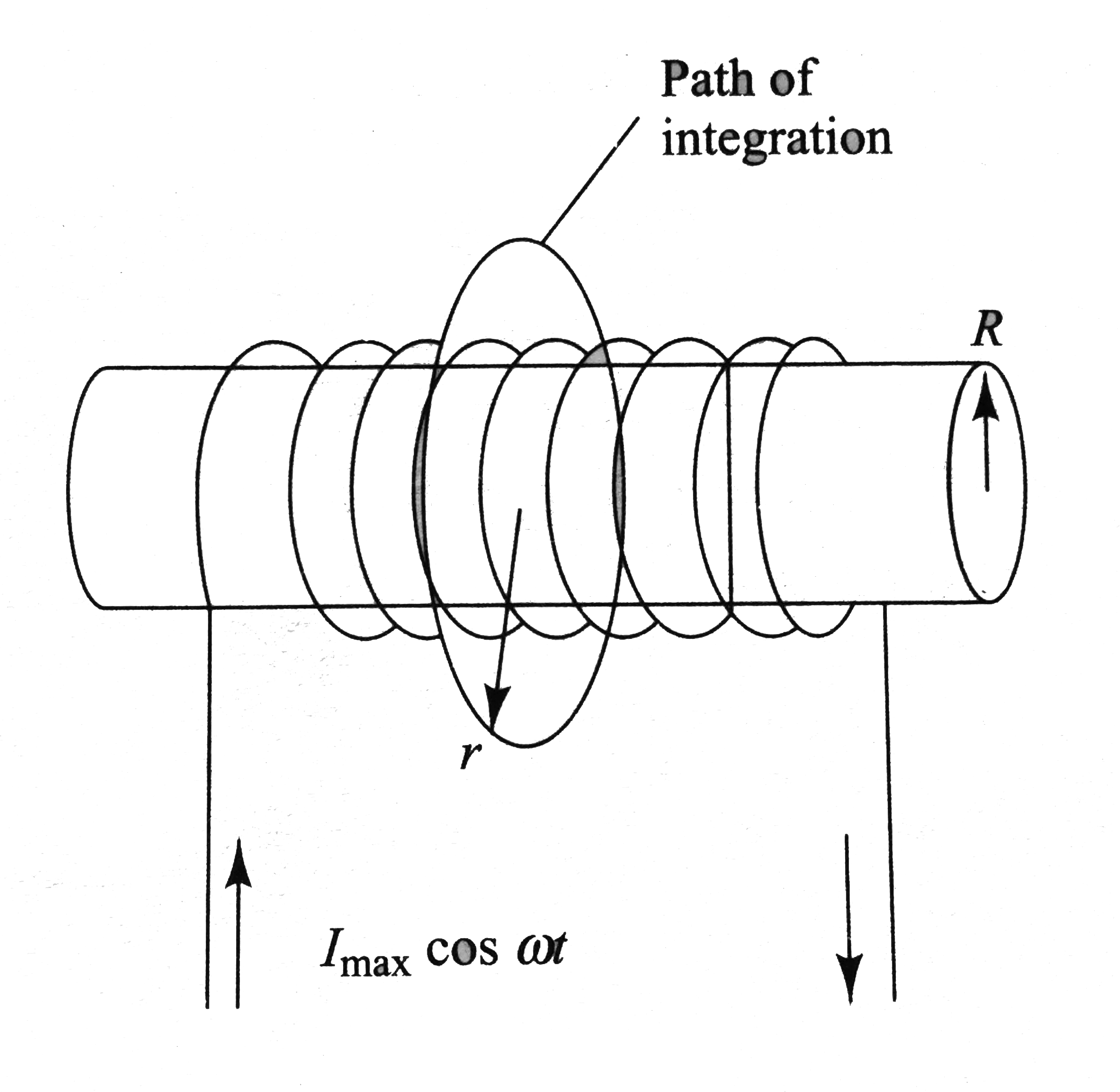
The magnitude of electric field outside the solenoid at a distance `r gt R` from its long central axis is
View SolutionIn the Figure shown `i_1=10e^(-2t) A, i_2=4A` and `V_C=3e^(-2t)V`. Determine
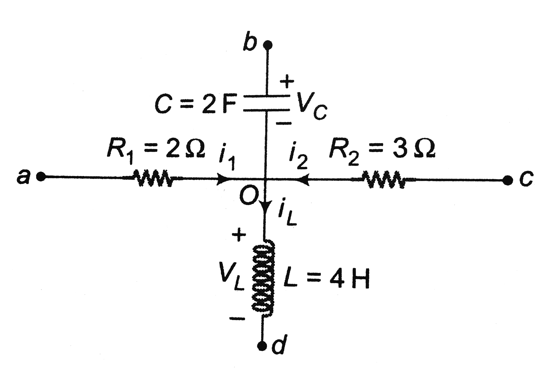
a. `i_L` and `V_L` b. `V_(ac), V_(ab), V_(cd)`
View SolutionIn Fig `i_(1) = 10e^(-2t) A`, `i_(2) = 4 A`, and `V_(C) = 3e^(-2t) V`.
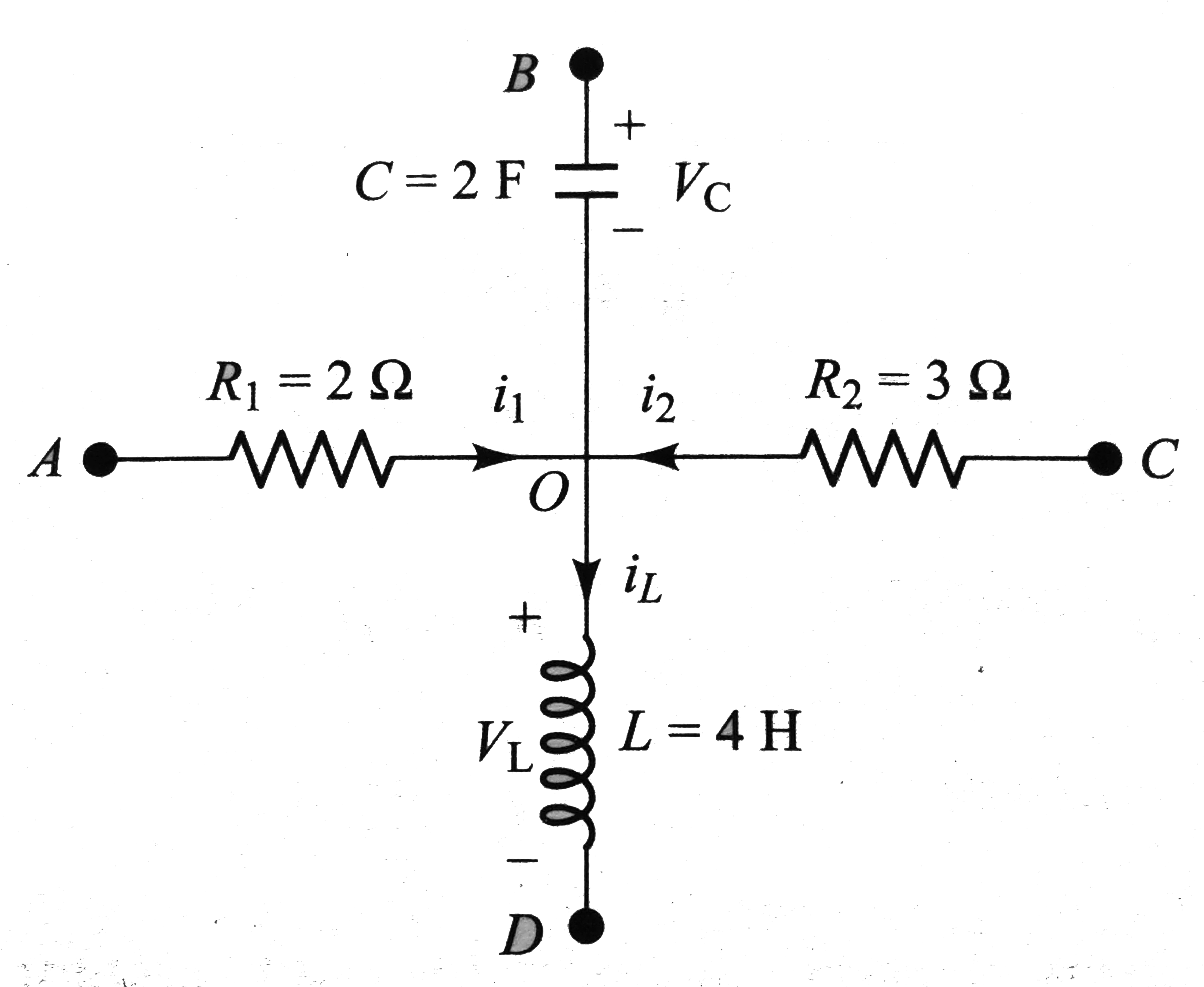
The variation of current in the inductor with time can be represented as
View SolutionIn the Figure shown `i_1=10e^(-2t) A, i_2=4A` and `V_C=3e^(-2t)V`. Determine

a. `i_L` and `V_L` b. `V_(ac), V_(ab), V_(cd)`
View SolutionIn Fig `i_(1) = 10e^(-2t) A`, `i_(2) = 4 A`, and `V_(C) = 3e^(-2t) V`.
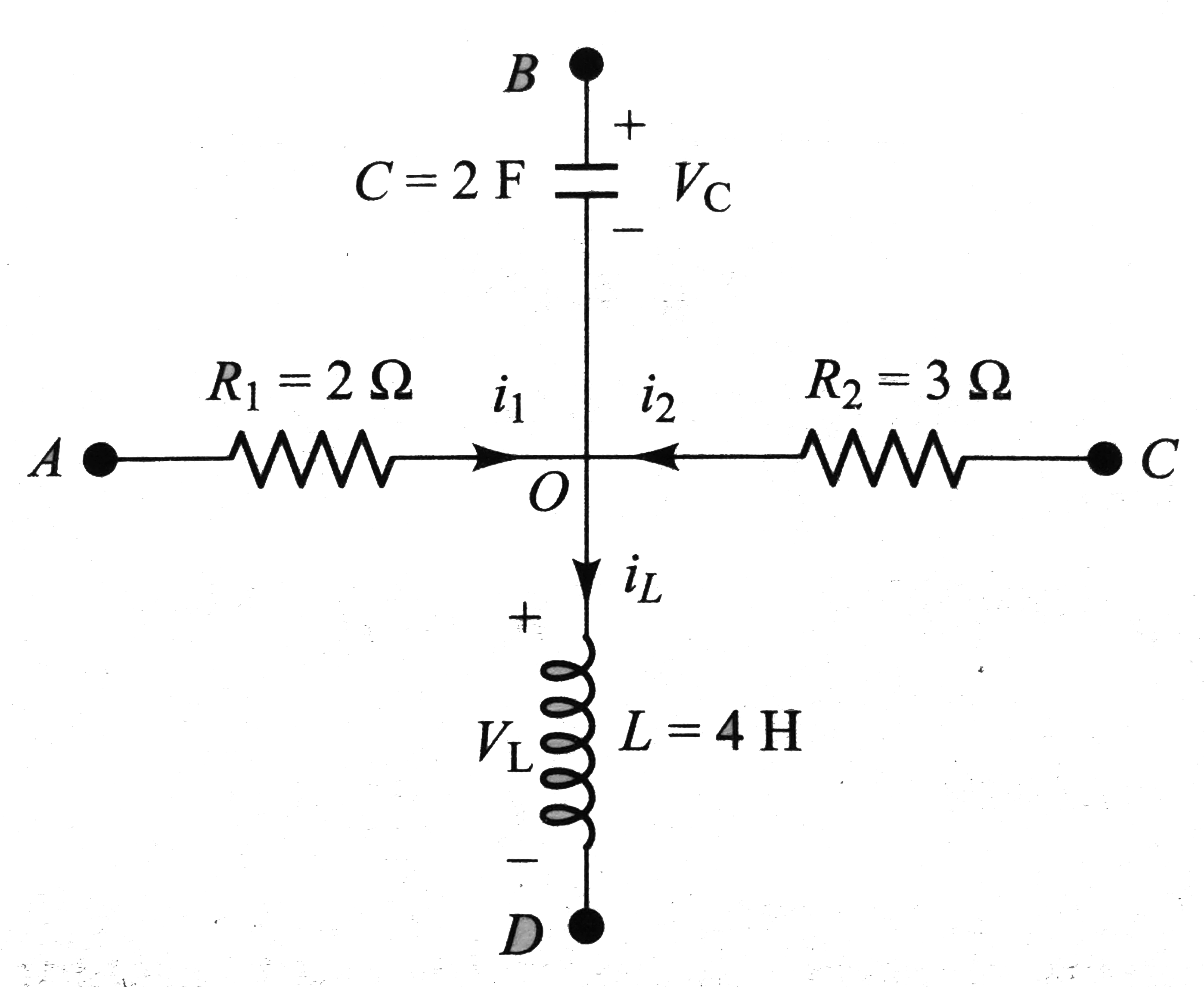
the vartiation of potential difference across `A` and `C(V_(AC))` with time can be respresented as
View SolutionIn the Figure shown `i_1=10e^(-2t) A, i_2=4A` and `V_C=3e^(-2t)V`. Determine

a. `i_L` and `V_L` b. `V_(ac), V_(ab), V_(cd)`
View SolutionIn Fig `i_(1) = 10e^(-2t) A`, `i_(2) = 4 A`, and `V_(C) = 3e^(-2t) V`.
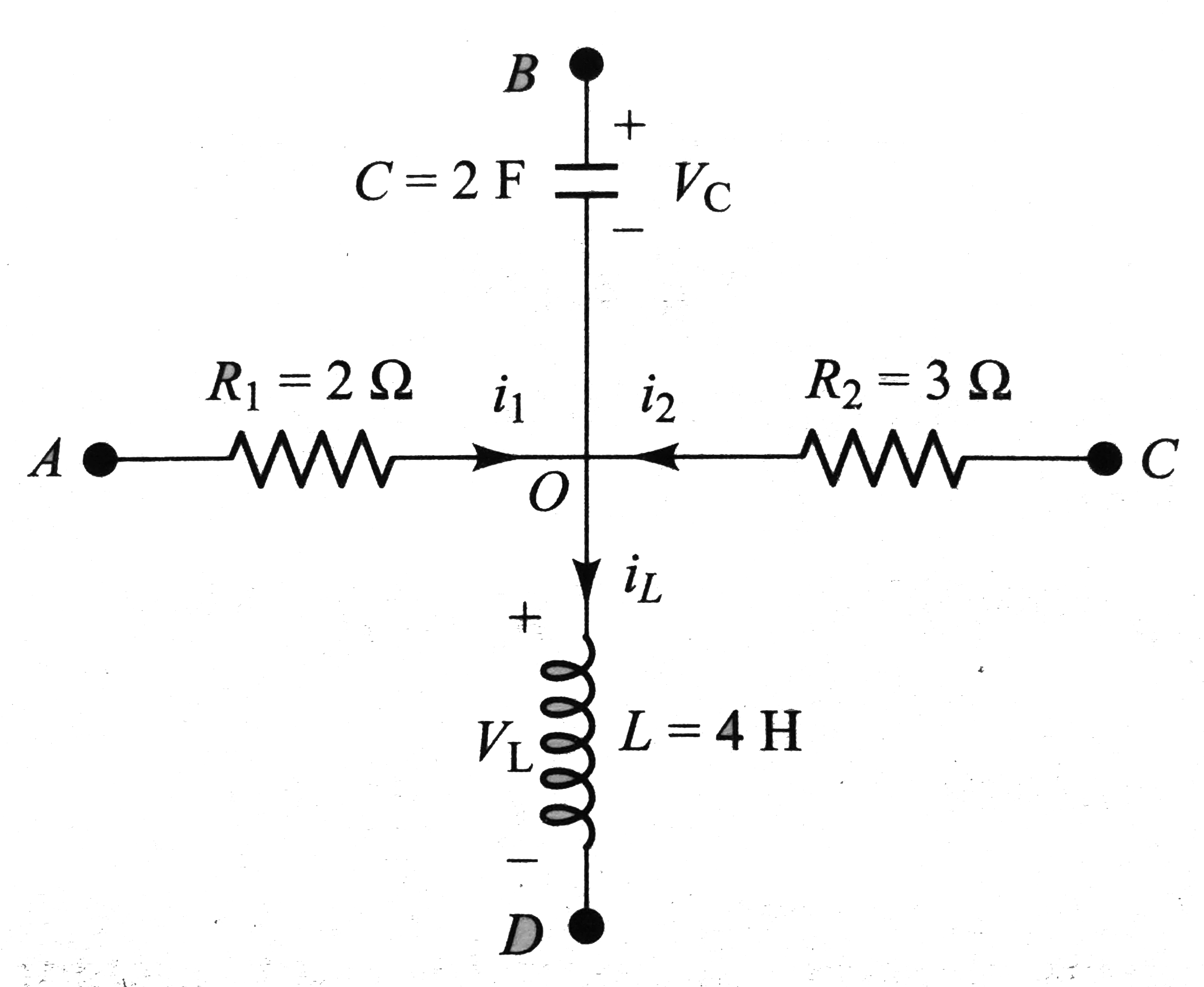
The variation of potential difference across `C` and `D(V_(CD))` with time can be expressed as
View SolutionIn the circuit shows (Fig.) switches `S_(1)` and `S_(3)` have been closed for `1 s` and `S_(2)` remained open. Just after `1 s`, switch `S_(2)` is closed and `S_(1)` and `S_(3)` are opened. Find after that instant `(t = 0)`:
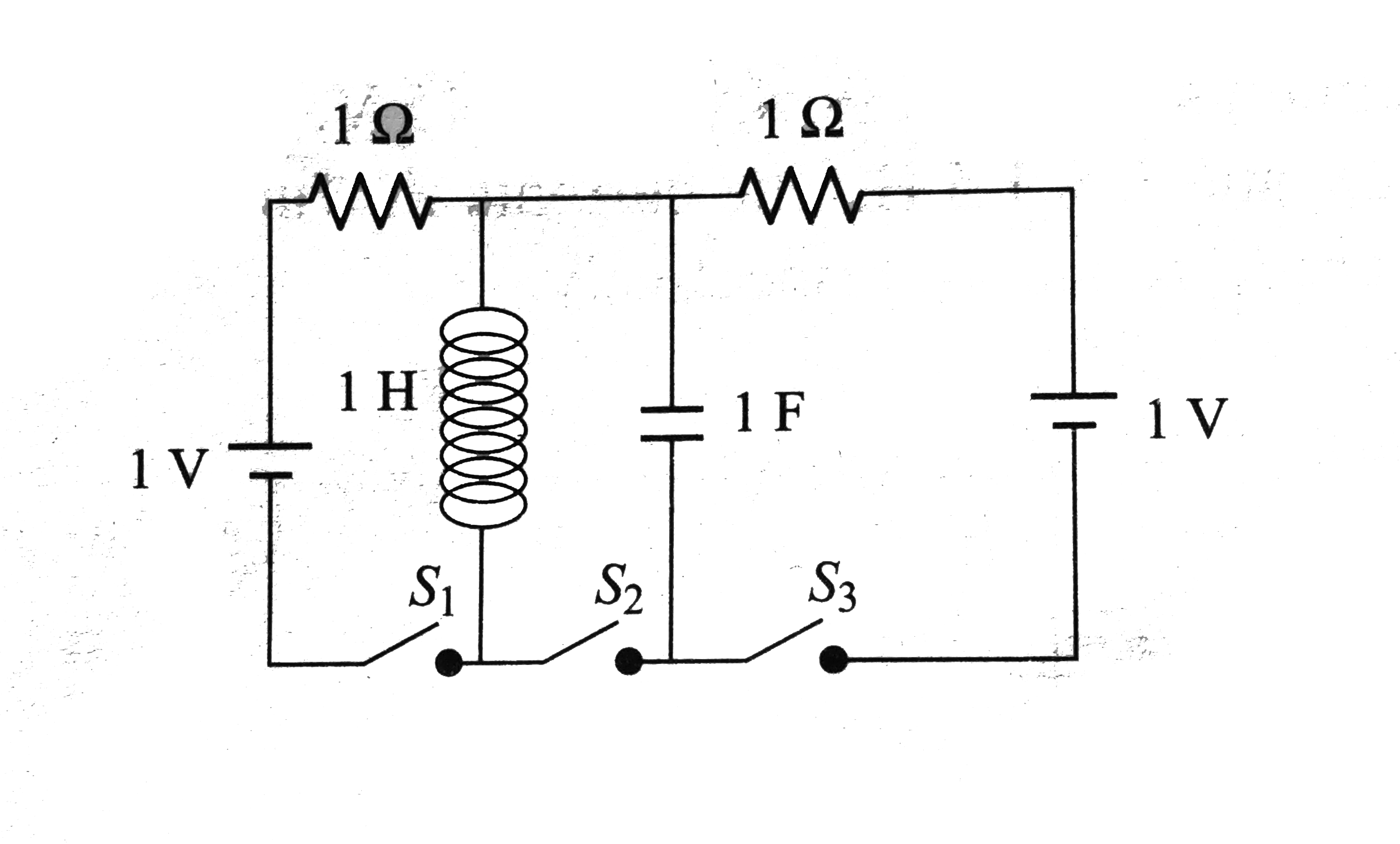
the maximum current in the circuit containing inductor and capacitor (only `S_(2)` is closed)
View SolutionIn the circuit shows (Fig.) switches `S_(1)` and `S_(3)` have been closed for `1 s` and `S_(2)` remained open. Just after `1 s`, switch `S_(2)` is closed and `S_(1)` and `S_(3)` are opened. Find after that instant `(t = 0)`:
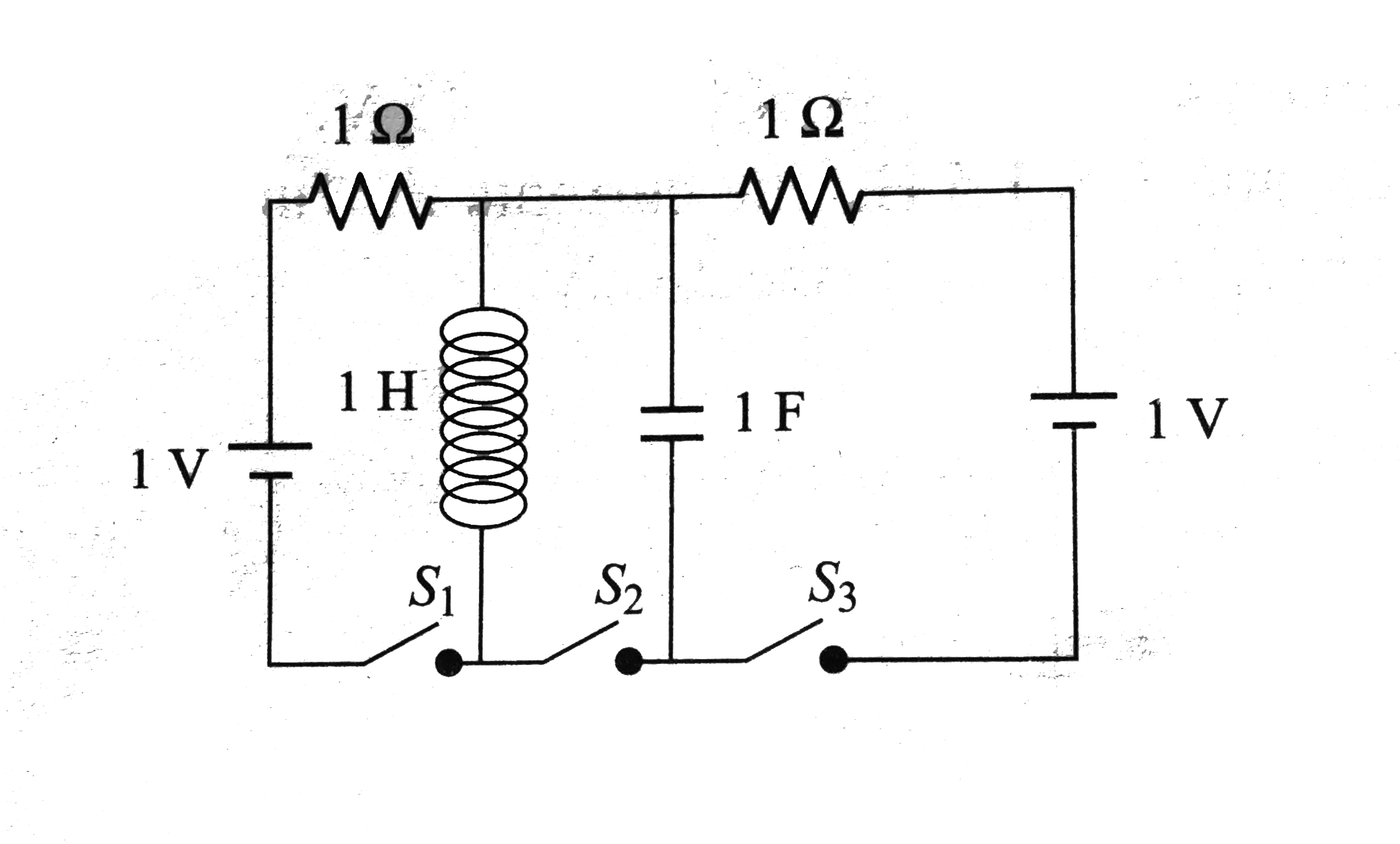
the maximum charge on the capacitor
View SolutionIn the circuit shows (Fig.) switches `S_(1)` and `S_(3)` have been closed for `1 s` and `S_(2)` remained open. Just after `1 s`, switch `S_(2)` is closed and `S_(1)` and `S_(3)` are opened. Find after that instant `(t = 0)`:
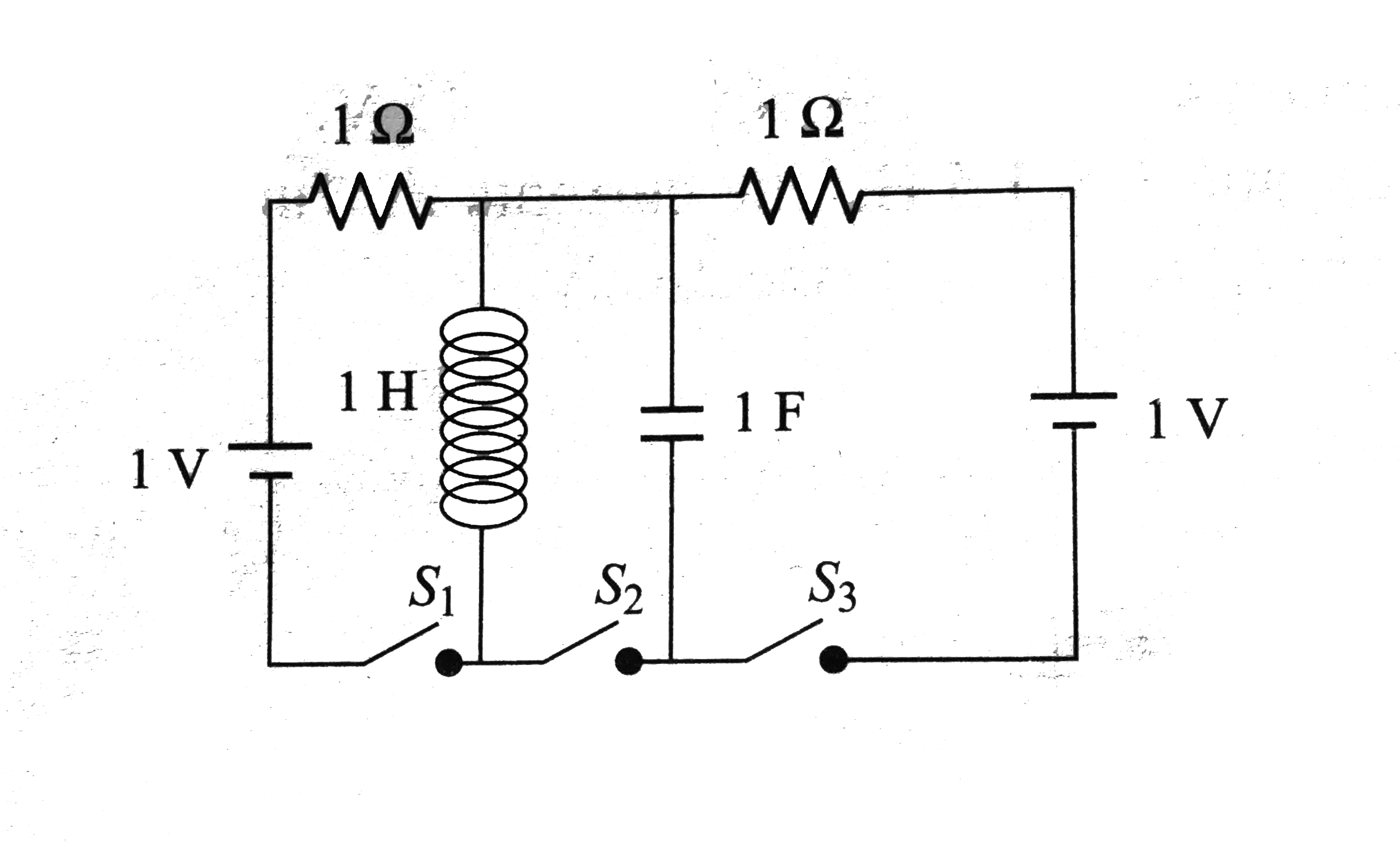
the charge on the upper plate of the capacitor as a funtion of time
View SolutionIn the given (Fig.) all the symbols have their usual meanings. At `t = 0`, key `K` is closed. Now answer the following questions.
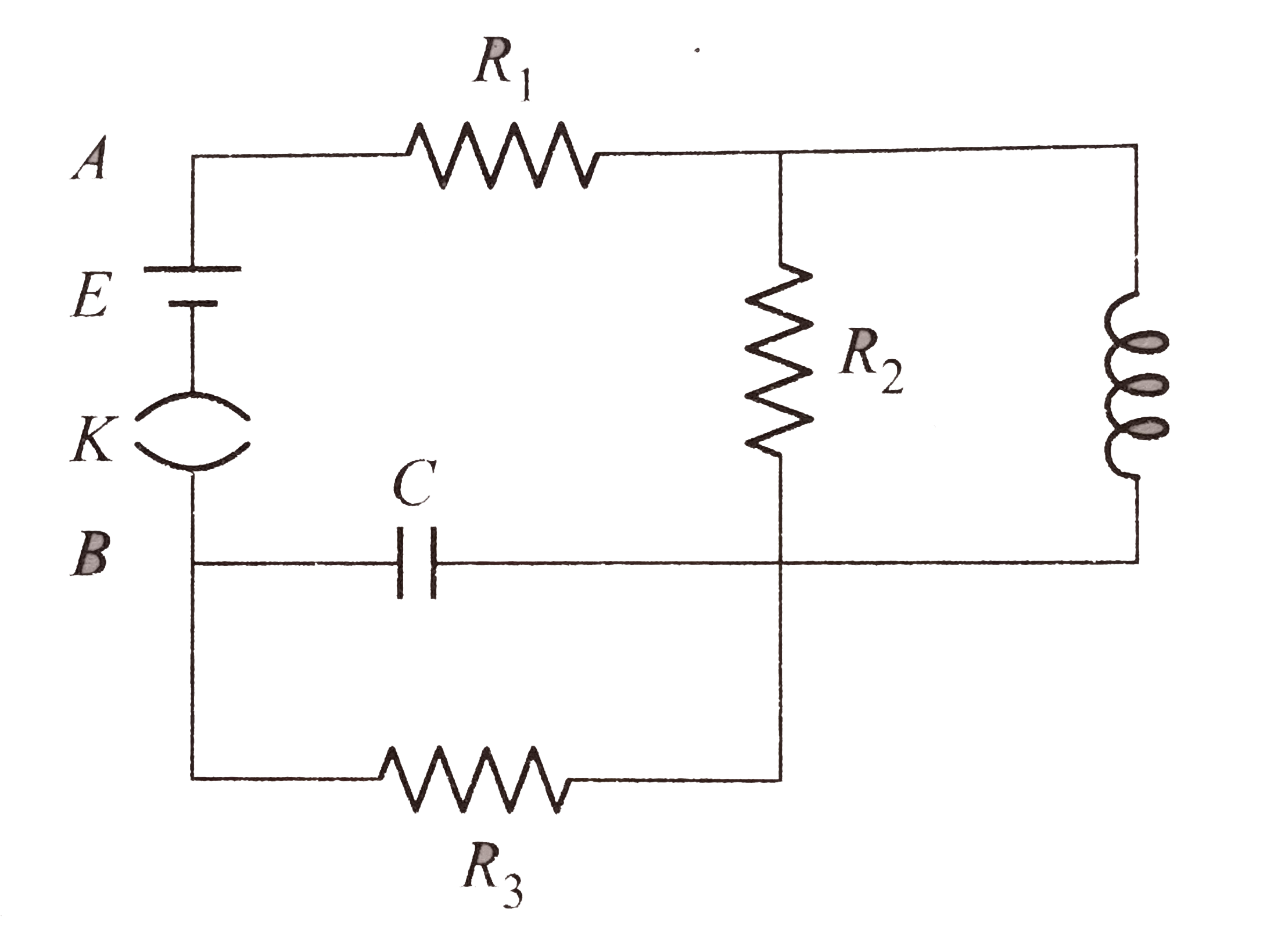
At `t = 0`, the euivalent resistance between `A` and `B` is
View SolutionIn the given (Fig.) all the symbols have their usual meanings. At `t = 0`, key `K` is closed. Now answer the following questions.
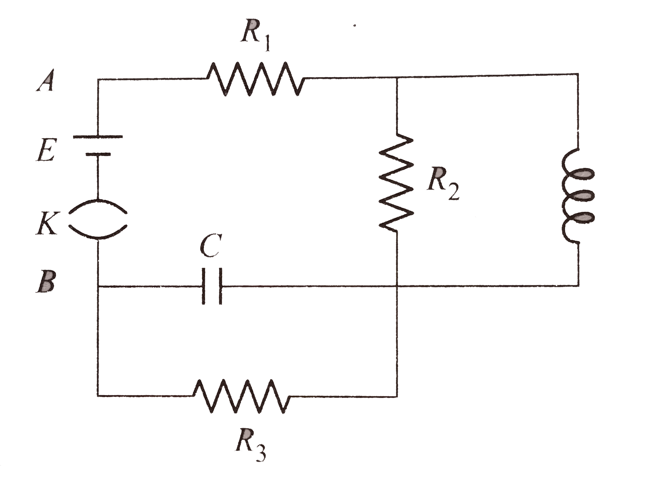
At `t rarr oo`, the euivalent resistance between `A` and `B` is
View SolutionIn the circuit shows in Fig `E = 15 V`, `R_(1) = 1Omega`, `R_(2) = 1 Omega`, `R_(3) = 2Omega`, and `L = 1.5 H`. The currents flowing through `R_(1),R_(2)`,and `R_(3)` are `i_(1),i_(2)`, and `i_(3)`, respectively.
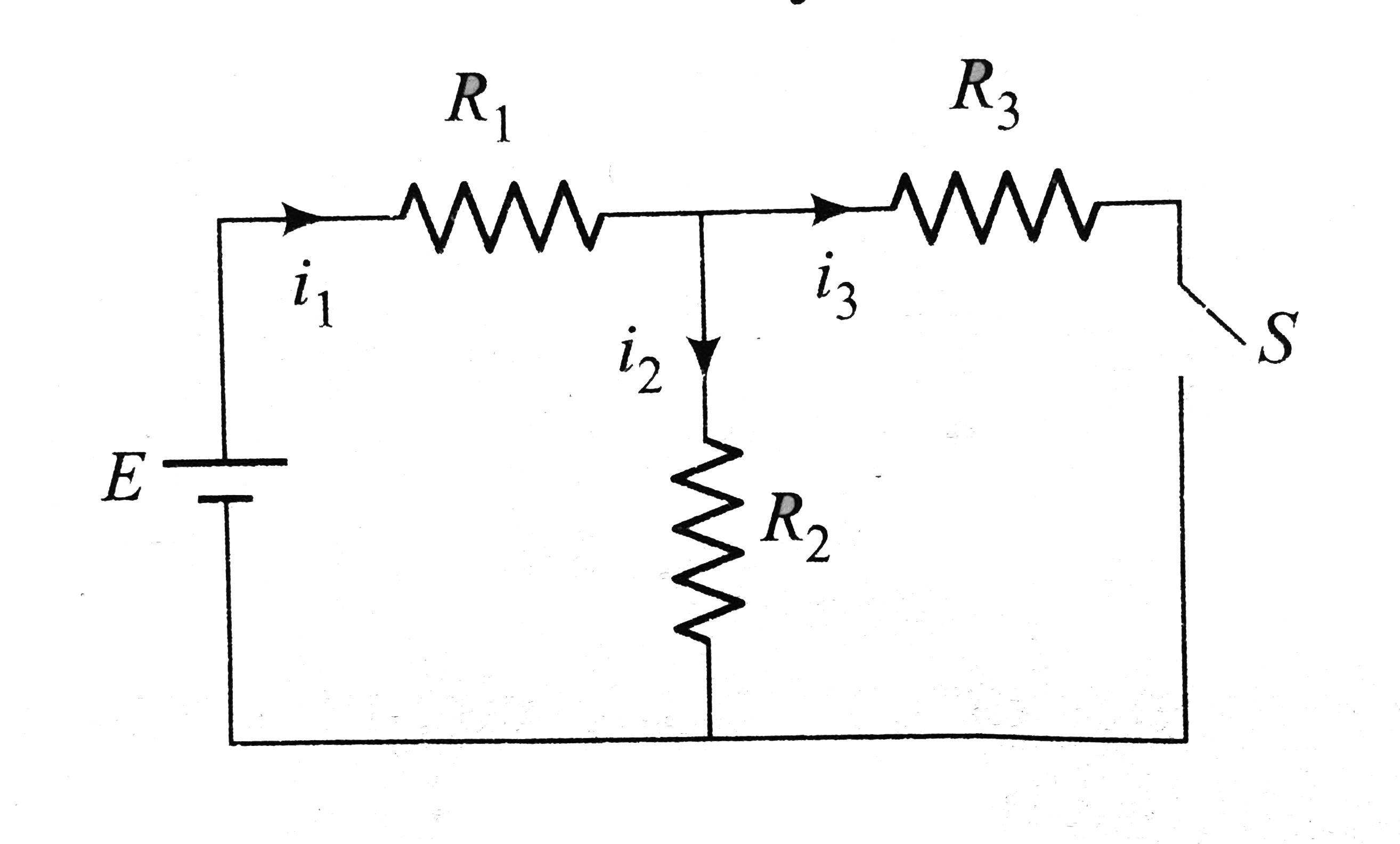
Immediately after tuning switch `S` on,
View SolutionIn the circuit shows in Fig `E = 15 V`, `R_(1) = 1Omega`, `R_(2) = 1 Omega`, `R_(3) = 2Omega`, and `L = 1.5 H`. The currents flowing through `R_(1),R_(2)`,and `R_(3)` are `i_(1),i_(2)`, and `i_(3)`, respectively.
Immediately after turning switch `S` on,

View SolutionIn the circuit shows in Fig `E = 15 V`, `R_(1) = 1Omega`, `R_(2) = 1 Omega`, `R_(3) = 2Omega`, and `L = 1.5 H`. The currents flowing through `R_(1),R_(2)`,and `R_(3)` are `i_(1),i_(2)`, and `i_(3)`, respectively.
Immediately after turning switch `S` on,

View SolutionIn the given at `t = 0`, switch `S` is closed.
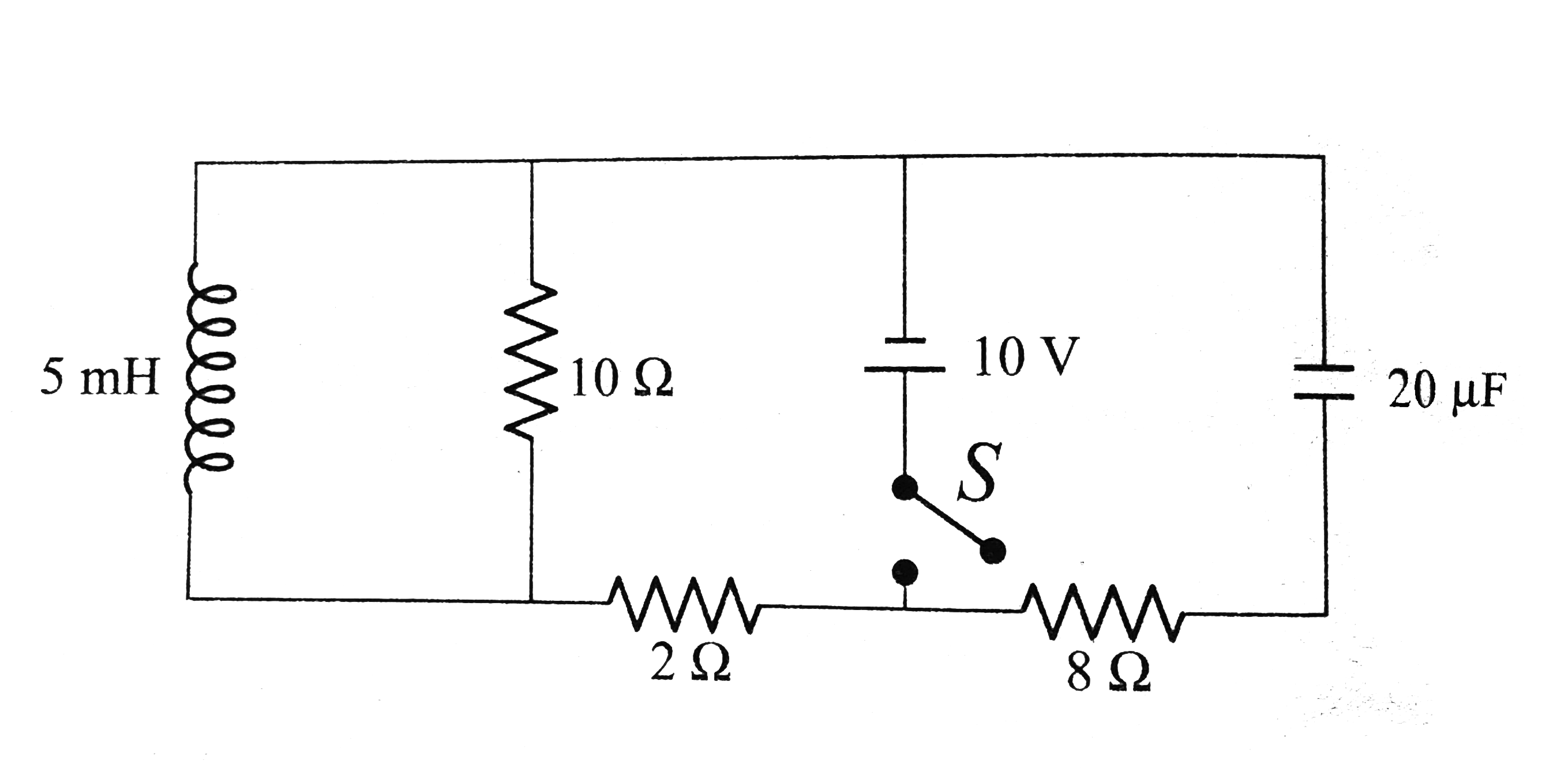
The current through the `10 Omega` resistor at any instant `t(0 lt t lt oo)` will be
View SolutionIn the given at `t = 0`, switch `S` is closed.
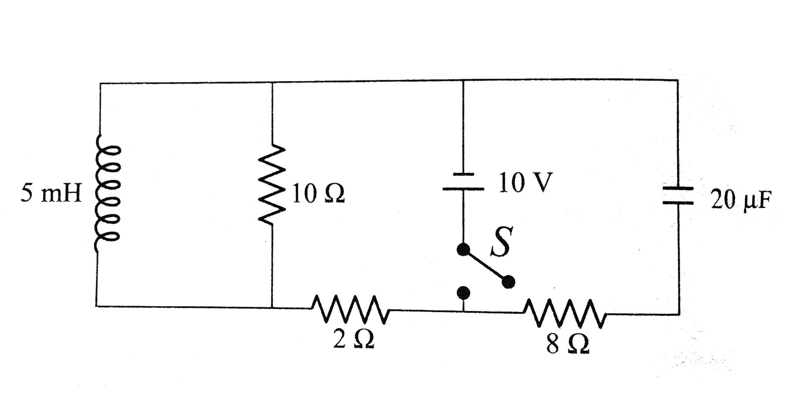
The energy stored in the inductor at any instant `t (0 lt t oo)` will be
View SolutionIn the given at `t = 0`, switch `S` is closed.
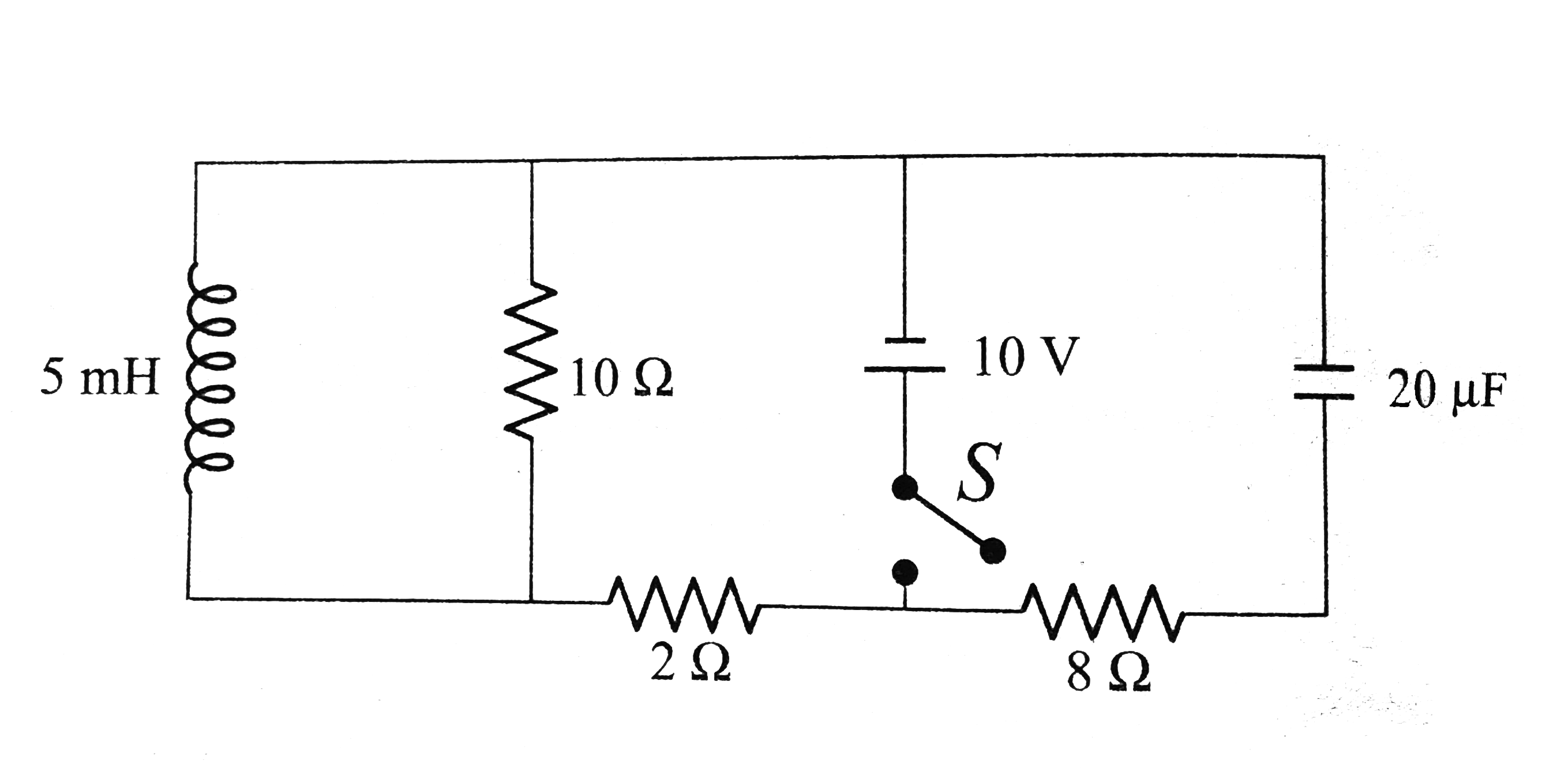
The energy stored in the capacitor and inductor, respectively, at `t rarr oo` will be
View SolutionIn Fig. there is a frame consisting of two square loops having resistors and inductors as shown. This frame is placed in a uniform but time-varying magnetic field in such a way that one of the loops is placed in crossed magentic field and the other is placed in dot magnetic field. Both magnetic fields are perpendicular to the planes of the loops.
If the magnetic field is given by `B = (20 + 10 t) Wb m^(-2)` in both regions `[l = 20 cm, b = 10 cm`, and `R = 10 Omega`, `L = 10 H`),
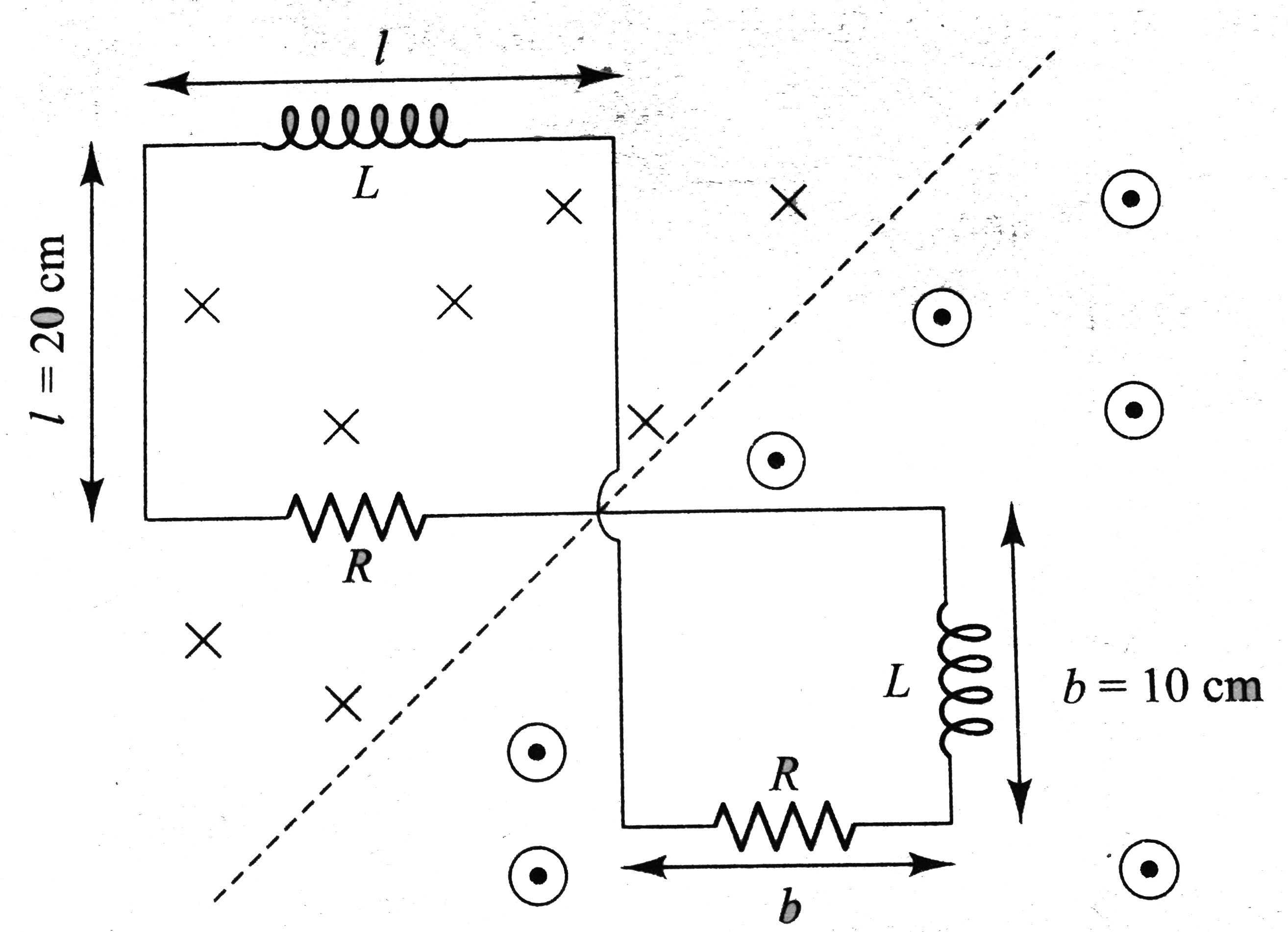
The direction in induced current in the bigger loop will be
View SolutionIn Fig. there is a frame consisting of two square loops having resistors and inductors as shown. This frame is placed in a uniform but time-varying magnetic field in such a way that one of the loops is placed in crossed magentic field and the other is placed in dot magnetic field. Both magnetic fields are perpendicular to the planes of the loops.
If the magnetic field is given by `B = (20 + 10 t) Wb m^(-2)` in both regions `[l = 20 cm, b = 10 cm`, and `R = 10 Omega`, `L = 10 H`),
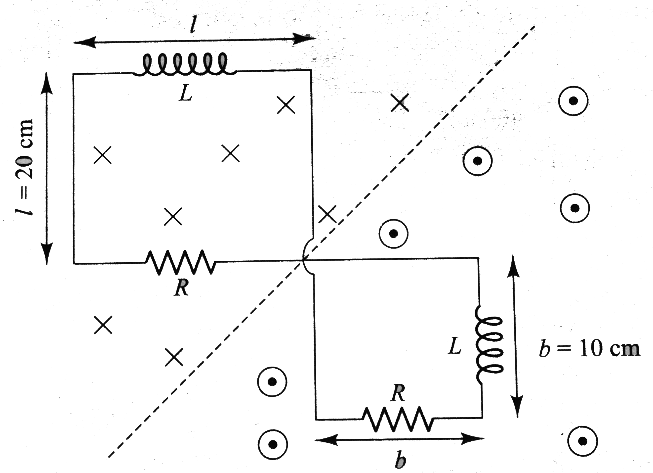
The induced emf in the frame only due to the vartation of magnetic field will be
View SolutionIn Fig. there is a frame consisting of two square loops having resistors and inductors as shown. This frame is placed in a uniform but time-varying magnetic field in such a way that one of the loops is placed in crossed magentic field and the other is placed in dot magnetic field. Both magnetic fields are perpendicular to the planes of the loops.
If the magnetic field is given by `B = (20 + 10 t) Wb m^(-2)` in both regions `[l = 20 cm, b = 10 cm`, and `R = 10 Omega`, `L = 10 H`),
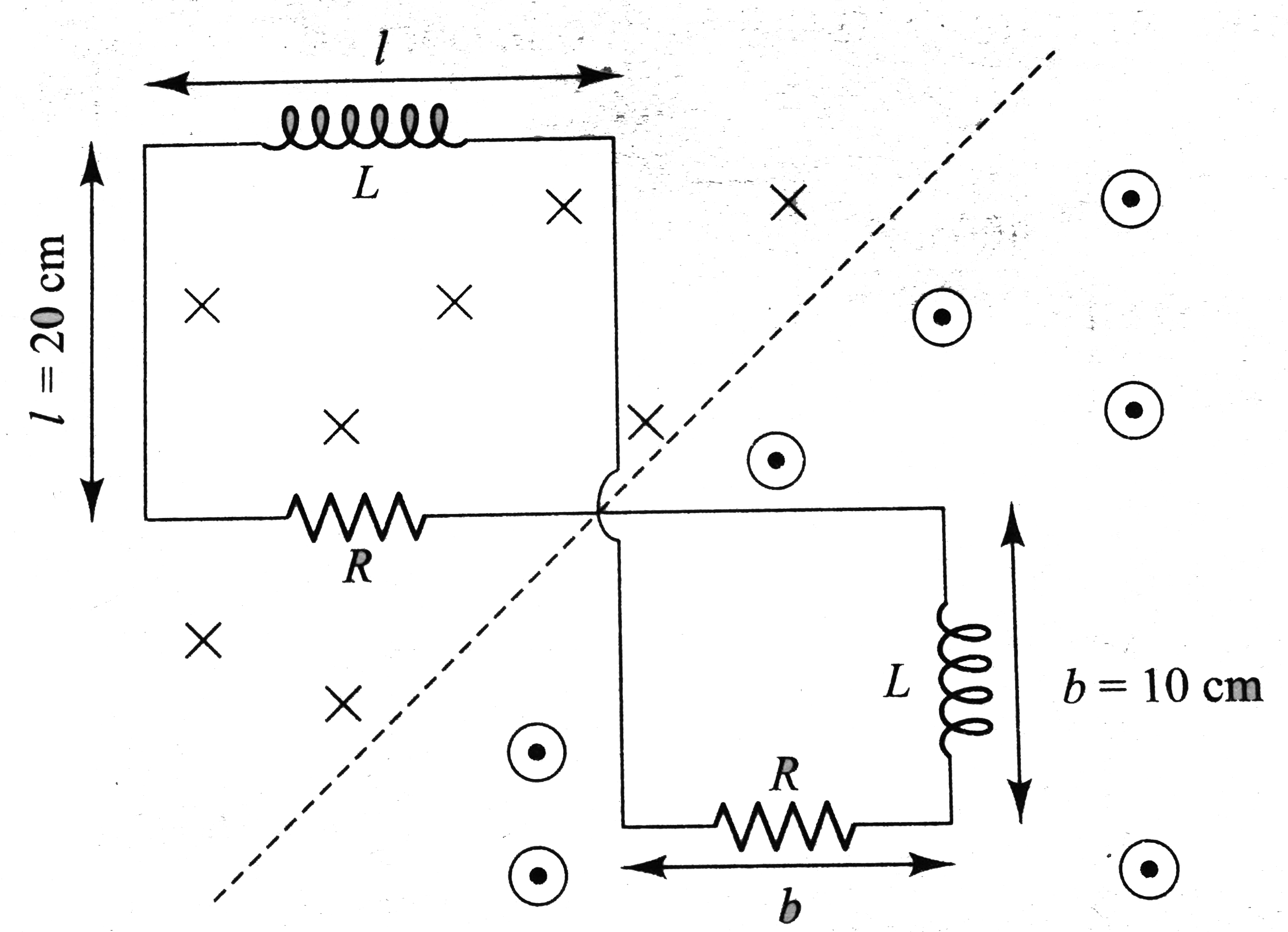
The current in the frame as a funtion of time will be
View Solutionthere in no current part of this circuit for time `t lt o`. Switch `S` is closed at `t = 0`.
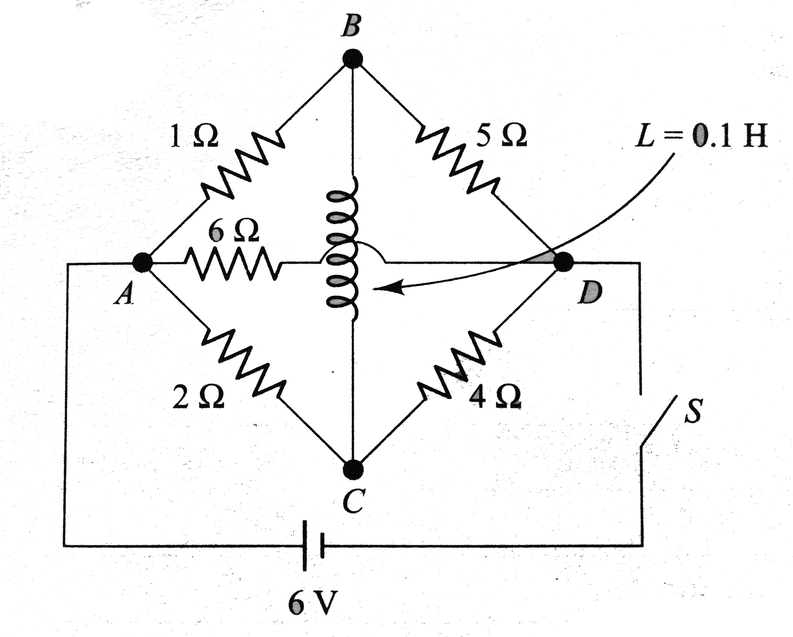
The rate at which the current through the inductor increases initially is
View Solutionthere in no current part of this circuit for time `t lt o`. Switch `S` is closed at `t = 0`.
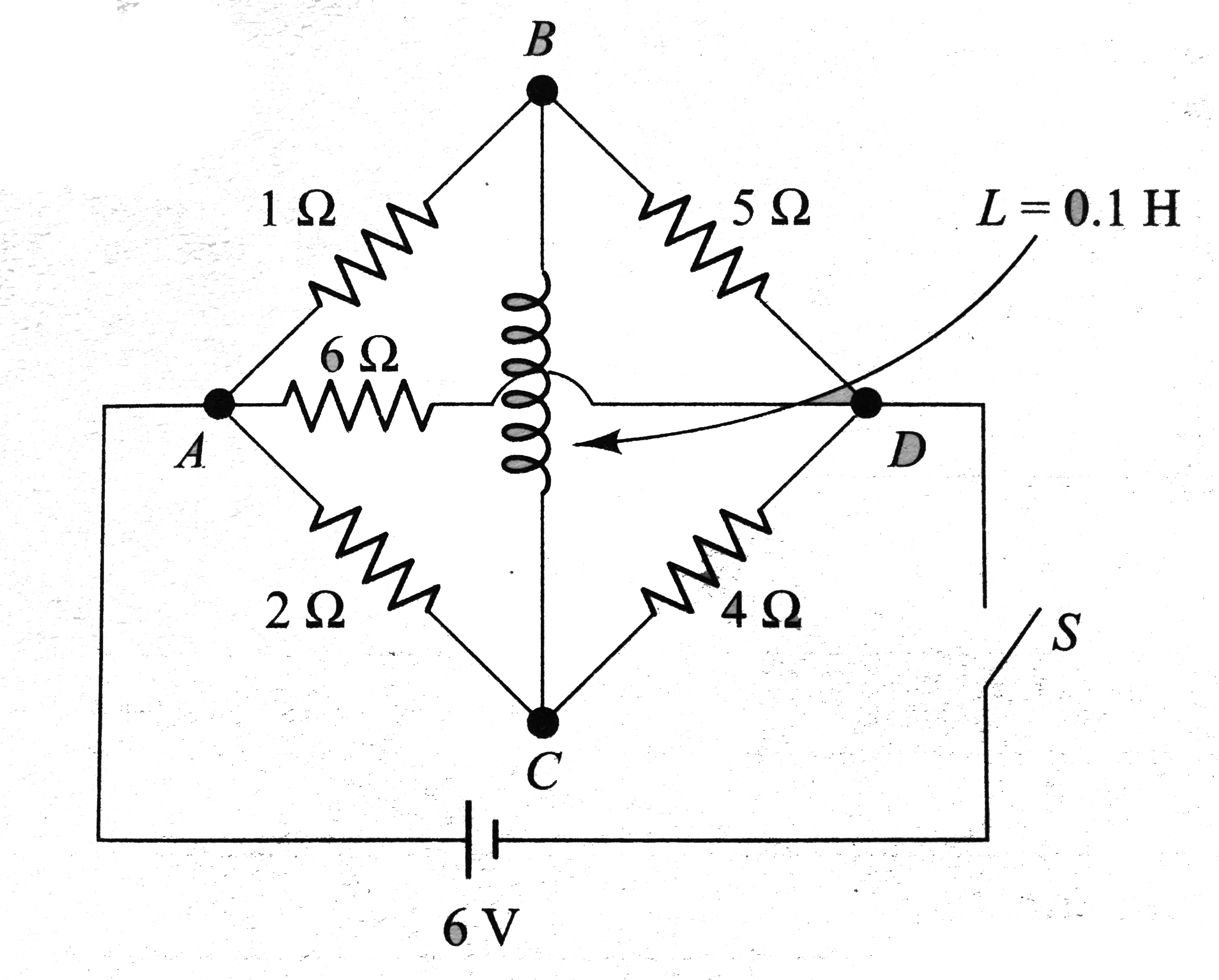
Current through the `6 Omega` resistor
View Solutionthere in no current part of this circuit for time `t lt o`. Switch `S` is closed at `t = 0`.
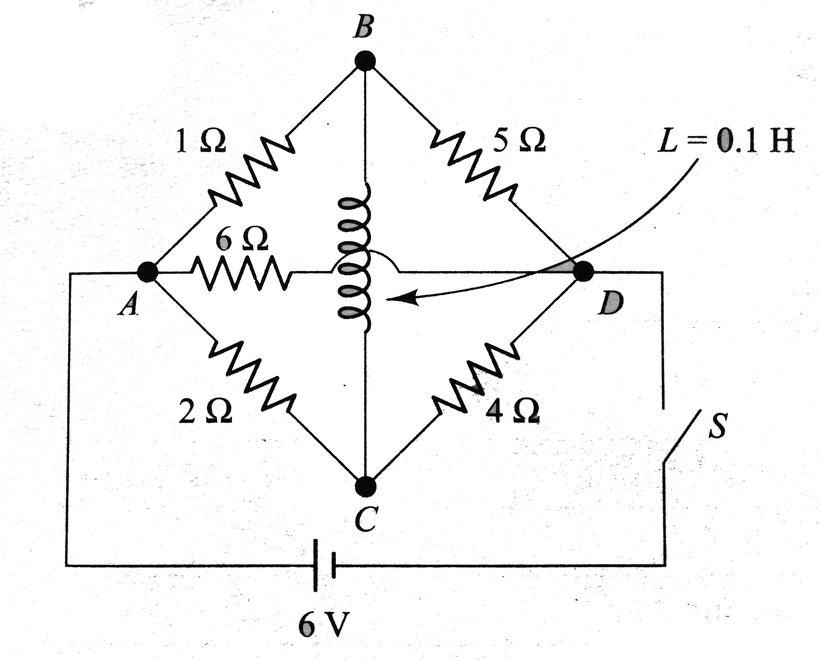
The current through the inductor after a long time will be
View SolutionTwo capacitors of capacitance `C` and `3C` are charged to potential difference `V_(0)` and `2V_(0)`, respectively, and connected to an inductor of inductance `L` as shows in Fig. Initially, the current in the inductor is zero. Now, switch `S` is closed.
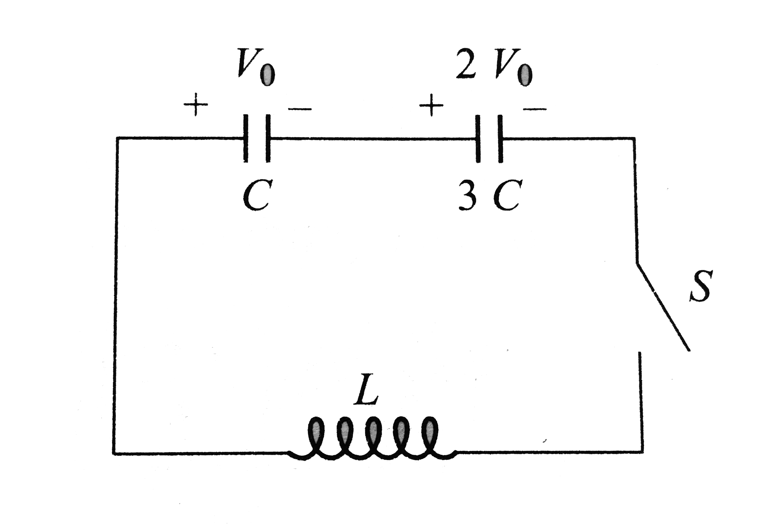
The maximum current in the inductor is
View SolutionTwo capacitors of capacitance `C` and `3C` are charged to potential difference `V_(0)` and `2V_(0)`, respectively, and connected to an inductor of inductance `L` as shows in Fig. Initially, the current in the inductor is zero. Now, switch `S` is closed.
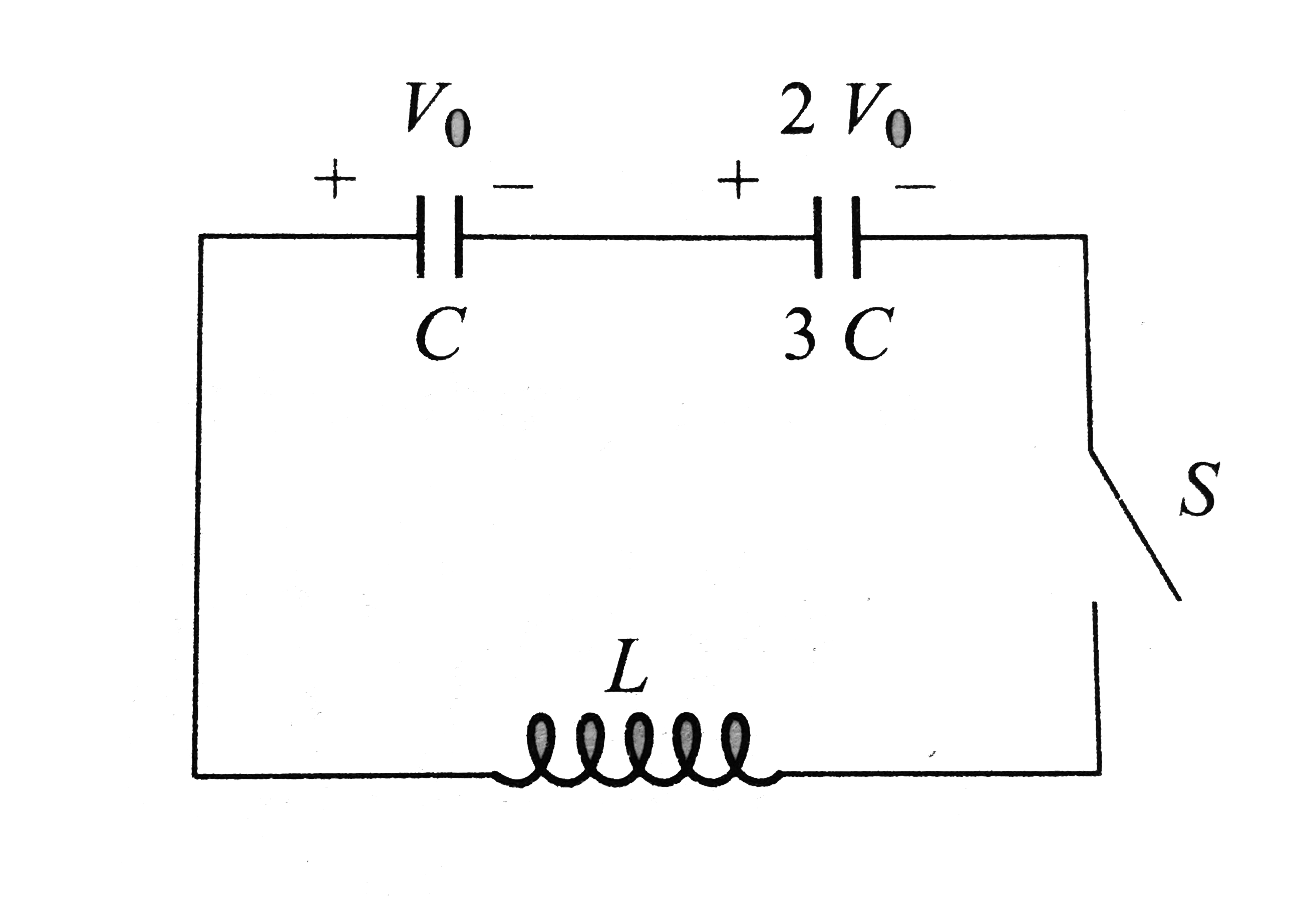
Potential difference across capacitor of capacitance `C` when the current in the circuit is maximum is
View SolutionTwo capacitors of capacitance `C` and `3C` are charged to potential difference `V_(0)` and `2V_(0)`, respectively, and connected to an inductor of inductance `L` as shows in Fig. Initially, the current in the inductor is zero. Now, switch `S` is closed.
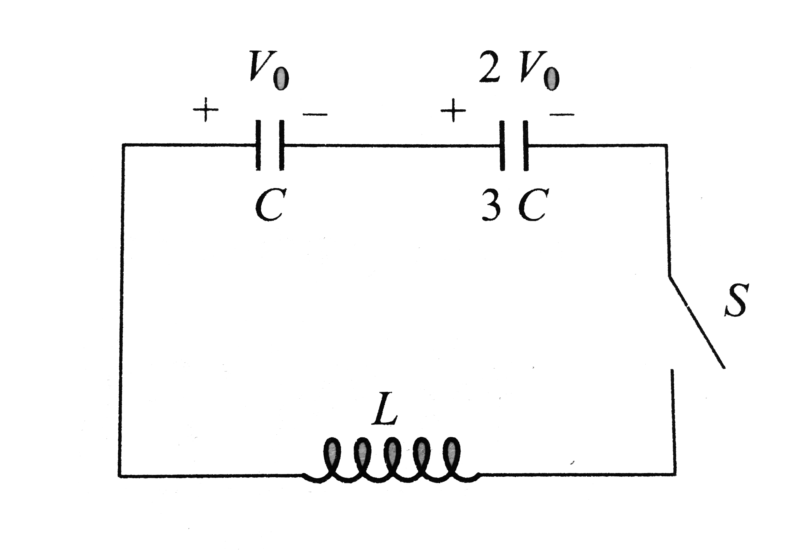
Potential difference across capacitor of capacitance `3C` when the current in the circuit is maximum is
View SolutionIn Fig. there is a conducting loop `ABCDEF` of resistance `lambda` per unit length placed near a long straight current-carrying wire. The dimension are shows in the figure. The long wire lies in the plane of the loop. The current in the long wire varies as `I = I_(0)(t)`.

The mutual inductance of the pair is
View SolutionIn Fig. there is a conducting loop `ABCDEF` of resistance `lambda` per unit length placed near a long straight current-carrying wire. The dimension are shows in the figure. The long wire lies in the plane of the loop. The current in the long wire varies as `I = I_(0)(t)`.
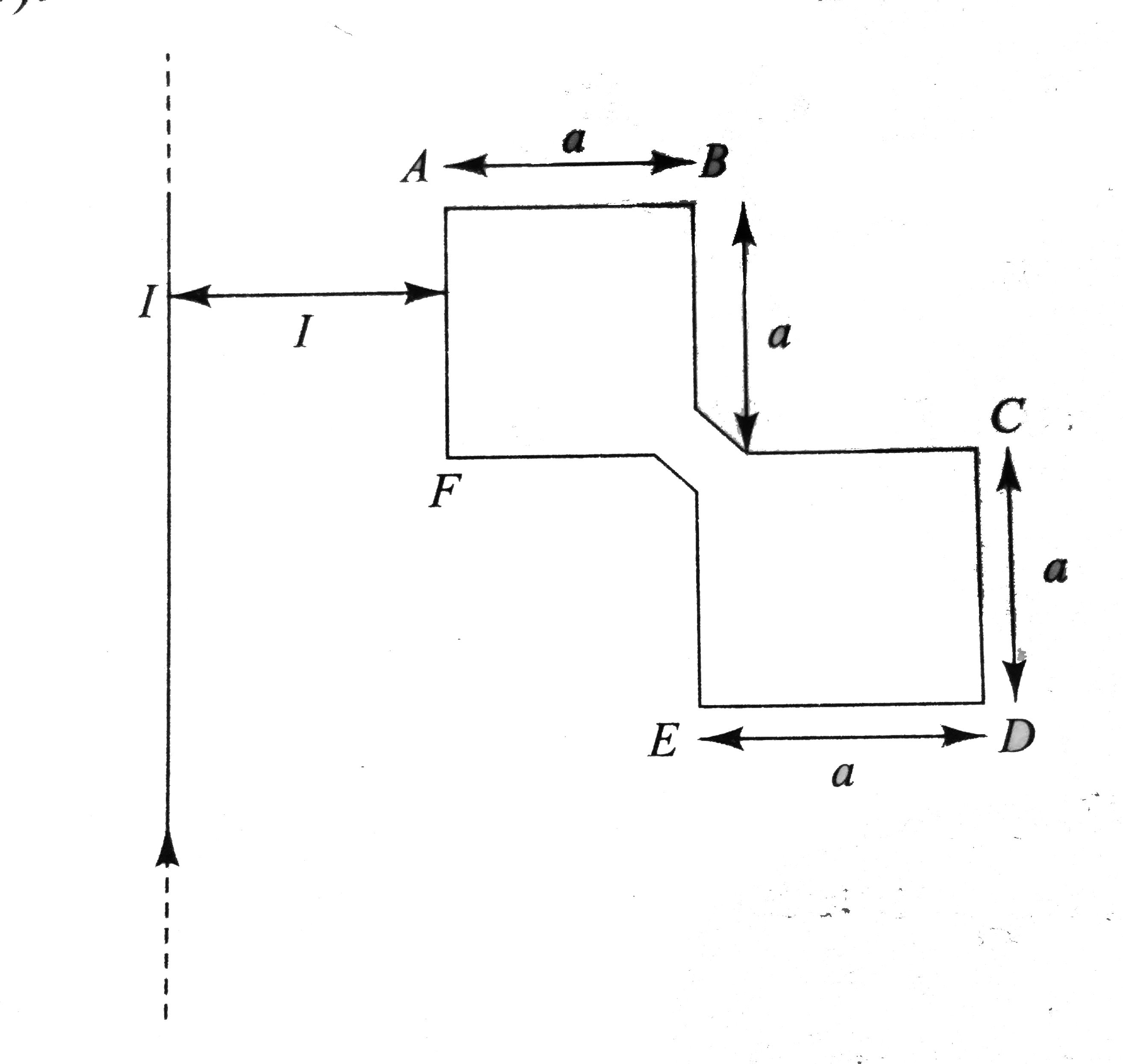
The emf induced in the closed loop is
View SolutionIn Fig. there is a conducting loop `ABCDEF` of resistance `lambda` per unit length placed near a long straight current-carrying wire. The dimension are shows in the figure. The long wire lies in the plane of the loop. The current in the long wire varies as `I = I_(0)(t)`.
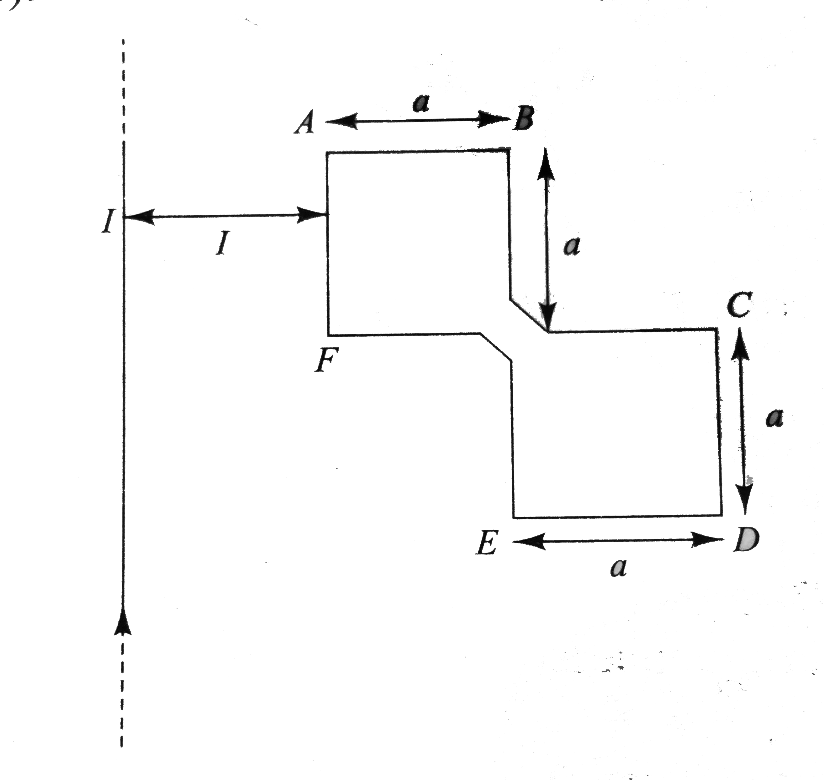
The heat produced in the loop in time `t` is
View SolutionInitially, the capacitor is charged to a potential of `5 V` and then connected to position 1 with the shown polarity for `1 s`. After `1s` it is connected across the inductor at position 2
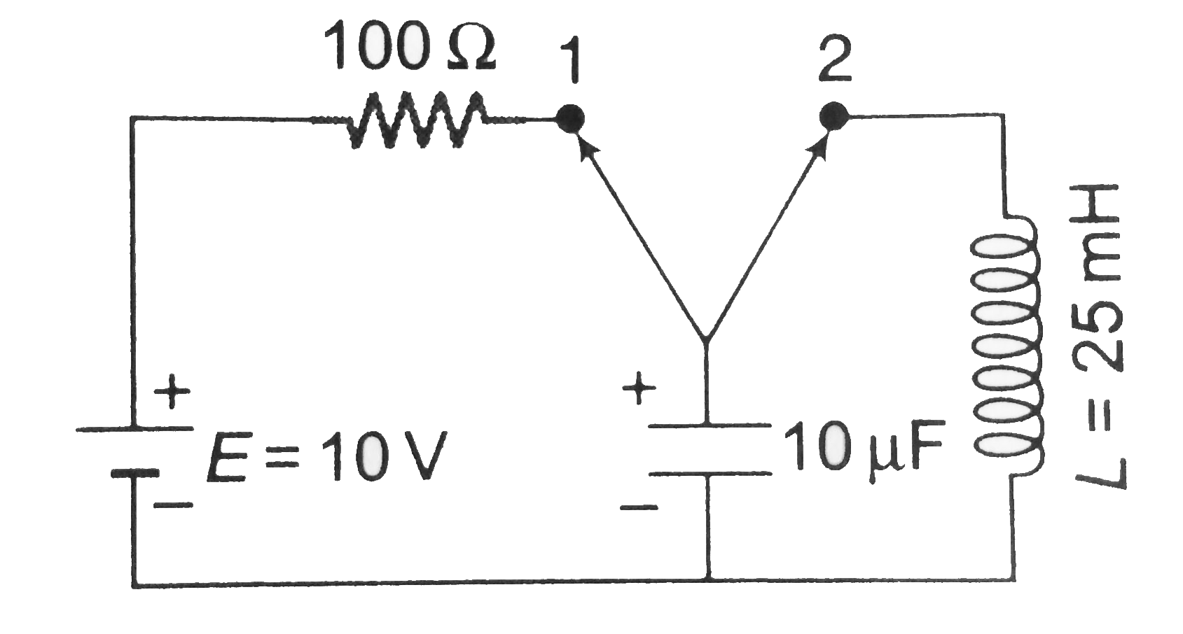
(a) Find the potential across the capacitor after `1 s` of its connection to position 1.
(b) Find the maximum current flowing in the `L- C` circuit when capacitor is connected across the inductor. Also, find the frequency of `LC` oscillations.
View SolutionInitially, the capacitor is charged to a potential of `5 V` and then connected to position 1 with the shown polarity for `1 s`. After `1s` it is connected across the inductor at position 2

(a) Find the potential across the capacitor after `1 s` of its connection to position 1.
(b) Find the maximum current flowing in the `L- C` circuit when capacitor is connected across the inductor. Also, find the frequency of `LC` oscillations.
View SolutionInitially, the capacitor is charged to a potential of `5 V` and then connected to position 1 with the shown polarity for `1 s`. After `1s` it is connected across the inductor at position 2

(a) Find the potential across the capacitor after `1 s` of its connection to position 1.
(b) Find the maximum current flowing in the `L- C` circuit when capacitor is connected across the inductor. Also, find the frequency of `LC` oscillations.
View SolutionIn the circuit in Fig. switch `S_(1)` was closed for a long time . At time `t = 0` the switch is opened.
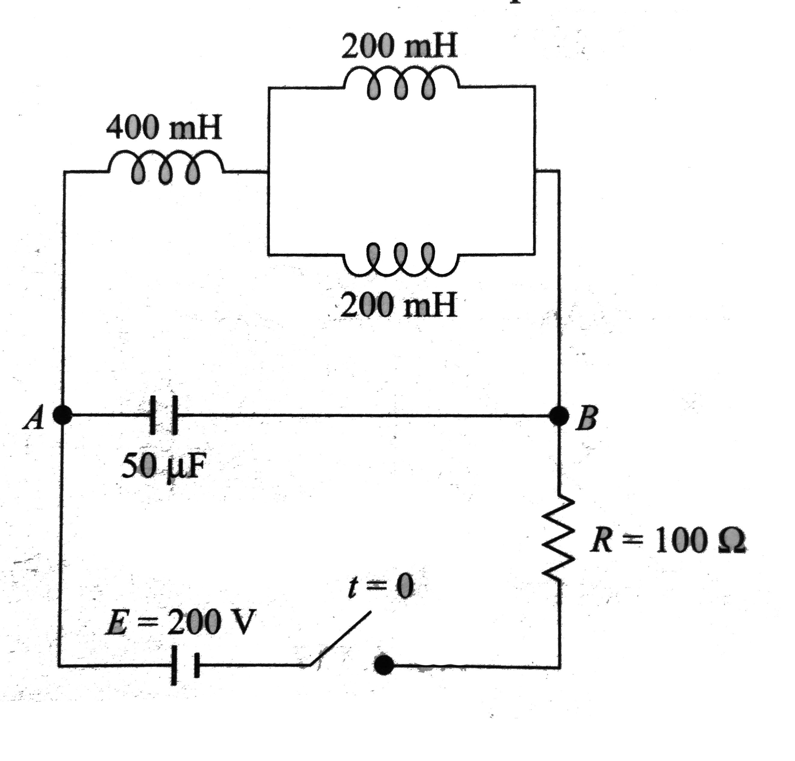
Find the maximum potentail difference across the plates of the capacitor after the switch is opened.
View SolutionIn the circuit in Fig. switch `S_(1)` was closed for a long time . At time `t = 0` the switch is opened.
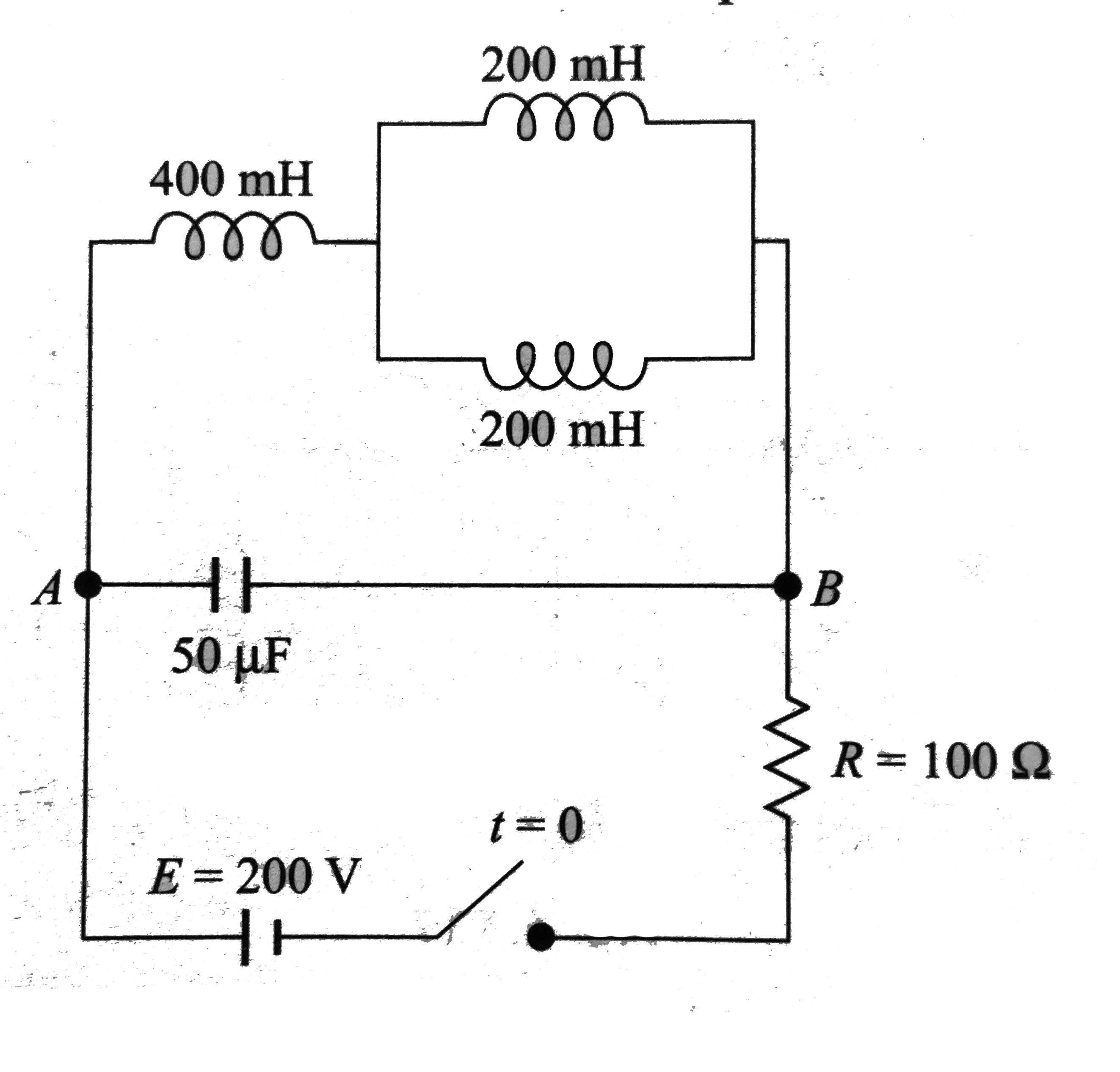
Find the angular frequency of oscillation of the charge on the capacitor.
View Solution
Exercises (linked Compreshension) questions and complete solutions for chapter INDUCTANCE of CENGAGE PHYSICS (ENGLISH) of Class 12
All Exercises from CENGAGE PHYSICS Class 12 PHYSICS INDUCTANCE
- Archives (fills In The Blanks)
- Archives (integer)
- Archives (linked Compreshension)
- Archives (multiple Correct)
- Archives (single Correct )
- Comprehension Type
- Concept Based
- Exercise 4.1
- Exercises (assertion-reasoning)
- Exercises (integer)
- Exercises (linked Compreshension)
- Exercises (multiple Correct )
- Exercises (single Correct )
- Exercises (subjective)
- Illustration
- Multiple Correct Answer
- Single correct Answer Type
- Solved Examples
- Subective Type