Complete Solutions to Illustration of chapter INDUCTANCE of Class 12 book with complete answers and questions
| Class 12 | PHYSICS |
| Chapter | INDUCTANCE |
| CENGAGE PHYSICS | Illustration |
| Number Of Questions | 19 |
| Academic Year | 2023-24 |
A small square loop of wire of side l is placed inside a large square loop of wire of side `L(gtgtl)`. The loops aer coplanar and their centres coincide. What is the mutual inductance of the system?
View SolutionWhat is the mutual inducatance of a system of coaxical cables carrying current in opposite directions a sshows in Fig. 4.3. Their radii are `a` and `b`, respectively.
View SolutionThe equivalent inductance of two inductors is 2.4 H when connected in parallel and 10 H when connected in series. What is the value of inductances of the individual inductors?
View SolutionWhat will happen to the inductance of a solenoid
a. when the number of turns and the length are double keeping the area of cross section same?
b. when the air inside the solenoid is replaced by iron of relative permeability `mu_(r)`?
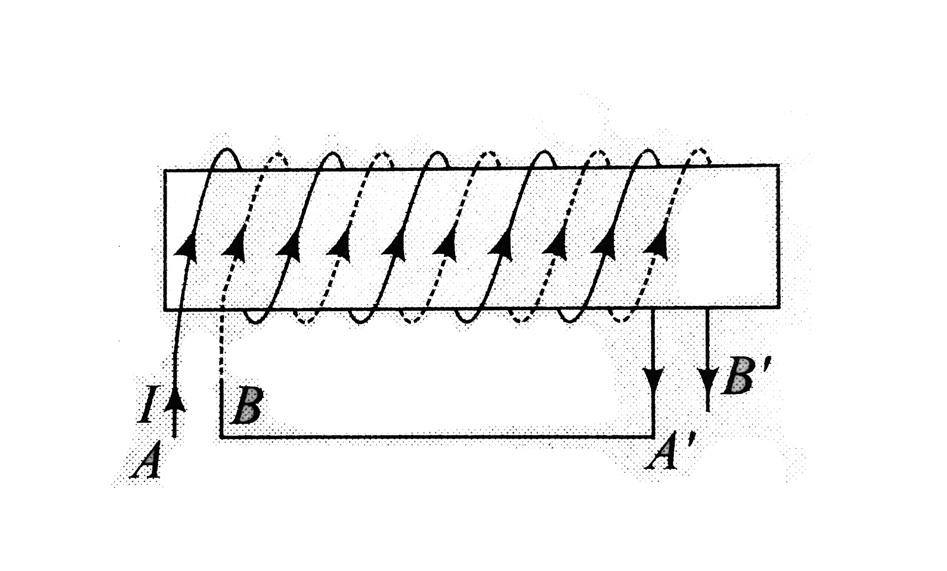
View SolutionIn Fig. coil `1` and coil `2` are wound on a long cylindrical insulator. The ends `A'` and `B` are joined together and current `I` is passed. Self-inductance of the two coils are `L_(1)` and `L_(2)`, and their mutual inductance is `M`.
a. Show that this combination can be replaced by a single coil of equivalent inductange given by
`L_(eq) = L_(1) + L_(2) + 2M`.
b. How could the coils be reconnected by yieldings an equivalent inductance of `L_(eq) = L_(1) + L_(2) - 2M`.
View SolutionThe network shown in the figure is a part of complete circuit. What is the potential difference `V_B-V_A` when the current `I` is `5 A` and is decreasing at a rate of `10^3A//s`?

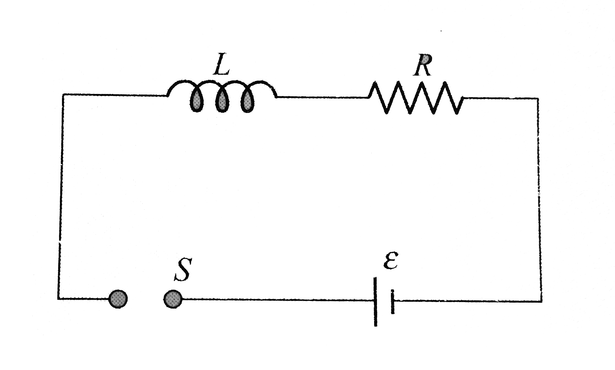
View SolutionIn an `LR` circuit as shows in Fig.when the swtich is closed, how much time will it take for the current to grow to a value `n` times the maximum value of current (where `n lt 1)`?
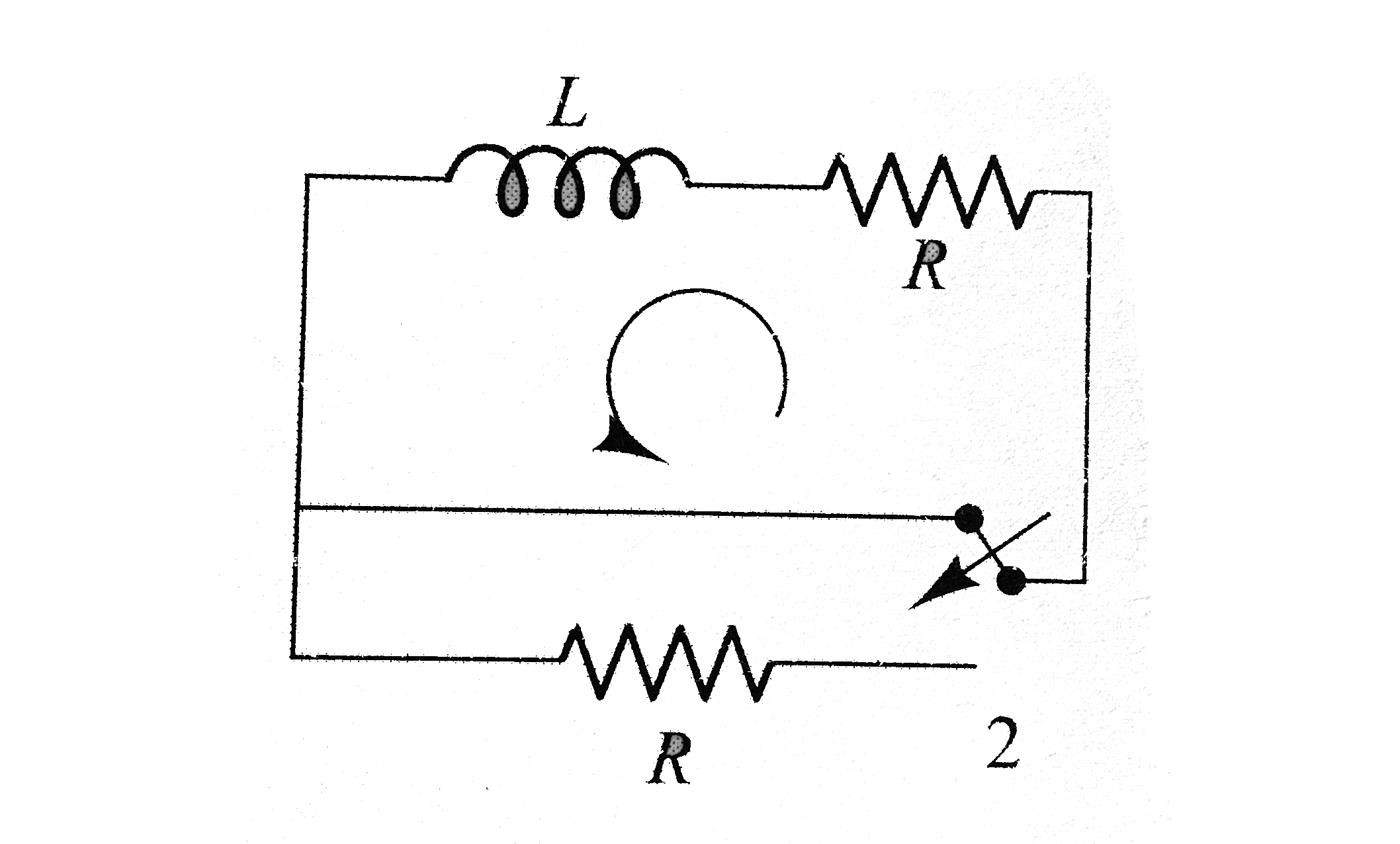
View SolutionIn the circuit shows in Fig. the initail current through the inductor at `t = 0` is `I_(0)`. After a time `t = L//R`, the switch is quickly shifted to position 2.
a. Plot a graph showing the variation of current with time.
b. Calculate the value of current in the inductor at `t = (3)/(2) (L)/(R )`.
View SolutionDuring the decay of current in an `LR` circuit, if the current falls to `eta` times the intial value in time `T`, then determine the value of time constane.
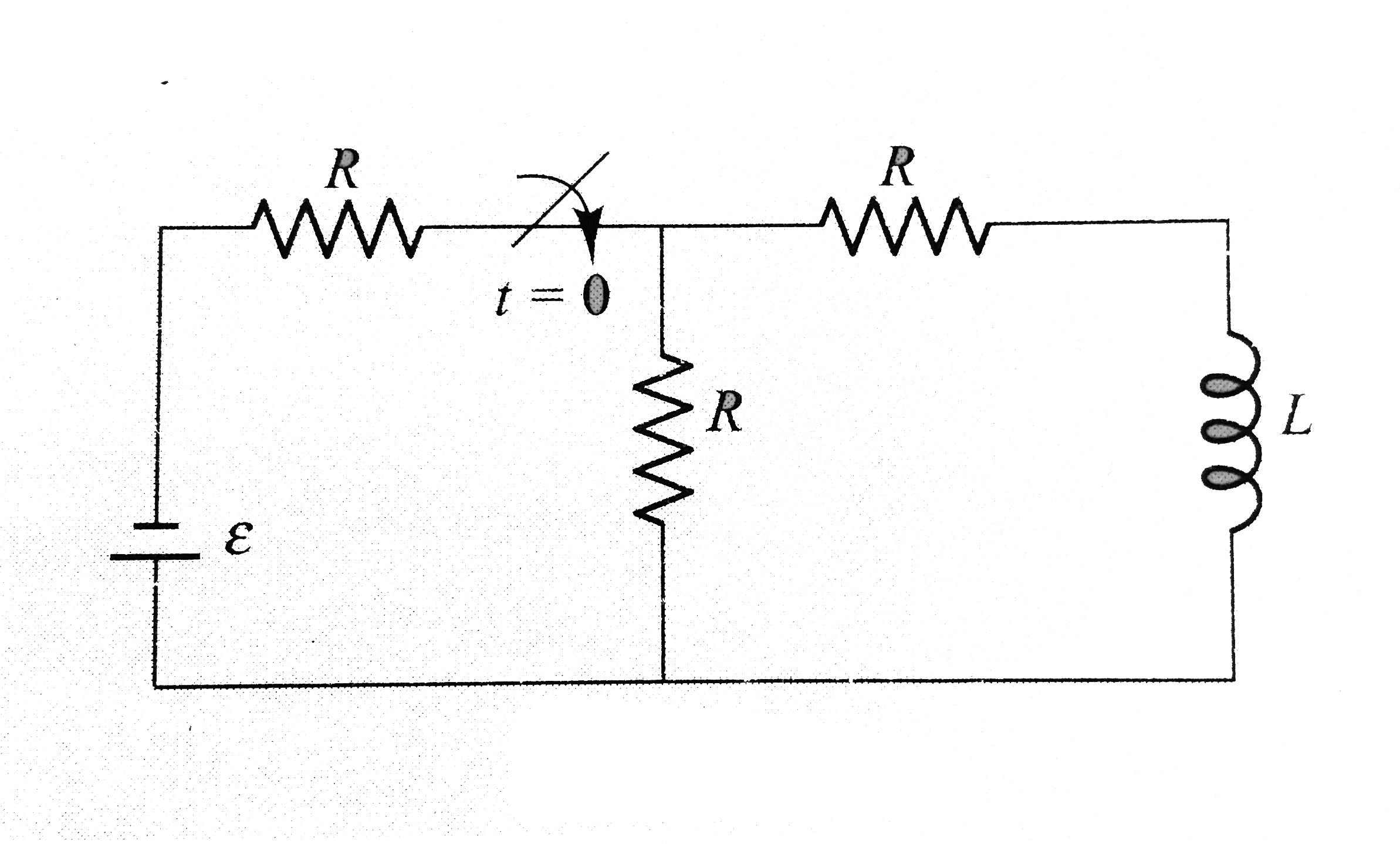
View SolutionIn the following circuit (Fig.)the switch is closed at `t = 0`. Intially, there is no current in inductor. Find out the equation of current in the inductor coil as s function of time.
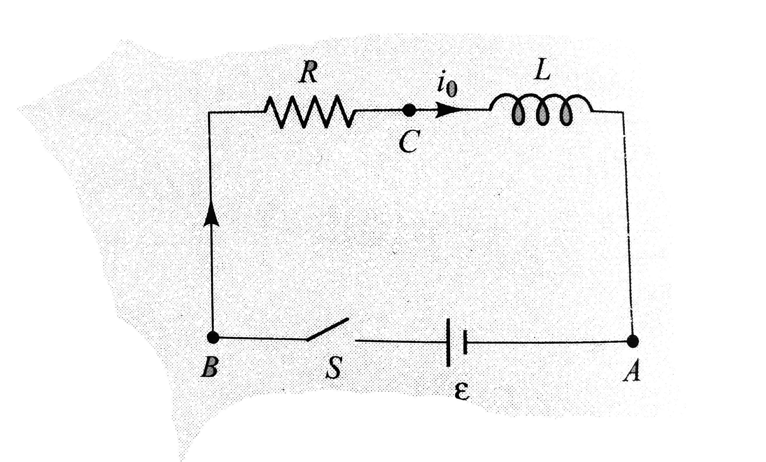
View SolutionFigure shows a circuit consisting of an ideal cell, an inductor `L`, and a resistor `R`, connected in series. Let switch `S` be closed at `t = 0`. Suppose at `t = 0`, the current in the inductor is `i_(o)`, then find out the equation of current as a function of time.
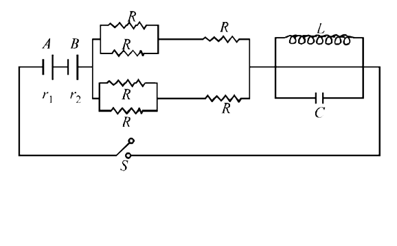
View SolutionIn the figure both cells A and B are of equal emf. Find R for which potential difference across battery A will be zero, long time after the switch is closed. Internal resistance of batteries A and B `(r_1) and (r_2)` respectively`(r_(1)gtr_(2))`.
View SolutionConsider the `RL` circuit in Fig. When the switch is closed in position `1` and opens in position `2`, electrical work must be performed on the inductor and on the resistor. The energy stored in the inductor is for the resistor energy appears as heat.
a. What is the ratio of `P_(L)//P_(R )` of the rate at which energy is stored in the inductor to the rate at which energy is dissipated in the resistor?
b. Express the ratio `P_(L)//P_(R )` as a function of time.
c. If the time constant of circuit is `t`, what is the time at which `P_(L) = P_(R )`?
View SolutionDerive an expression for the total magnetic energy stored in two coils with inductances `L_(1)` and `L_(2)` and mutual inductance `M`, when the currents in the coils are `I_(1)` and `I_(2)`, respectively.
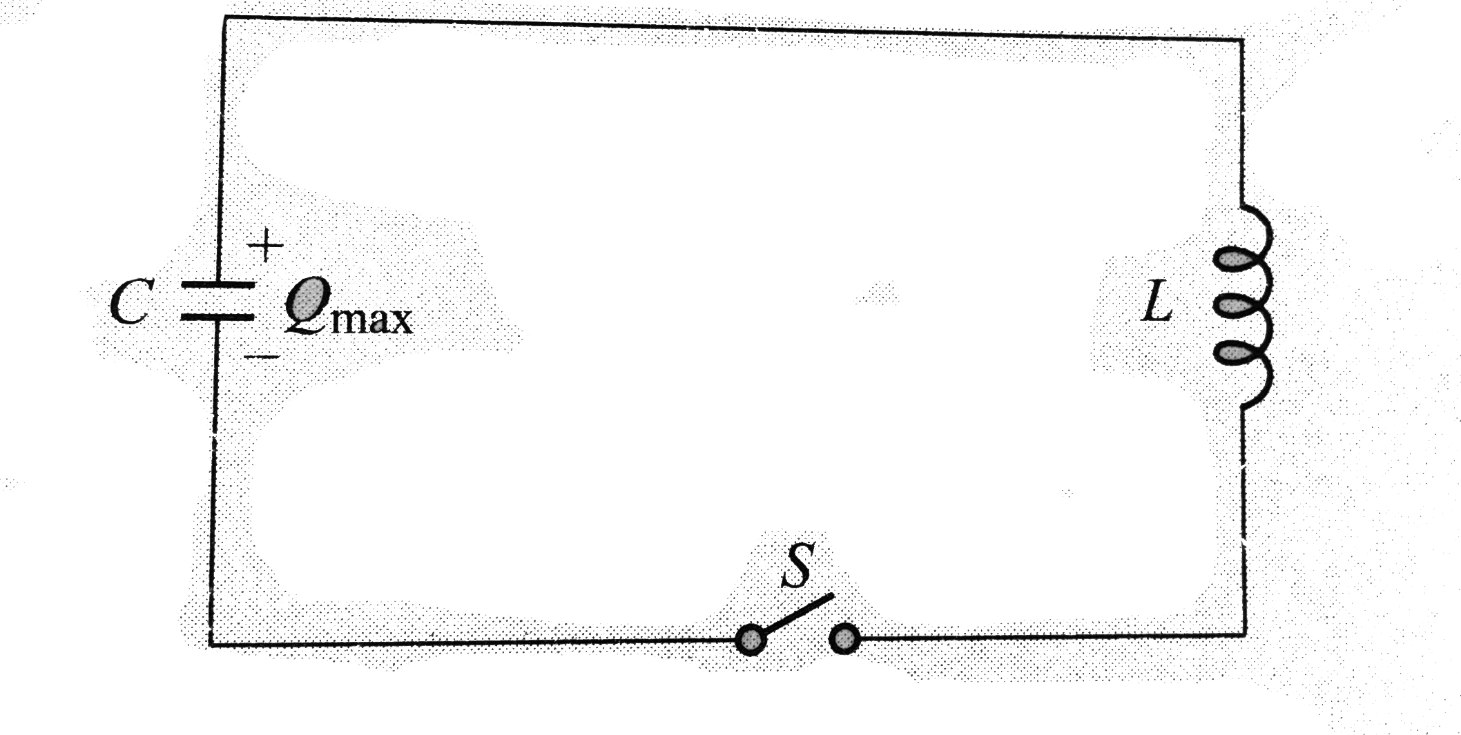
View SolutionIn an `LC` circuit as shows in Fig. the switch is closed at `t = 0`.`Q_(max) = 100 mu C`, `L = 40 mH`, `C = 100 mu F`.
a. Determine the equation for instantaneous change on the capacitor.
b. Determine the equation for instantaneous current in the circuit.
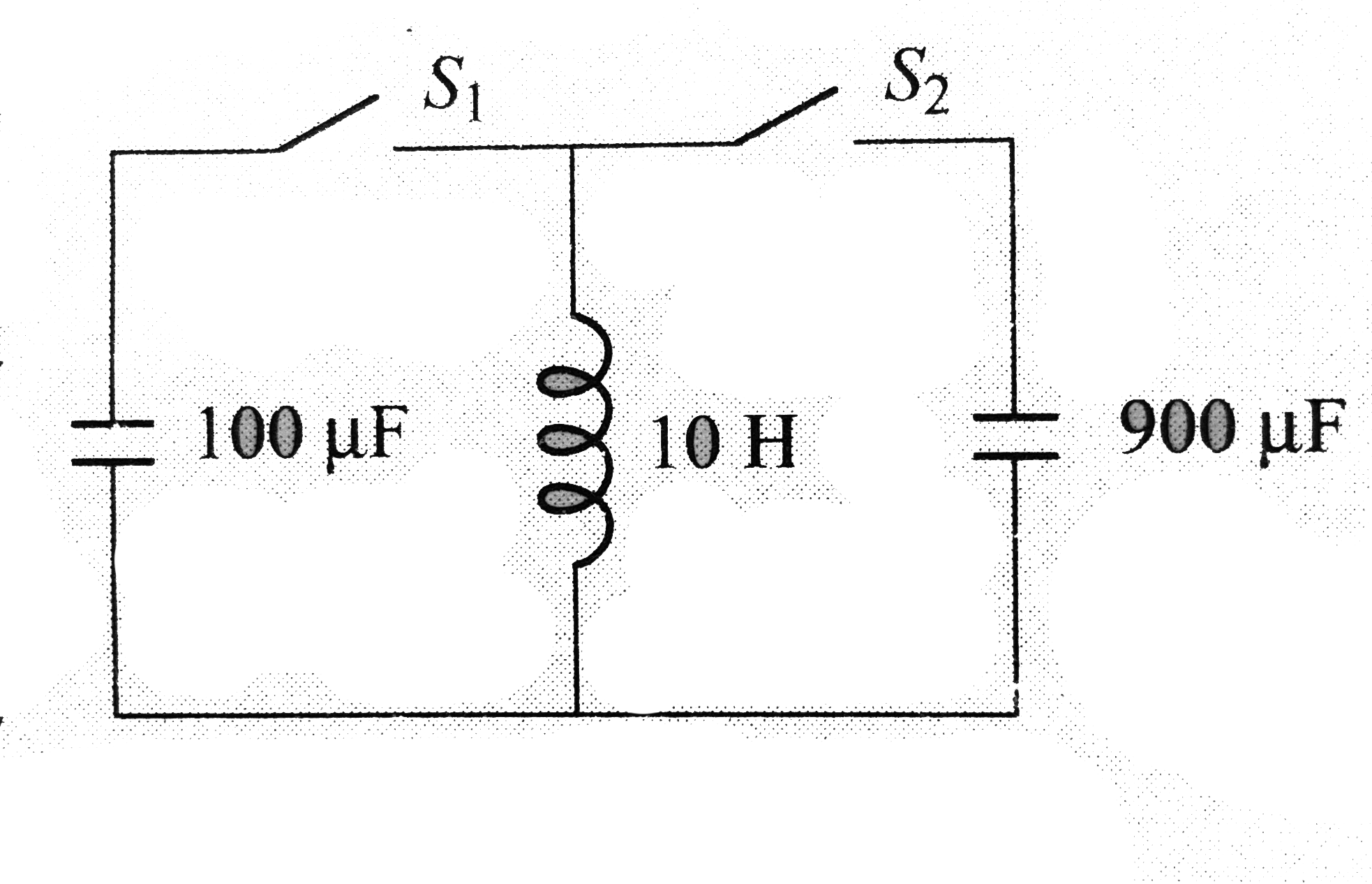
View SolutionInitially the `900 mu F` capacitor is charged to `100 V` and the `100 mu F`capacitor is uncharged in Fig. Then switch `S_(2)` is closed for time `t_(1)`, after which it is opened and at the same instant switch `S_(1)` is closed for time `t_(2)` and then opened. It is now found that `100 mu F` capacitor is charged to `300 mu F` capacitor is charged to `300 V`. Find the minimum possible value of the time interval `t_(1)` and `t_(2)`.
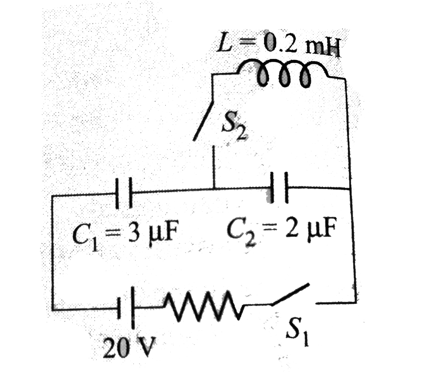
View SolutionThe circuit shows in Fig. is in the steady state with switch `S_(1)` closed. At `t = 0,S_(1)` is opened and switch `S_(2)` is closed.
a. Derive expression for the charge on capacitor `C_(2)` as a function of time.
b. Determine the first instant `t`, when the energy in the inductor becomes one-third of that in the capacitor.
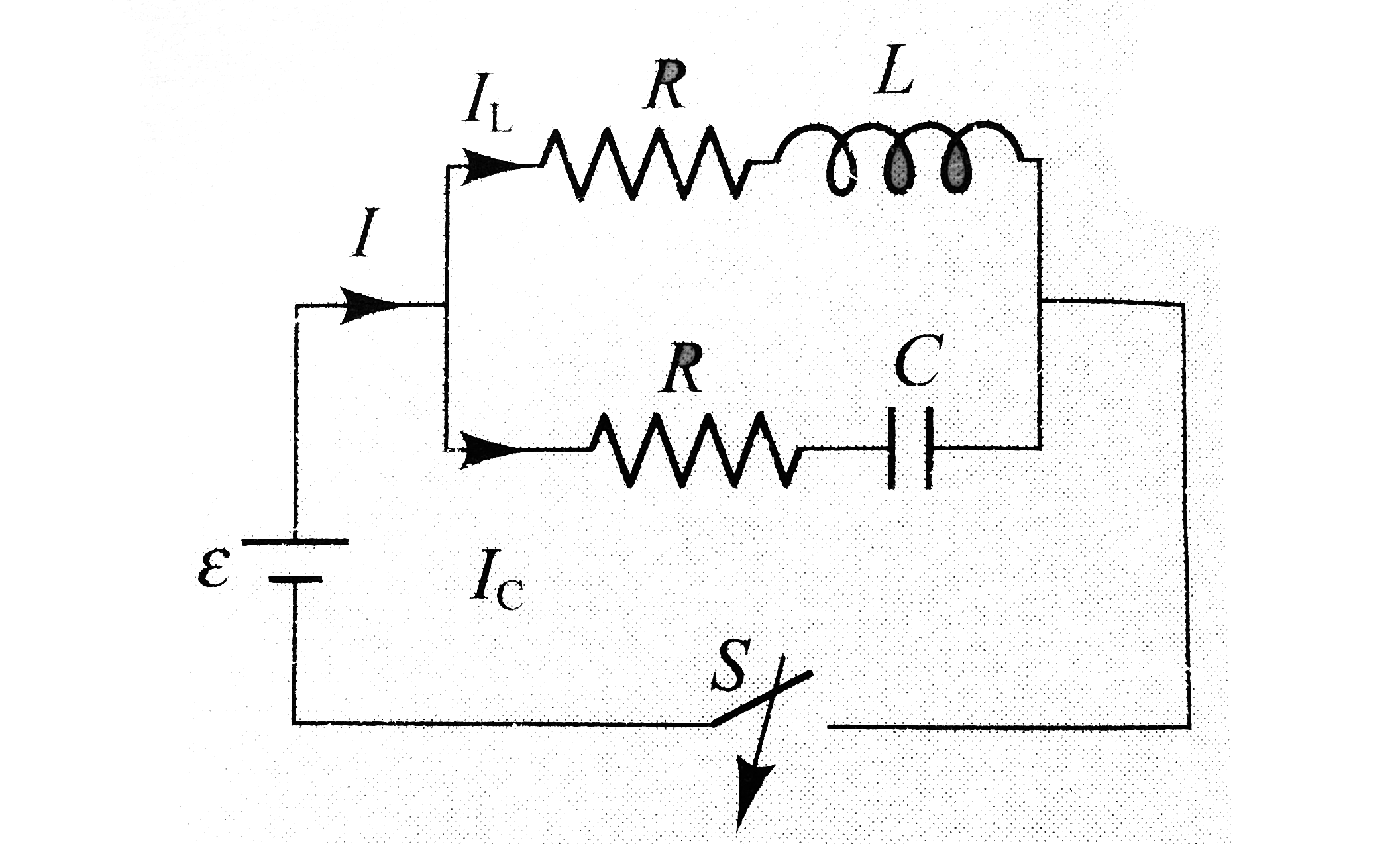
View SolutionIn the circuit shows in Fig. the battery has negligible internal resistance. Show that the current in the circuit through the battery rises instanlty to its steady state value `E//R` when the switch is closed, provided that resistance `R` is `sqrt(L//C)`.
View SolutionAn inductor of inductance `2.0mH` is connected across a charged capacitor of capacitance `5.0muF` and the resulting `L-C` circuit is set oscillating at its natural frequency. Let `Q` denotes the instantaeus charge on the capacitor and `I` the current in the circuit. It is found that the maximum value of `Q` is `200muC`.
View Solution
Illustration questions and complete solutions for chapter INDUCTANCE of CENGAGE PHYSICS (ENGLISH) of Class 12
All Exercises from CENGAGE PHYSICS Class 12 PHYSICS INDUCTANCE
- Archives (fills In The Blanks)
- Archives (integer)
- Archives (linked Compreshension)
- Archives (multiple Correct)
- Archives (single Correct )
- Comprehension Type
- Concept Based
- Exercise 4.1
- Exercises (assertion-reasoning)
- Exercises (integer)
- Exercises (linked Compreshension)
- Exercises (multiple Correct )
- Exercises (single Correct )
- Exercises (subjective)
- Illustration
- Multiple Correct Answer
- Single correct Answer Type
- Solved Examples
- Subective Type