Complete Solutions to Check point 2.5 of chapter ELECTROSTATIC POTENTIAL AND CAPACITORS of Class 12 book with complete answers and questions
| Class 12 | PHYSICS |
| Chapter | ELECTROSTATIC POTENTIAL AND CAPACITORS |
| DC PANDEY NEET | Check point 2.5 |
| Number Of Questions | 20 |
| Academic Year | 2023-24 |
Three capacitors each of capacitance `C` and of breakdown voltage `V` are joined in series. The capacitance and breakdown voltage of the combination will be
View SolutionIn given circuit when switch S has been closed, then charge on capacitor A and B respectively

View SolutionThree condensers each of capacitance 2F are put in series. The resultant capacitance is
View SolutionTwo capacitors of capacitance `2 muF` and `3 muF` are joined in series. Outer plate of first capacitor is at `1000` volt and outer plate of second capacitor is earthed (grounded). Now the potential on inner plate of each capacitor will be
View SolutionA series combination of three capacitors of capacities `1 muF, 2muF` and `8 muF` is connected to a battery of e.m.f. `13 volt`. The potential difference across the plates of `2 muF` capacitor will be
View SolutionA parallel plate capacitor is made by stacking n equally spaced plates connected alternatively. If the capacitance between any two adjacent plates is 'C' then the resultant capacitance is
View SolutionFour capacitors of equal capacitance have an equivalent capacitance `C_(1)` when connected in series and an equivalent capacitance `C_(2)` when connected in parallel. The ratio `(C_(1))/(C_(2))` is
View SolutionThree capacitors of capacitance `3 muF` are connected in a circuit. Then, their maximum and minimum capacitance will be
View SolutionThree capacitors each of capacity `4 muF` are to be connected in such a way that the effective capacitance is `6 muF`. This can be done by
View SolutionIn the figure shown, the effective capacitance between the points `A` and `B`, if each has capacitance `C`, is
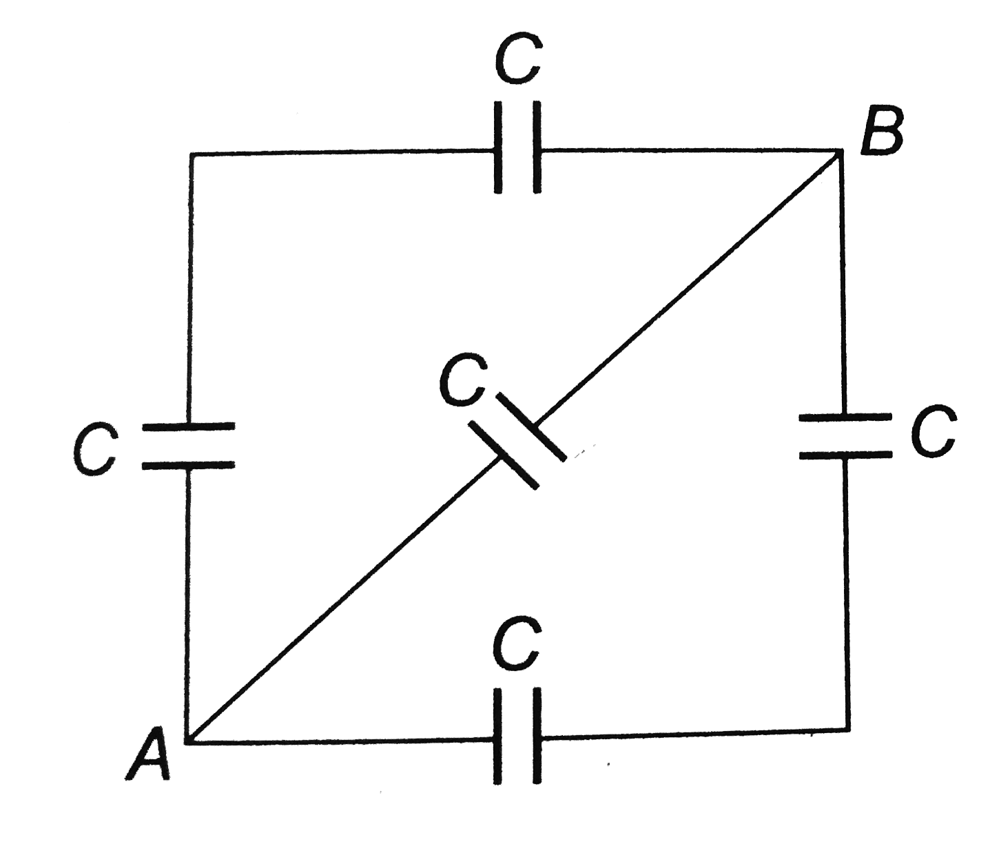
View SolutionFour equal capacitors, each of capacity `C`, are arranged as shown. The effective capacitance between `A` and `B` is
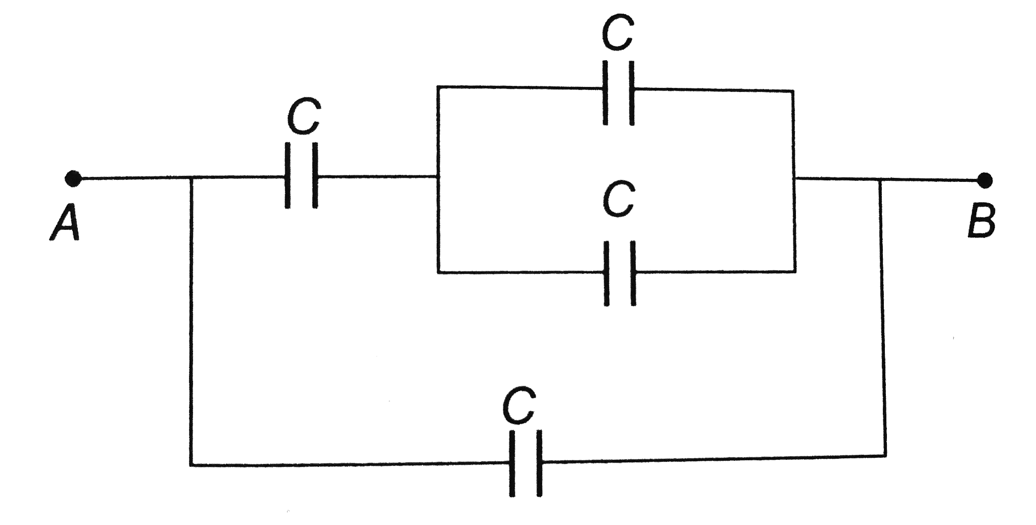
View SolutionIn the circuit as shown in the figure the effective capacitance between `A` and `B` is
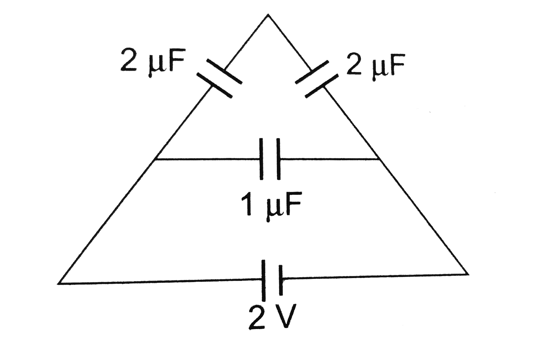
View SolutionThe charge on any of the `2 muF` capacitors and `1 muF` capacitor will be given respectively (in `muC`) as
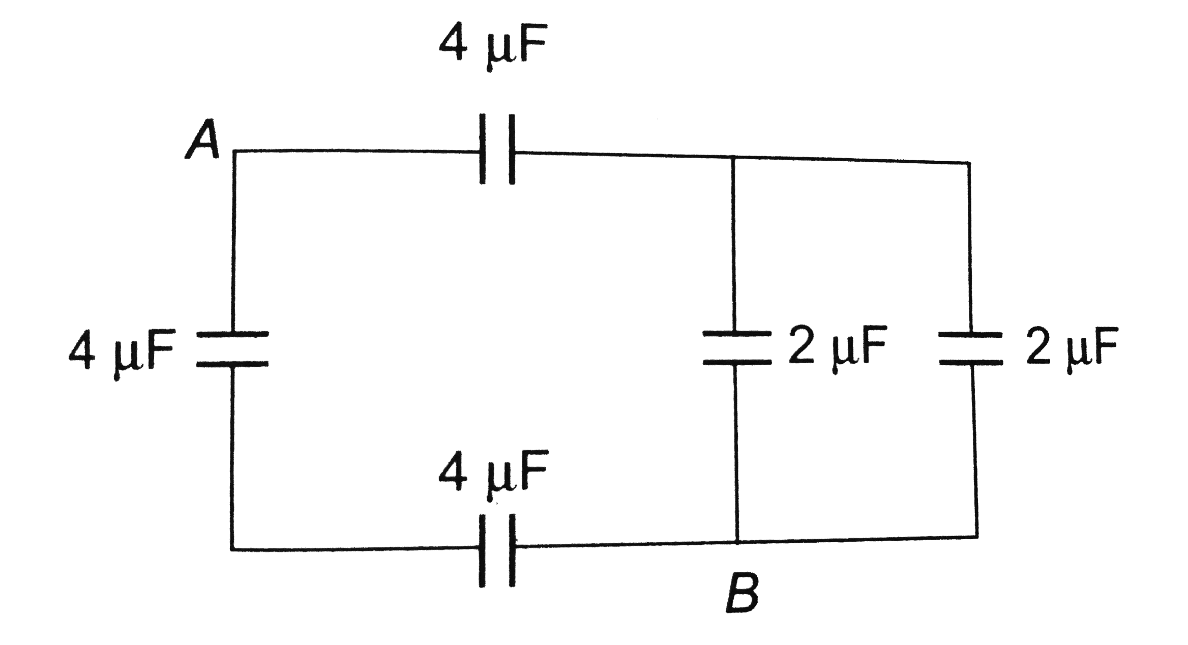
View SolutionEquivalent capacitance between `A` and `B` is
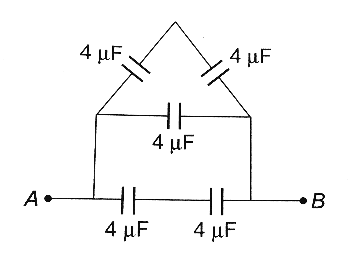
View SolutionThe energy stored in a capacitor of capacitance `100 muF` is 50 J. Its potential difference is
View SolutionThe potential energy of a charged parallel plate capacitor is `U_(0)`. If a slab of dielectric constant `K` is inserted between the plates, then the new potential energy will be
View SolutionA series combination of `n_(1)` capacitors, each of value `C_(1)`, is charged by a source of potential difference `4 V`. When another parallel combination of `n_(2)` capacitors, each of value `C_(2)`, is charged by a source of potential difference `V`, it has same (total) energy stored in it, as the first combination has. the value of `C_(2)`, in terms of `C_(1)`, is then
View SolutionIf the charge on a capacitor is increased by 2C, then the energy stored in it increases by 21 %. The original charge on the capacitor is
View SolutionA capacitor of capacitance value `1 muF` is charged to 30 V and the battery is then disconnected. If it is connected across a `2 muF` capacotor, then the energy lost by the system is
View SolutionA parallel plate capacitor is charged to a potential difference of 50 volts. It is then discharged through a resistance for 2 seconds and its potential drops by 10 volts. Calculate the fraction of energy stored in the capacitance.
View Solution
Check point 2.5 questions and complete solutions for chapter ELECTROSTATIC POTENTIAL AND CAPACITORS of DC PANDEY PHYSICS (HINGLISH) of Class 12