Complete Solutions to ILLUSTRATION_TYPE of chapter CAPACITANCE of Class 12 book with complete answers and questions
| Class 12 | PHYSICS |
| Chapter | CAPACITANCE |
| PHYSICS GALAXY | ILLUSTRATION_TYPE |
| Number Of Questions | 45 |
| Academic Year | 2023-24 |
There are two conductors of capacitance `C` and `2C` are charged equally with charge `+Q` each and connected with a thin conducting wire and a switch as shown in figure. Find the final charges on the conductors after closing the switch.
 03:54View Solution
Two isolated metallic solid spheres of radii R and 2R are charged such that both of these have same charge density `sigma`. The spheres are located far away from each other and connected by a thin conducting wire. Find the new charge density on the bigger sphere.
07:16View SolutionA radioavtive source in the form of a metal sphere of daimeter `10^(-3)` m emits `beta`-particles at a constant rate of `6.25 xx 10^(10)` particles per second. If the source is electrically insulated, how long will it take for its potential to rise by `1.0 V`, assuming that `80%` of the emitted `beta`-particles escape the socurce?
04:45View SolutionA capacitor is formed of two concentric spherical conducting shells ofradii `a` and `b`. If the medium between the spherical shells has a dielectric constant `K_(1)` from radius `a` to `r` and `K_(2)` from radius `r` to `b`, find the capacitance of such a spherical capacitor shown in figure.
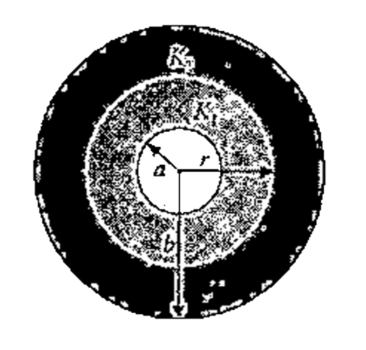 06:10View Solution
A parallel plate capacitor ils arrranged horizontally in a mechanical situation with the lower plate is fixed and the other connected with a perpendicular spring as shown in figure. The area of eachh plate is `A` and in equilibrium the distance between te plates is `d_(0)`. WHen the capacitor is connected with a source of voltage `V`, a new equilibrium appears after some displacement in upper plate with the new distasnce between the plates `d_(1)`. Given that mass of the upper plate is `m`
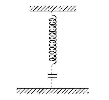 03:48View Solution
The lower plate of a parallel plate capacitor is fixed on an insulating plane as shown in figure. The upper plate is suspended from one end of a balance. Initially the capacitor is uncharged and balance is in equilibrium state. A voltage `V` is applied between the plates, what additional weight should be placed to maintain the balance? Consider the separation between the plates to be d and the area of each plate is `A`.
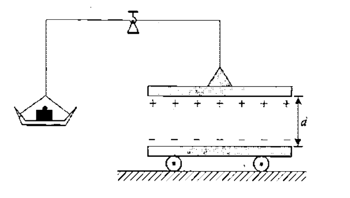 01:57View Solution
A capacitor of `10muF` capacitance is having `50 muC` charge. Find amount of heat produced when this capacitor is connected across a `10V` battery as shown in figure and switch is closed.
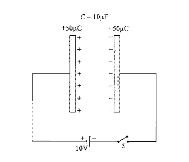 03:19View Solution
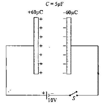
A capacitor of `5muF` capacitance is charged with an initial charge `60muC` as shown in figure and connected across a `10V`battery. Find the amount of heat produced when switch is closed.
 02:50View Solution
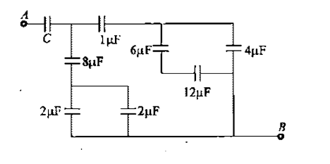
Find the capacitance `C` in the circuit shown in figure if the equivalent capacitance between points `A` and `B` is `1muF`.
 07:28View Solution
Two capacitors of capacitances `C_(1)=2muF` and `C_(2)=8muF` are connected in series and the resulting combination is connected across a `300V` battery. Calculate the charge, potential difference and energy stored in the capacitor separately.
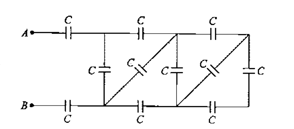
05:25View SolutionFind the equivalent capacitance of given network of capacitors between `A` and `B`. Each capacitor has capacitance
 09:17View Solution
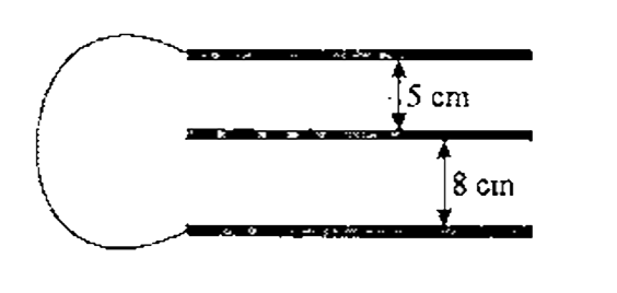
Three conducting plates are placed parallel to one another as shown in the figure. The outer plates are neutral and connected by a conducting wire. The inner plate is isolated and carries a total charge amounting to `10muC`. The charge densities on upper. and lower face of middle plate are `sigma_(1)` and `sigma_(2)`. Find `5sigma_(1)//sigma_(2)`
 05:12View Solution
Figure shows four parallel plates kept at equal separation forming three parallel plate capacitors. The capacitance between two adjoining plates is `C`. Find out equivalent capacitance between `A` and `B`.
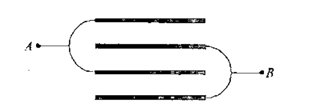 04:26View Solution
Two circular plates `A` and `B` of a parallel plate air capacitor have a diameter of `0.1m` and are `2xx10^(-3) m` apart. The plates `C` and `D`, of a similar capacitor have a diameter of `0.12m` and are `3xx10^(-3)m` apart. Plate `A` is earthed and plates `B` and `D` are connected together as shown in figure. Plate `C` is connected to the positive pole of a `120V` battery whose negative terminal is earthed. Calculate.
(a) the combined capacitance of the arrangement and
(b) the energy stored in it.
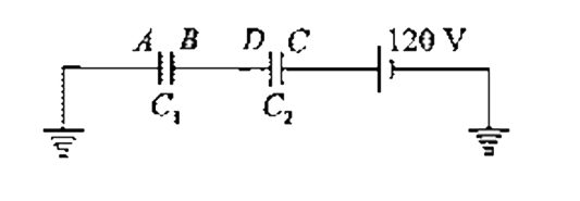 08:47View Solution
Find the potential difference between points `M` and `N` of the circuit shown in figure. The battery voltage is equal to `xi` and the capacitance ratio `C_(2)//C_(1)` is equal to `eta`
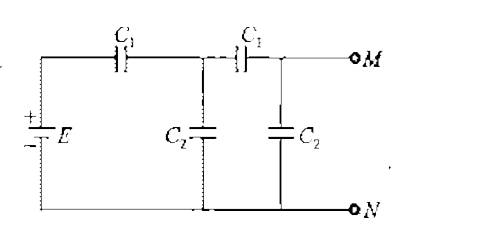 08:09View Solution
In the circuit shown in figure four capacitors are connected to a battery. Determine the potential difference `V_(M)-V_(N)` between· points `M` and `N` of the circuit. Find the conditions under which it is equal to zero.
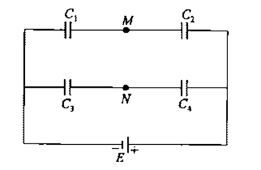 03:49View Solution
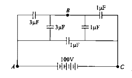
In circuit shown in figure calculate the potential difference between the points `A` and `B` and between the points `B` and `C` in the steady state.
 03:42View Solution
Find the equivalent capacitance of the infinite ladder shown in figure between the points `A` & `B`.
 04:48View Solution
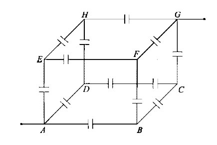
Figure shows a circuit of 12 capacitors each of capacitance `C` connected along the edges of a cubical wireframe as shown. Find the equivalent capacitance between terminals `A` & `G`.
 04:37View Solution
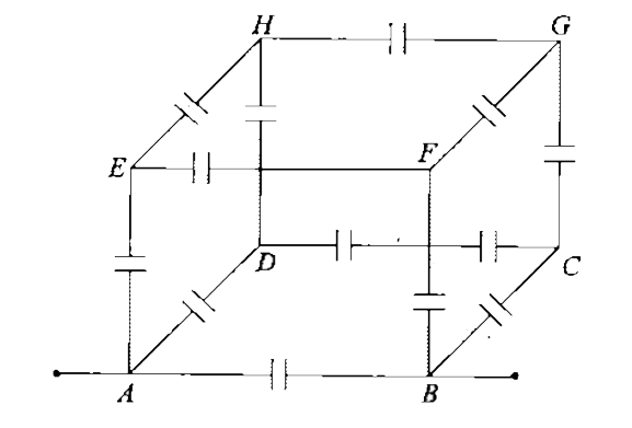
Figure shows a circuit of 12 capacitors each of capacitance `1C` connected along the edges of a cubical wireframe as shown. Find the equivalent capacitance between terminals `A` & `B`.
 05:32View Solution
Determine the potential at point `1` of the circuit shown in Fig., assuming the potential at the point `O` to be equal to zero.
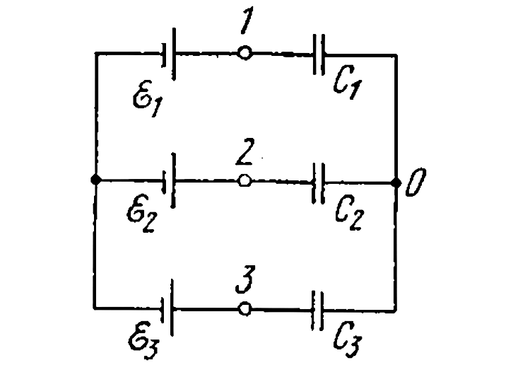
using the symmetry of the formula obtained, write the expressions for the potentials at points 2 and 3.06:34View SolutionA `muF` capacitor `C_1` is charged to `V_0 = 120 V`. The charging battery is then removed and the capacitor is connected in parallel to an uncharged `+ 4muF` capacitor `C_2`.
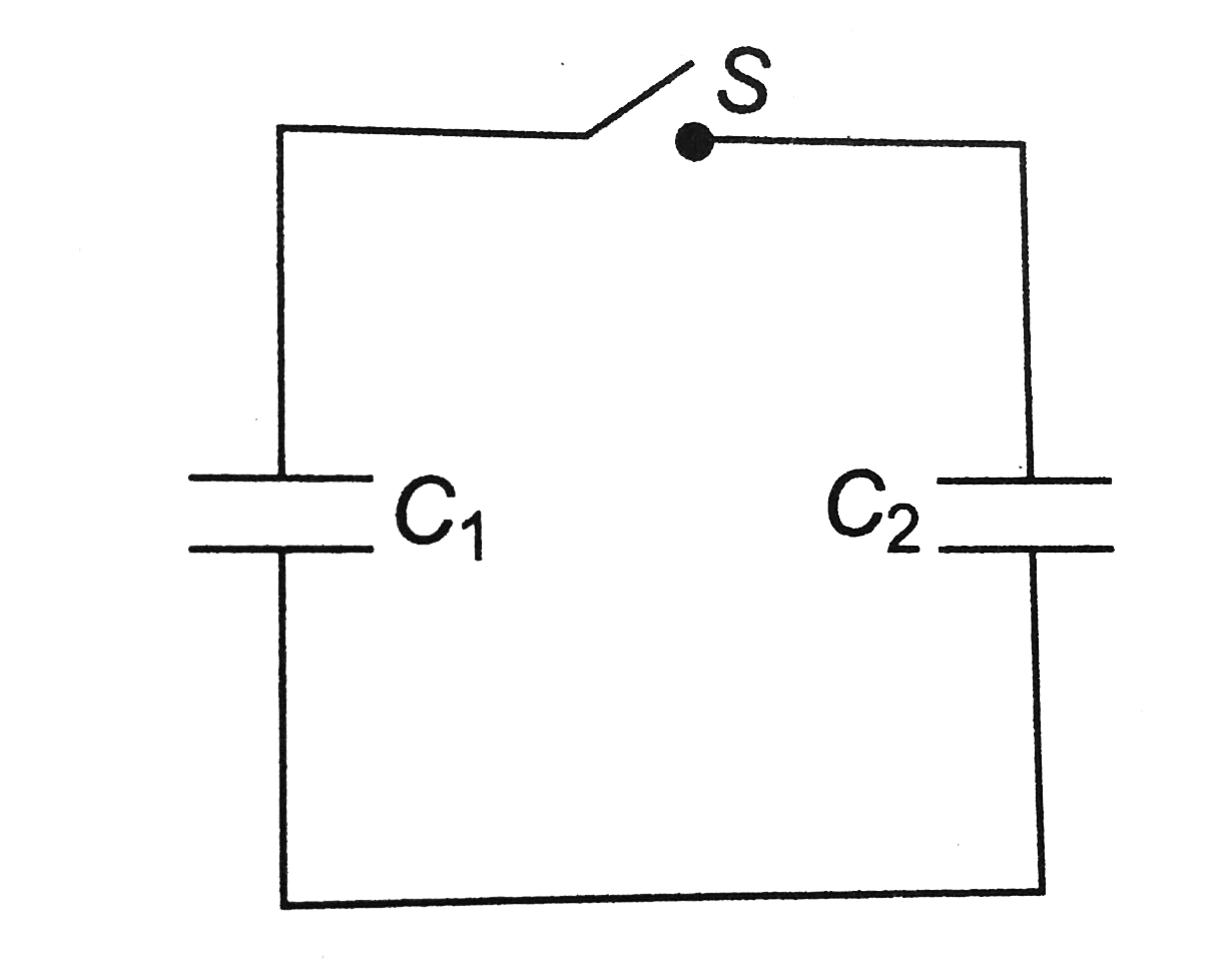
(a) what is the potential difference `V` across the combination?
(b) what is the stored energy before and after the switch `S` is closed?02:43View SolutionIn the circuit shown in figure find the charges on the three capacitors in steady state.
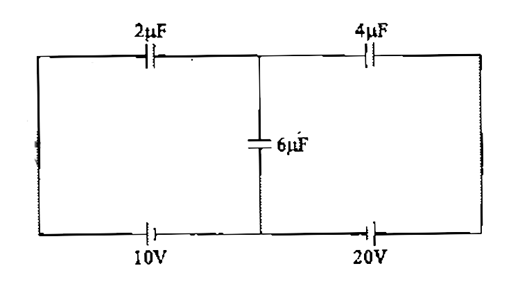 03:28View Solution
A capacitor has capacitance `10muF` audit is charged to a potential `150V`. A second capacitor has a capacitance of `20 muF` and it is charged to a potential of `300V`. After charging, the two capacitors are connected in parallel with their same polarity plates together by using wires of negligible capacitance. Find how much energy is dissipated?
05:03View SolutionFigure shows four capacitors with capacities `C, 2C, 3C` and `4C` are charged to the voltage, `V, 2V, 3V` and `4V` correspondingly. The circuit is closed by closing all the switches. Find the potential difference across all capacitors in steady state.
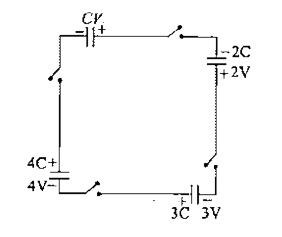 05:56View Solution
A battery of `10V` is connected to a capacitor of capacity `0. lF`. The battery is now removed and this capacitor is connected to a second uncharged capacitor. If the charges are distributed equally on these two capacitors, find the total energy stored in the two capacitors. Find the ratio of final energy to initial energy stored in capacitors.
03:23View SolutionTwo capacitors `A` and `B` with capacities `3muF` and `2muF` are charged to a potential difference of `100 V` and `180V`, respectively. The plates of the capacitors are connected as show in figure with one wire of each capacitor free. The upper plate of `A` is positive and that of `B` is negastive. An uncharged `2muF` capcitor `C` with lead wires falls on the free ends to complete the circuit. Calculate
a. the final charge on the three capacitors.
b. the amount of electrostatic energy stored in the system before and after completion of the circuit.
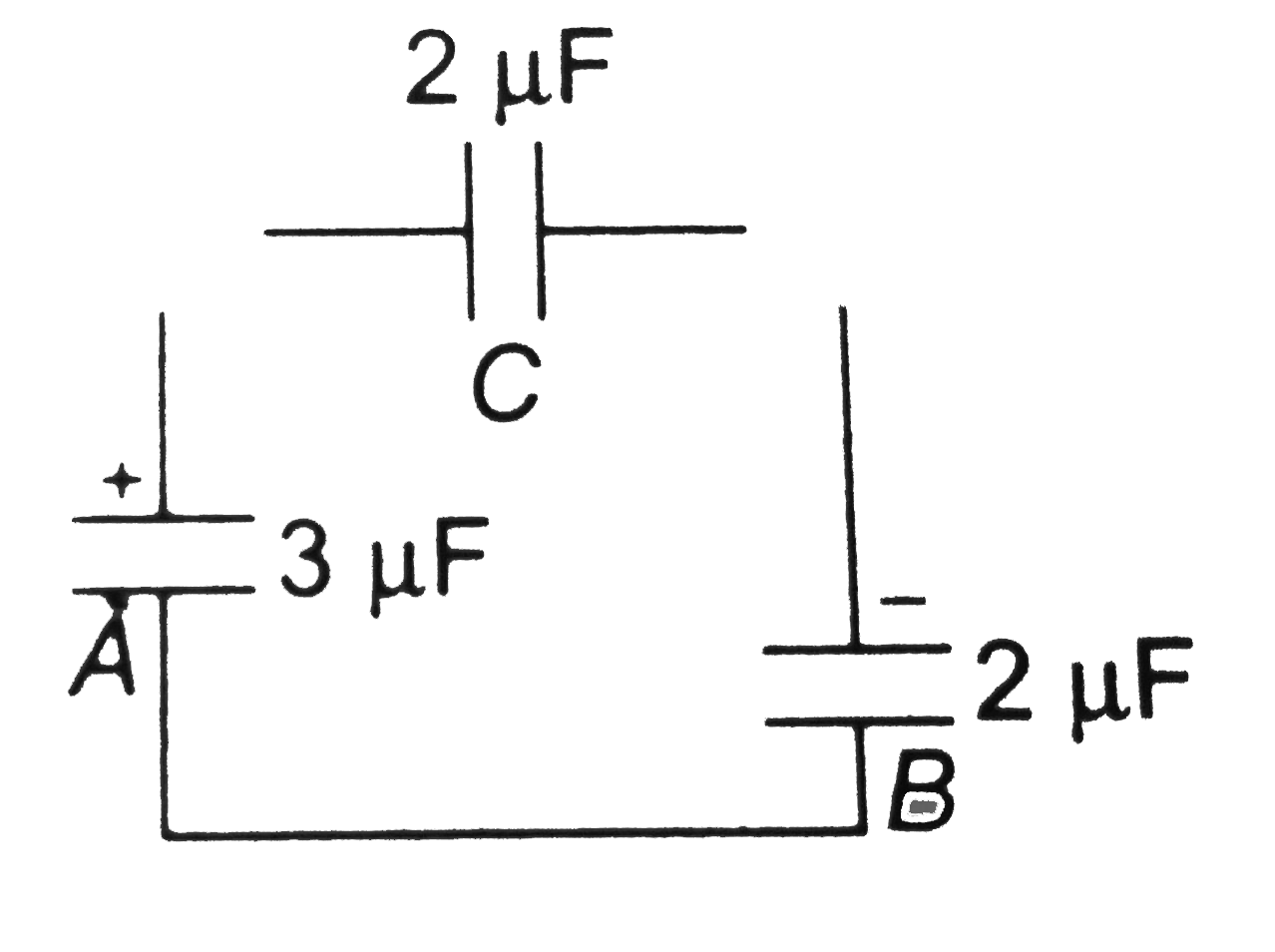 08:11View Solution
What charges will flow after the shorting of the swich `Sw` in the circuit illustrated in Fig through sections 1 and 2 in the directions indicated by the arrown?
 05:13View Solution
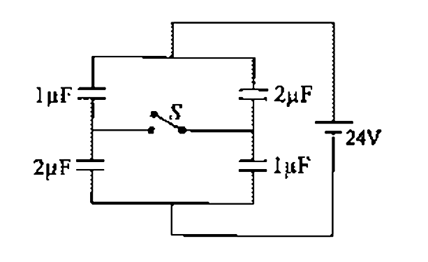
Four uncharged capacitors are charged by `24V` battery as shown in the figure. How much charge flows through switch `S` when it is closed?
 03:41View Solution
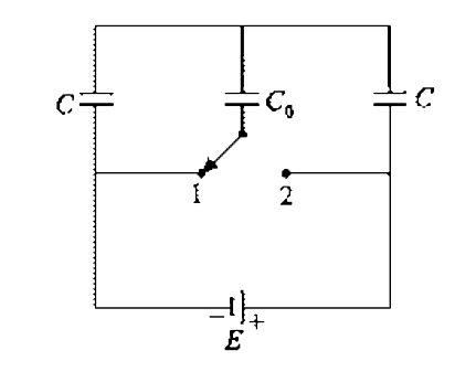
Figure shows a circuit with three capacitors connected with a battery. What amount of heat will be generated in the circuit when the switch `S` is shifted from position 1 to 2.
 03:36View Solution
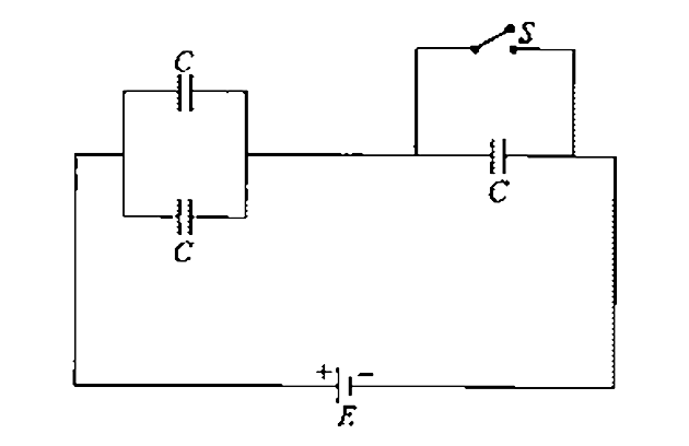
In the circuit shown, each capacitor has a capacitance `C`, The cell voltage is `E`, Find the amount of charge flowing through the switch when it is closed and also find the heat dissipated in the circuit when the switch is closed.
 05:09View Solution
Find the capacitance between A and B if three dielectric slabs of dielectric constants `K_(1) area `A _(2)` and thickness `d_(2)`) are inserted between the plates of a parallel late capacitor of plate area A. (Given that the distance between the two plates is `d_(1)=d_(2)+d_(2)`.)
 .03:29View Solution
A parallel plate capacitor is maintained at a certain potentail difference. When a 3mm thick slab is intorduced between the plate, in a order to maintain the same potential difference, the distance between the plates is increased by 2.4 mm. Find the dielectric constant of the slab.
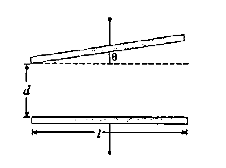
02:37View SolutionFigure shows a parallel plate capacitor with its plate area `A=lb` and plate separation `d` at left end of the plates. Upper plate of capacitor is slightly tilted by a very small angle 8 as shown. Find the capacitance of this capacitor.
 04:23View Solution
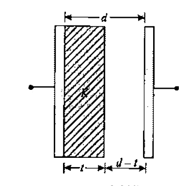
A parallel plate capacitor consists of two metal plates of area `A` and separation `d`. A slab of thickness `t` and electric constant `K` is inserted between the plates with its faces parallel to the plates and having the same surface area as that of the plates. Find the capacitance of the system.
IF `K=2`, for what value of `t//d` will the capacitance of the system be `3//2` times that of the air capacitor? Calculate the energy in the two cases and account for the energy change.
 05:16View Solution
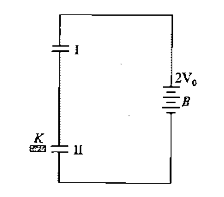
Two identical capacitors are connected as shown in fignre. A dielectric slab is introduced between the plates of one of the capacitors so as to fill the gap, the battery remaining connected. What will be the capacitance, the charge, potential difference and stored energy for each capacitor?
 04:23View Solution
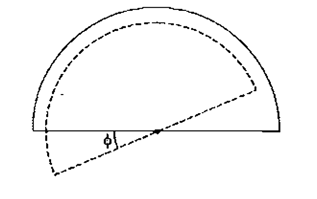
A capacitor consists of two stationary plates shaped as a semi-circle of radius `R` and a movable plate made of dielectric with permittivity `K` and capable ofrotating about an axis `O` between the stationary plates. The thickness of movable plate is equal to `d` which is practically the separation between the stationary plates. A potential difference `V` is applied to the capacitor. Find the magnitude of the moment of forces relative to the axis `O` acting on the movable plate in the position shown in figure.
 06:44View Solution
The distance between the parallel plates of a charged condenser is `d= 5cm` and the intensity of the field `e = 300V//cm`. A slab of dielectric constant `k= 5` and `1 cm` wide is inserted parallel to the plates. Determine the potential difference between the plates before and after the slab is inserted. If the slab is replaced by a metal plates so that the final potential difference remains unchanged, what be the thickness ofthe plate?
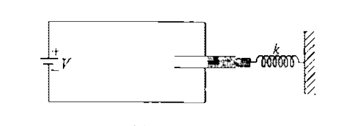
07:55View SolutionIn the arrangement shown in figure a. dielectric slab of dielectric constant `K` is partially inside a parallel plate capacitor. Assuming gravity to be absent, calculate the extension in the spring if the whole system is in equilibrium. If the slab is slightly displaced will it perform SHM? If the liattery is disconnected and then the slab is slightly displaced, will it perform SHM?
Given that `I` is the length of the plates, ``b is the breadth of plates and dis the separation between the plates.
 04:24View Solution
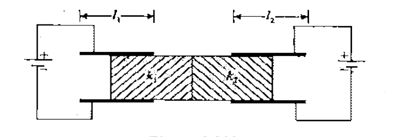
Figure shows two parallel plate capacitors with fixed plates and connected to two batteries. The separation between the plates is the same for the two capacitors. The plates are rectangular in shape with width `b` and length `l_(1)` and `l_(2)`. The left half of the dielectric slab has a dielectric constant `k_(1)` and the right half `k_(2)` Neglecting any friction, find the ratio of the voltage of ihe left battery for that of the right battery for which the dielectric. slab mayremain in equilibrium.
 02:23View Solution
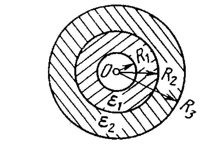
There is a double-layer cylindrical capacitor whose parameters are shoen in Fig. The breakdown field strength values for these dielectrics are equal to `E_(1)` and `E_(2)` respectively. What is the breakdown voltage of this capacitor if `epsilon_(1) R_(1) E_(1) lt epsilon_(2) R_(2) E_(2)` ?
 07:25View Solution
Between the plates of a parallel-plate capacitor there is a metallic plate whose thickness takes up `eta=0.60` of the capacitor gap. When that plate is absent the capacitor has a capacity `C=20nF`. The capacitor is connected to a constant voltage source. `V = 1 00V`. The metallic plate is slowly extracted from the gap. Find the mechanical work performed in the process of plate extraction.
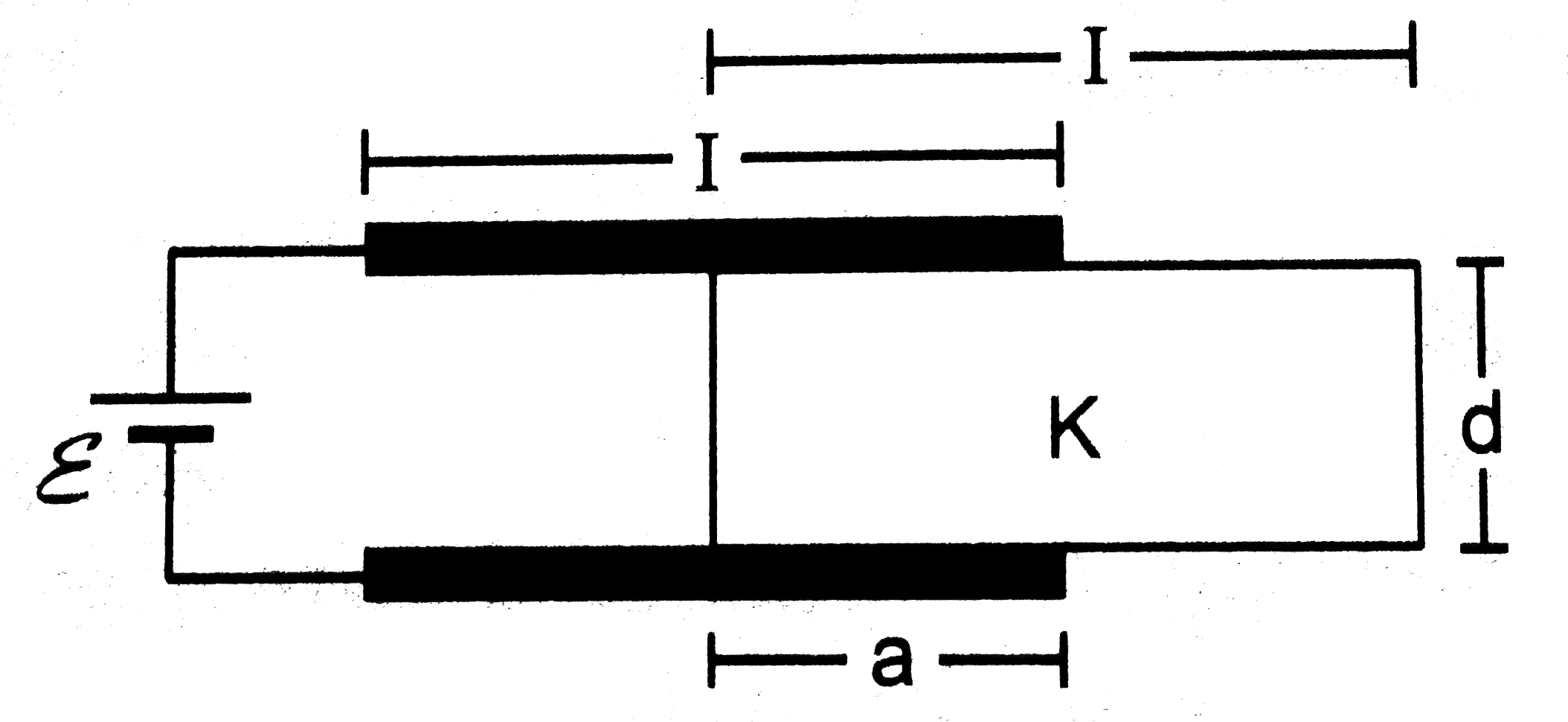
05:38View SolutionConsider the situation shown in figure .The plates of the capacitor have plate area `A` and are clamped in the laboratory . The dielectric slab is released from rest with a length a inside the capacitor. Neglecting any effect of friction or gravity, show that slab will execute periodic motion and find its time period.

 13:00View Solution
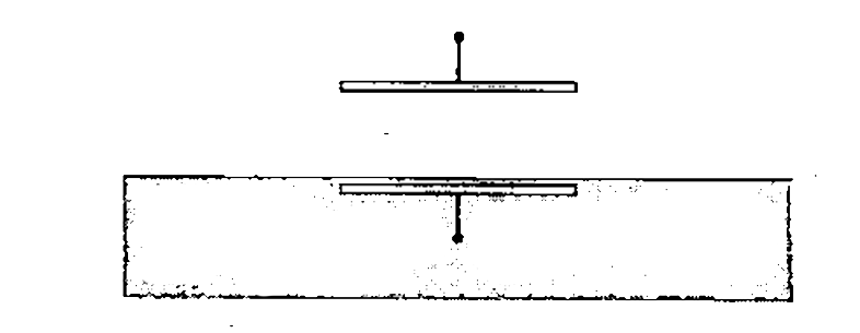
Figure shows a horizontal parallel plate capacitor is lowered on a liquid surface in such a way that its lower plate is just submerged in the liquid of dielectric constant `k`. Find the height to which the liquid level will be raised between the plates if the capacitor plates are given a surface charge density `+sigma` and` -sigma` on its plates.
 04:43View Solution
A parallel plate capacitor is made by fixing two plates inside of a container as shown in figure. The plates are connected to a battery of voltage `V`. If at `t=0` the tap is opened from which a liquid of dielectric constant `k` starts filling in the container at a constant rate of `rm^(3)//s`, find the current in connecting wires as a function of time. Neglect any resistance in connecting wires.
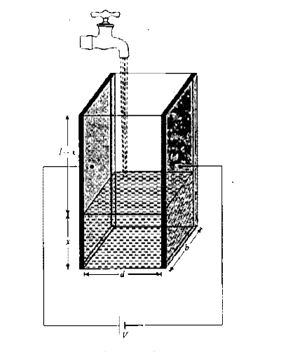 05:19View Solution
ILLUSTRATION_TYPE questions and complete solutions for chapter CAPACITANCE of GK PUBLICATIONS PHYSICS (HINGLISH) of Class 12
