Complete Solutions to NUMERICAL MCQS of chapter CAPACITANCE of Class 12 book with complete answers and questions
| Class 12 | PHYSICS |
| Chapter | CAPACITANCE |
| PHYSICS GALAXY | NUMERICAL MCQS |
| Number Of Questions | 56 |
| Academic Year | 2023-24 |
Two capacitors `3muF` and `6muF` are connected in series across a potential difference of `120V`. Then the potential difference across `3muF` capacitor is:
View SolutionInitial charges (with proper sign) on the plates of two identical capacitors, each of `1muF`, are as shown. When both `S_(1)` and `S_(2)` are closed, the potential difference between `A` and `B` will finally.become :

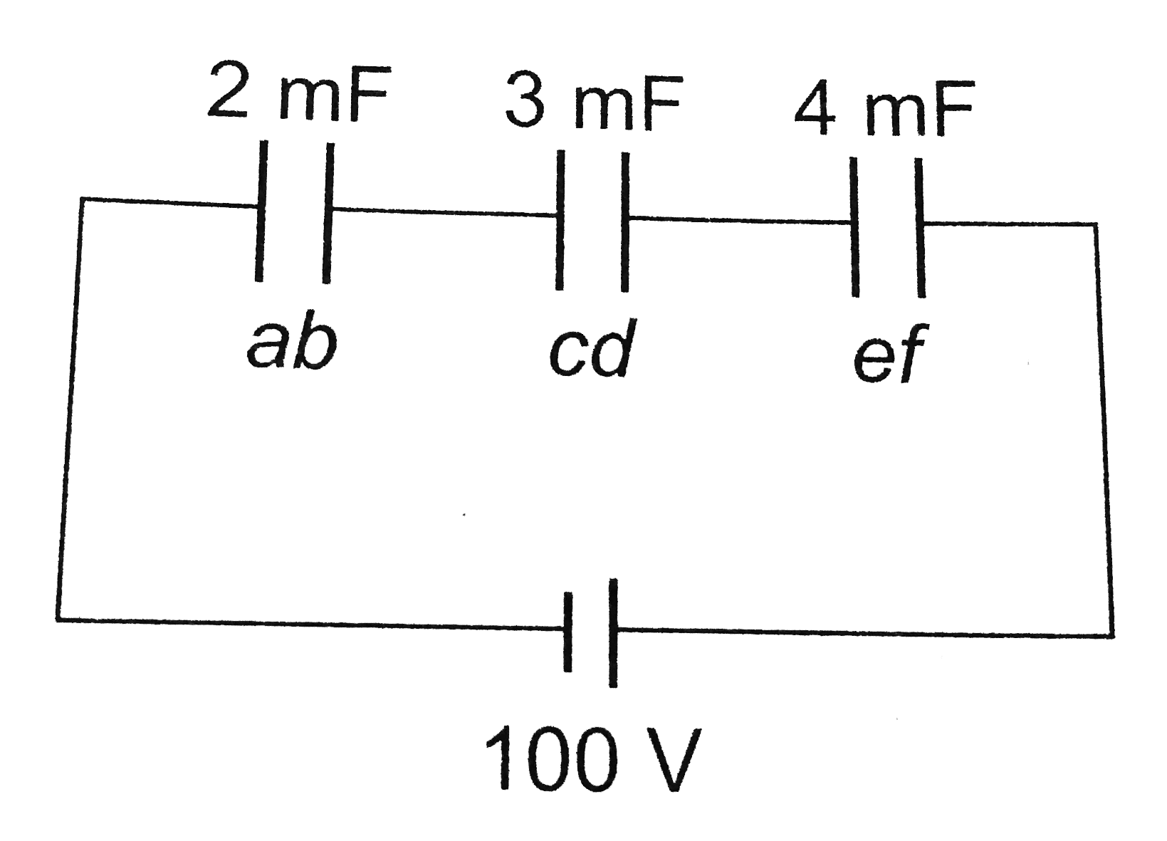
View SolutionThree capacitors are connected to `D.C` source of `100` volts shown in the adjoining figure. If the charge accumulated on plates of `C_(1), C_(2)` and `C_(3)` are `q_(a), q_(b), q_(c ), q_(d), q_(e)` and `q_(f)` respectively, then
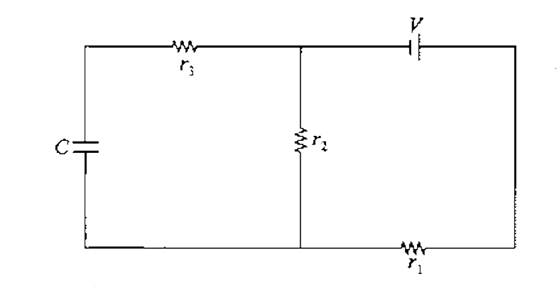
View SolutionIn the circuit shown in figure, the final voltage drop across the capacitor `C` is :
View SolutionThe plates of a parallel plate capacitor are charged up to `100 v`. Now, after removing the battery, a `2 mm` thick plate is inserted between the plates Then, to maintain the same potential deffernce, the distance betweem the capacitor plates is increase by `1.6 mm`. The dielectric canstant of the plate is .
View SolutionA capacitor is charged until its stored energy is `3J` and then the charging battery is removed. Now another uncharged capacitor is connected across it and it is found that charge is distributed equally in the two capacitors. The final value of total energy stored in the electric fields is :
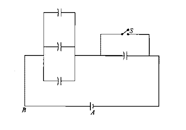
View SolutionFour capacitors of capacitance `10muF` and a battery of `200V` are arranged as shown. How much charge will flow through `AB` after the switch `S` is closed :
View SolutionA capacitor of capacitance of `2muF` is charged to a potential difference of `200V`, after disconnecting from the battery, it is connected in parallel with another uncharged capacitor. The final common potential is `20V` then the capacitance of second capacitor is :
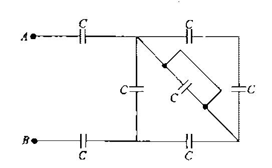
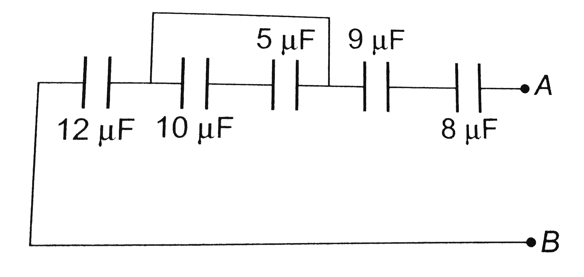
View SolutionThe equivalent capacitance between terminals `A` and `B` in the circuit shown in figure is:
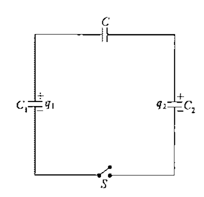
View SolutionTwo capacitor `C_(1)` and `C_(2)`, charged with charges`q_(1)` and `q_(2)` then these are connected in series with an uncharged capacitor `C`, as shown in figure. As the switch `S` is closed :
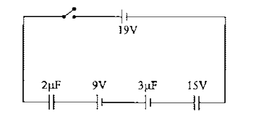
View SolutionThe two capacitors in the circuit shown in figure are initially uncharged and then connected as shown and switch is closed. What is the potential difference across `3muF` capacitor?
View SolutionA capacitor stores `50mu c` charge when connected across a battery . When the gap between the plates is filled with a dielectric , a charge of `100muc flows through the battery .Find the dielectric constant of the material inserted.
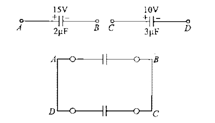
View SolutionInitially two capacitors are charged to different potential differences as shown in figure and then connected in parallel as shown. Which of the following is incorrect about this circuit?
View SolutionThe two spherical shells are at large separation, one of them has radius `10 cm` and `1.25 muC` charge. The other is of `20cm` radius and has `0.75 muC` charge. If they are connected by a conducting wire of negligible capacitance, the final charge on the shells are :
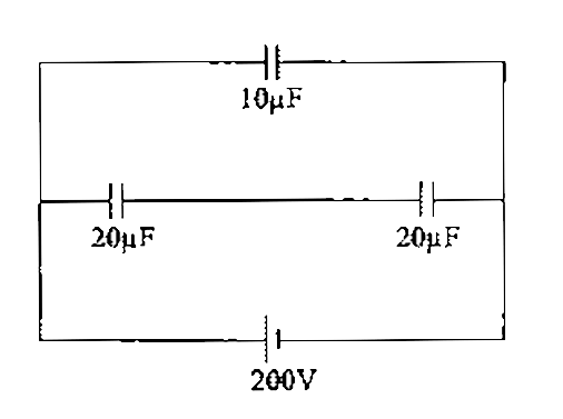
View SolutionIn the circuit shown in figure, charge on `10 muF` capacitor is given as
View SolutionA capacitor consists of two parallel metal plates of area `A` separated by a distance `d`. A dielectric slab of area `A`, thickness `b` and dielectric constant `k` is placed inside the capacitor. If `C_(k)` is the capacitance of capacitor with dielectric, under what limits the values of `k` and `b` are to be restricted so that`C_(k)=2C`, where `C` is capacitance without dielectric?
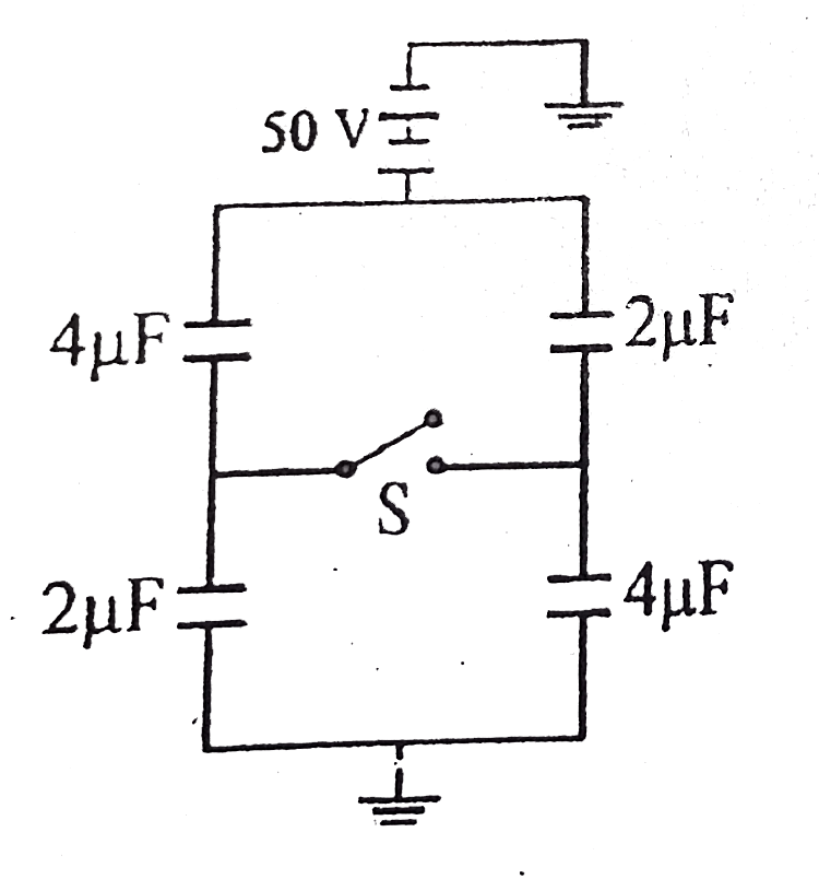
View SolutionThe circuit was in the shown state from a long time. Now the switch S is closed. The charged that flows through the switch is
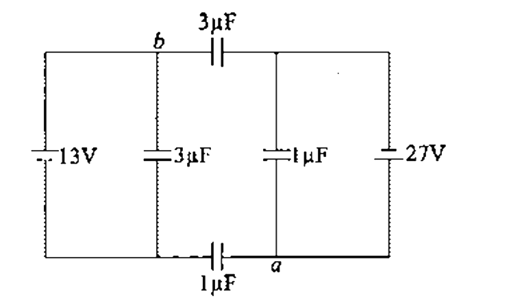
View SolutionFour capacitors and two batteries are connected as shown in the figure. The potential difference between the points `a` and `b` is:
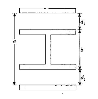
View SolutionTwo capacitors are made in series by two metal plates and one `I` structure as shown in figure. The area of each plate shown is `A`.The equivalent capacitance between top and bottom plate of this system is given as:
View SolutionA `3muF` and a `5muF` capacitor are connected in series across a `30V` battery. A `7muF` capacitor is then connected in parallel across the `3muF` capacitor. Choose the INCORRECT option :
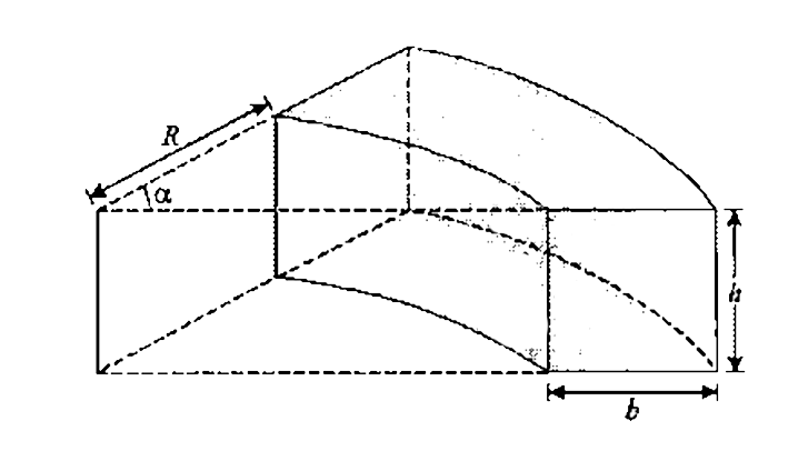
View SolutionFind the capacitance between the inner and outer curved cylindrical conductor surface as shown in figure. Space between conductor surface is filled with dielectric of dielectric constant `k`. Consider `b lt lt R`:
View SolutionThree capacitors of capacitances `3 muF, 9muF` and `18 muF` are connected one in series and another time in parallel. The ratio of equivalent capacitance in the two cases `((C_(s))/(C_(p)))` will be
View SolutionA capacitor of capacitance `C_(1)=1 muF` withstand a maximum voltage of `V_(1)=6 KV`, and another capacitor of capacitance `C_(2)=2 muF`, can with stand a maximum voltage of `V_(2)=4KV`. If they are connected in series, what maximum voltage will the system withstand?
View SolutionA `4muF` condenser is charged to `400V` and then its plates are joined through a resistance of `1KOmega`. The heat produced in the resistance is :
View SolutionCondenser `A` has a capacity of `15 muF` when it is filled with a medium of dielectric constant `15`. Another condenser `B` has a capacity `1muF` with air between the plates. Both are charged separately by a battery of `100V`. After charging, both are connected in parallel without the battery and the dielectric material being removed. The common potential now is
View SolutionTwo capacitors `2muF` and `4muF` are connected in parallel. A third capacitor of `6muF`is connected in series. The combination is then connected across a `12V` battery. The voltage across `2muF` capacitor is:
View SolutionThere is an air filled 1pF parallel plate capacitor. When the plate separation is doubled and the space is filled with wax, the capacitance increases to 2pF. The dielectric constant of wax is
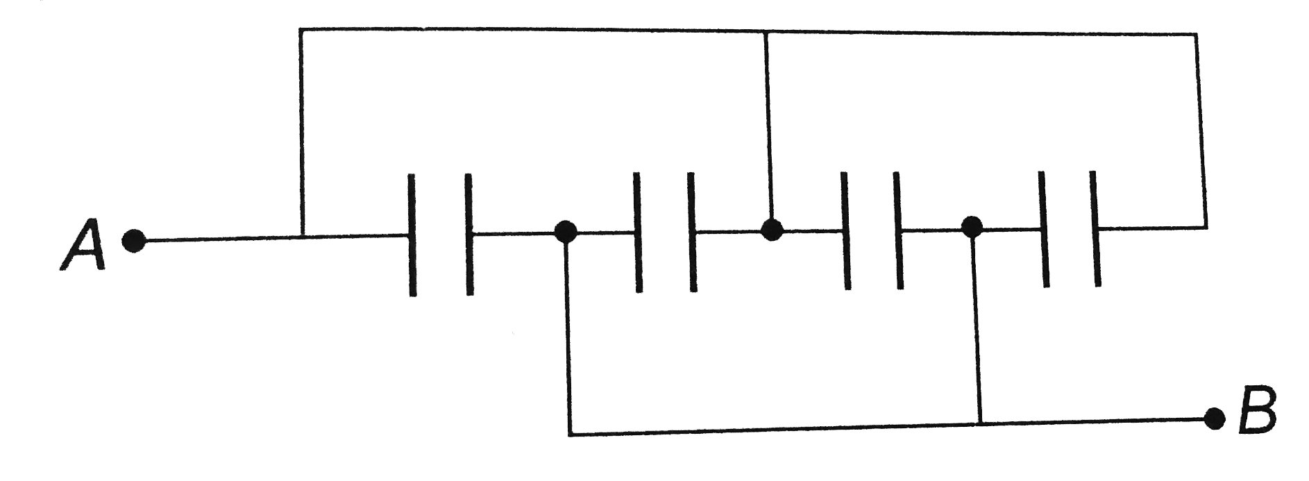
View SolutionFour condenser are joined as shown in the adjoining figure. The capacity of each is `8 muF`. The equivalent capacity between the points `A` and `B` will be
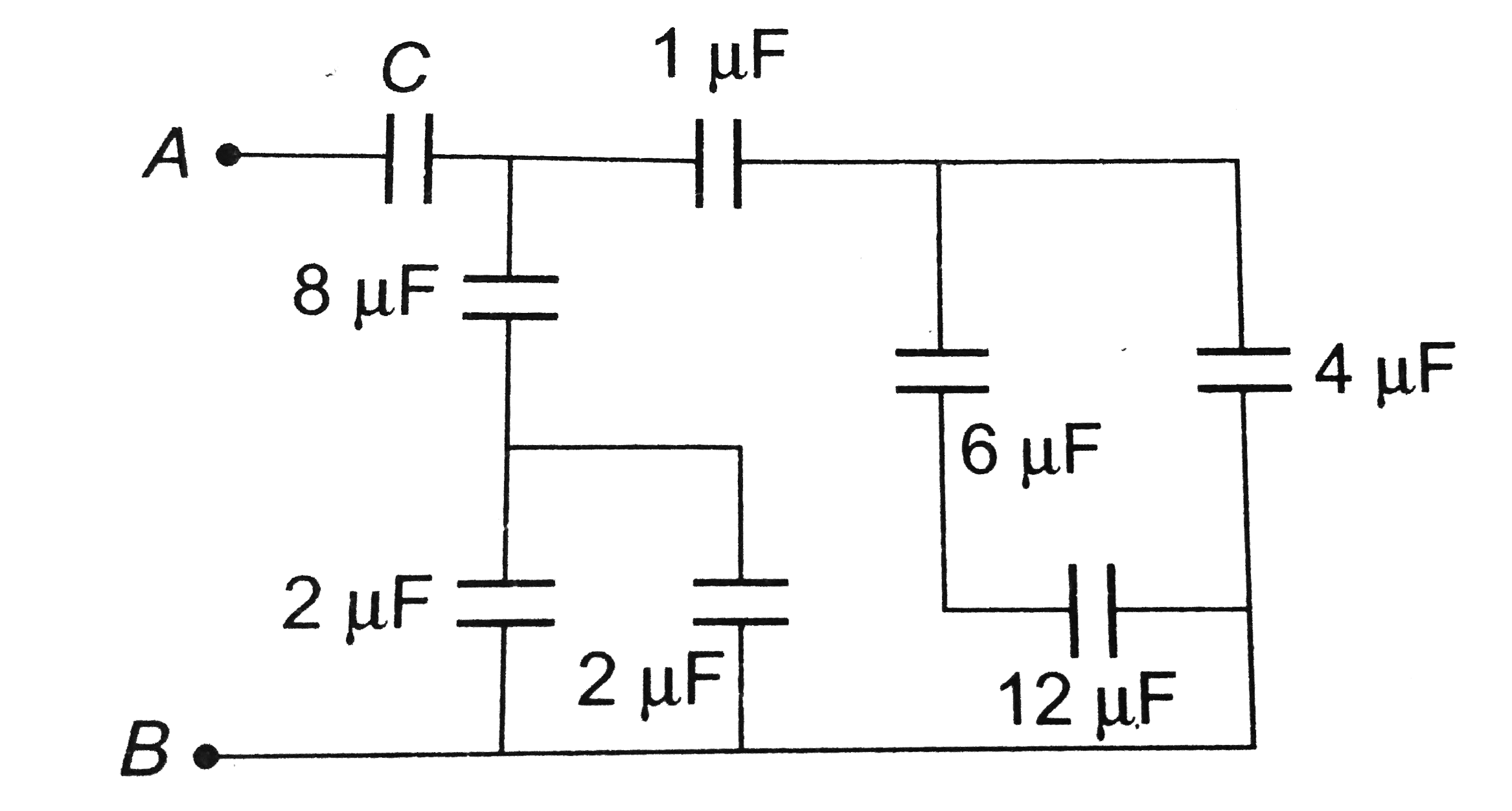
View SolutionIn the following circuit, the resultant capacitance between `A` and `B` is `1muF`. Then value of `C` is
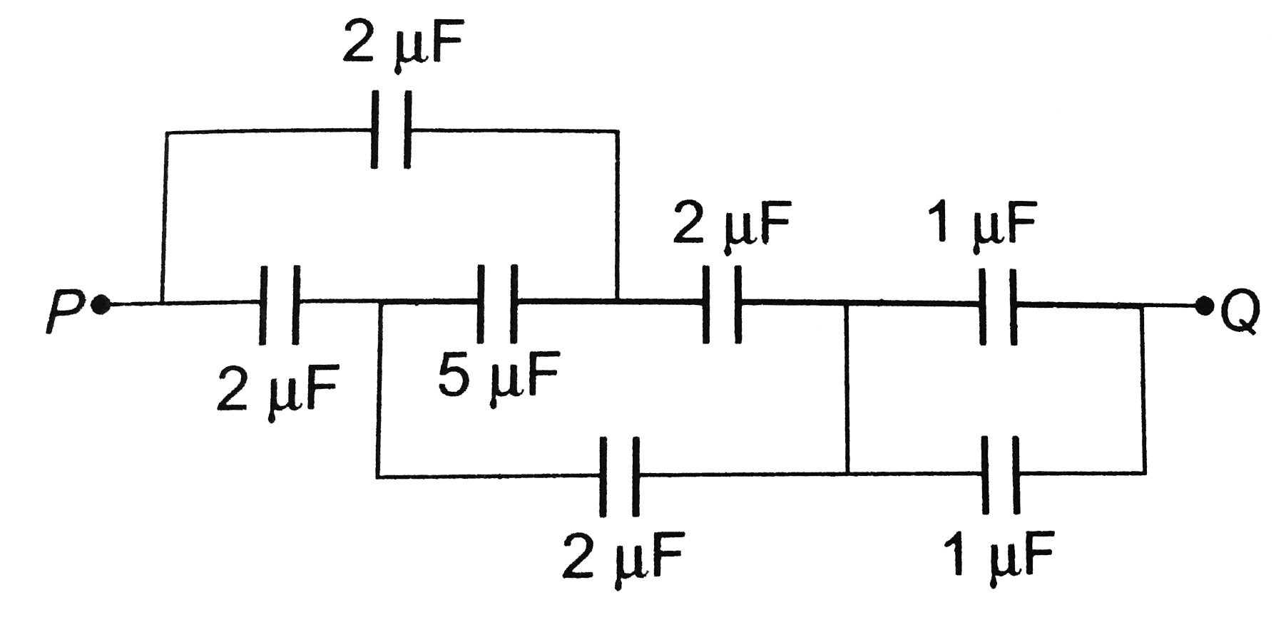
View SolutionThe effective capacitance between the points `P` and `Q` of the arrangement shown in the figure is
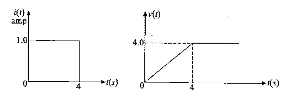
View SolutionA circuit element is placed in a blackbox. At `t=0`, a switch is closed and the current flowing through the circuit element and the voltage across its terminals are recorded to have the wave shapes shown in the figure here. The type of element and its magnitude are:
View SolutionTwo parallel plate capacitors of capacitances C and 2C are connected in parallel and charged to a potential difference V. The battery is then disconnected and the region between the plates of the capacitor C is completely filled with a material of dielectric constant K. The potential differences across the capacitors now becomes...........
View SolutionIn a circuit shown in the figure, what is potential of point `A`?

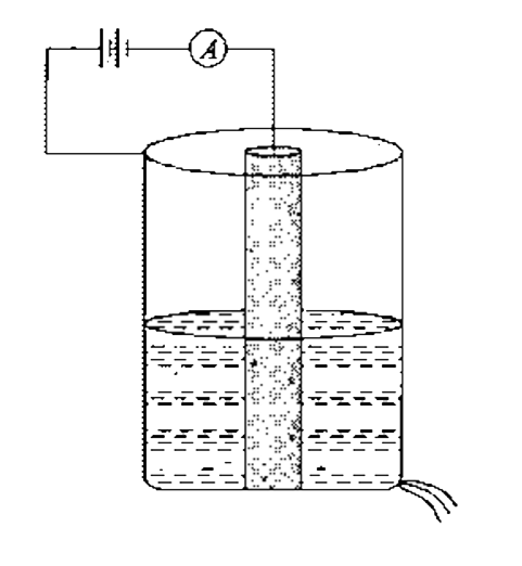
View SolutionTwo long coaxial cylindrical metal tubes stand on an insulatiog floor as shown in figure. A dielectric oil is filled in the annular region between the tubes. The tubes are maintained at a constant potential difference `V`. A small hole is opened at bottom then :
View Solution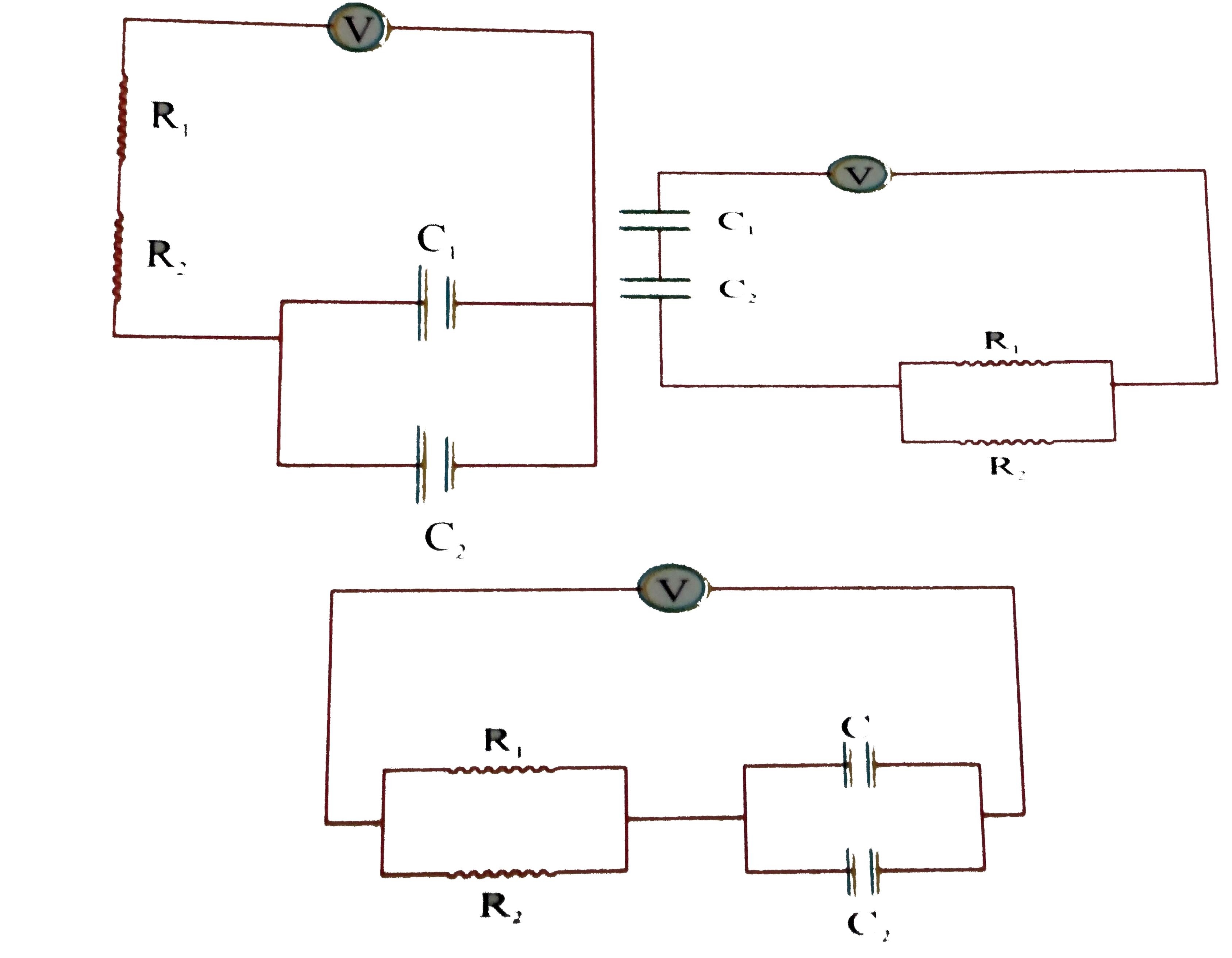
Find the time constant for the given RC circuits in correct order (in `mus`)
`R_(1)=1Omega,R_(2)=2Omega,C_(1)=4muF,C_(2)=2muF`
View SolutionThe capacities and connection of five capacitors are shown in the adjoining figure. The potential difference between the points `A` and `B` is `60` volts. Then the equivalent capacity between `A` and `B` and the charge on `5 muF` capacitance will be respectively
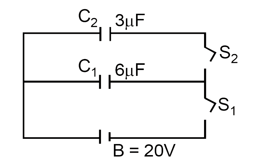
View SolutionIn the circuit shown here `C_(1) = 6muF, C2 = 3muF` and battery `B = 20V`. The Switch `S_(1)` is first closed. It is then opened and afterwards `S_(2)` is closed. What is the charge finally on `C_(2)`
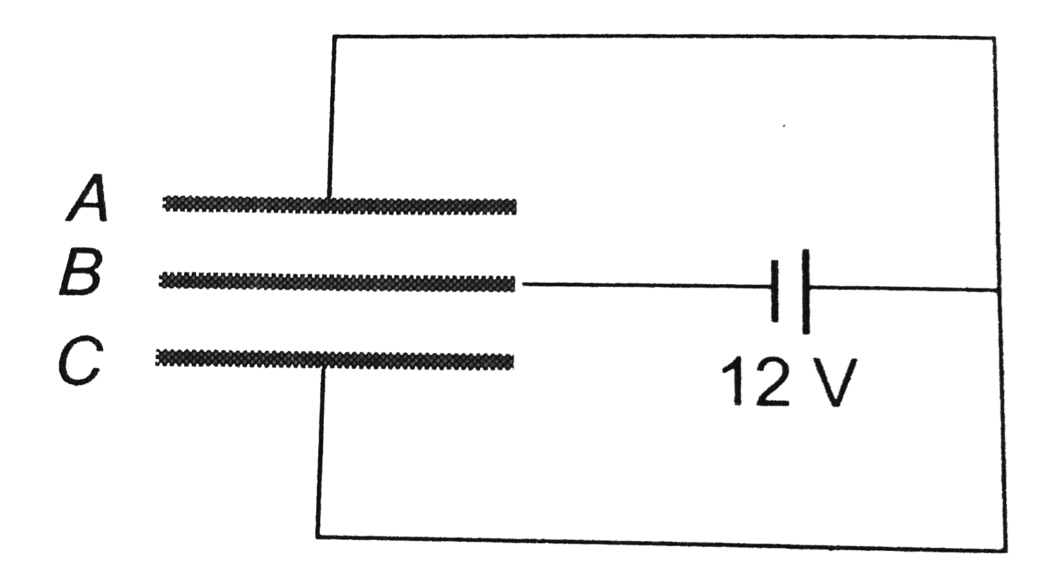
View SolutionThree plates `A, B, C` each of area `50 cm^(2)` have separation `3 mm` between `A` and `B mm` between `B` and `C`. The energy stored when the plates area fully charged is
View SolutionA fully charged capacitor has a capacitance 'C'. It is discharged through a small coil of resistance wire embedded in a thermally insulated block of specific heat capacity 's' and mass 'm'. If the temperature of the block is raised by 'DeltaT', the potential difference 'V' across the capacitance is
View SolutionA parallel plate capacitor with air between the plates has capacitance of `9pF`. The separation between its plates is 'd'. The space between the plates is now filled with two dielectrics. One of the dielectrics has dielectric constant `k_1=3` and thickness `d/3` while the other one has dielectric constant `k_2=6` and thickness `(2d)/(3)`. Capacitance of the capacitor is now
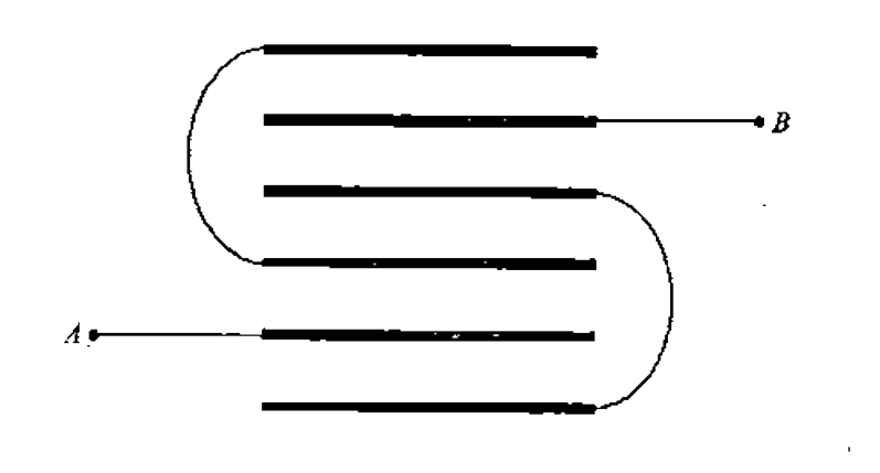
View SolutionSix plates each of area `A` arranged as shown· in figure. The separation between adjoining plates is `d`. Find the equivalent capacitance between points `A` and `B` :
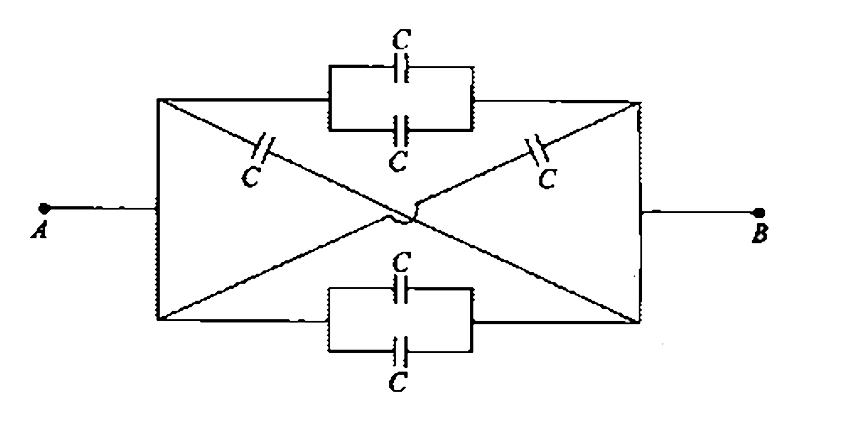
View SolutionSix capacitors each of capacitance of `2muF` are connected as shown in the figure. The effective capacitance between `A` and `B` is:
View SolutionWhat is equivalent capacitance of ladder circuit shown in figure between points `A` and `B`?

View SolutionFind the equivalent capacitance between terminals `A` and `B` in the circuit shown in figure:
View SolutionCircuit in figure shows three capacitors with capacitance and their breakdown voltage. What should be maximum value of the external source voltage such that no capacitor breaks down ?
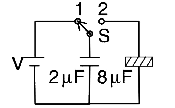
View SolutionA `2muF` capacitor is charged as shown in the figure. The percentage of its stored energy disispated after the switch S is turned to poistion 2 is
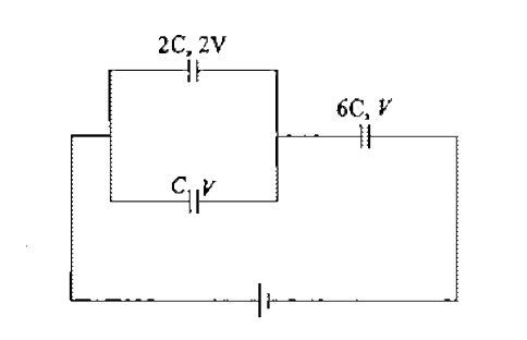
View SolutionFor the circuit shown in figure, which of the below options given is/are correct:
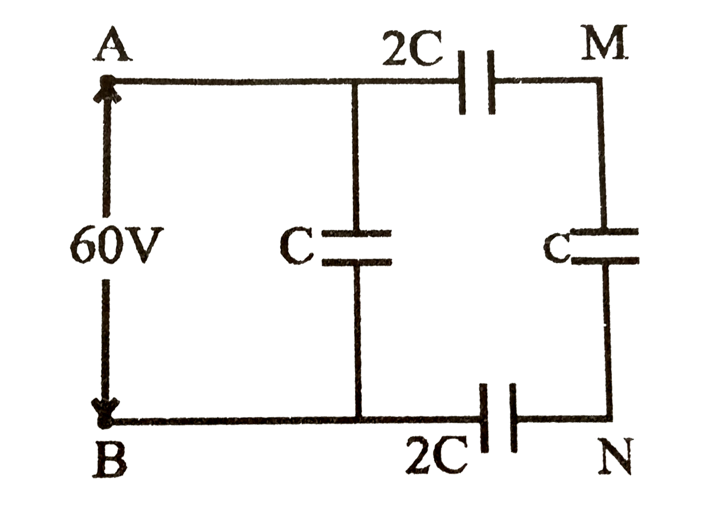
View SolutionIn the circuit shown, a potential difference of `60V` is applied acrodd.`AB`. The potential difference between the point `M` and `N` is-
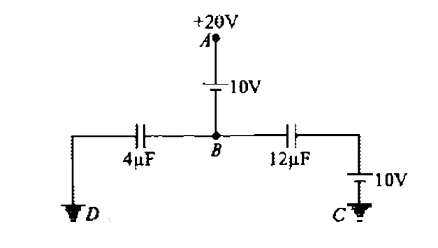
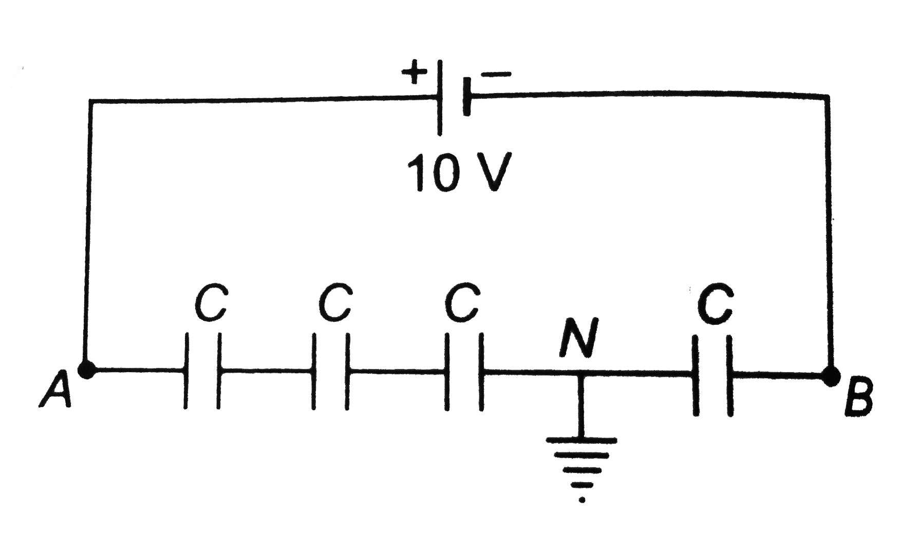
View SolutionFour identical capacitors are connected in series with a `10 V` battery as shown in the figure. The point `N` is earthed. The potentials of points `A` and `B` are
 `
`
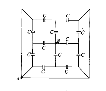
View SolutionFind the equivalent capacitance across `A` and `B` for the arrangement shown in figure. All the capacitors are of capacitance `C`
 `
`
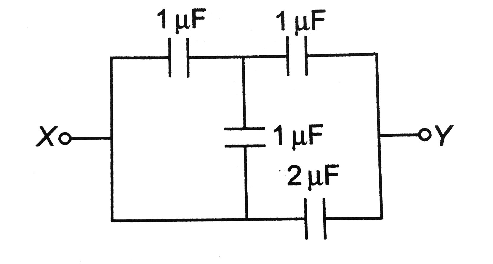
View SolutionThe equivalent capacitance between `X` and `Y` is
 `
`
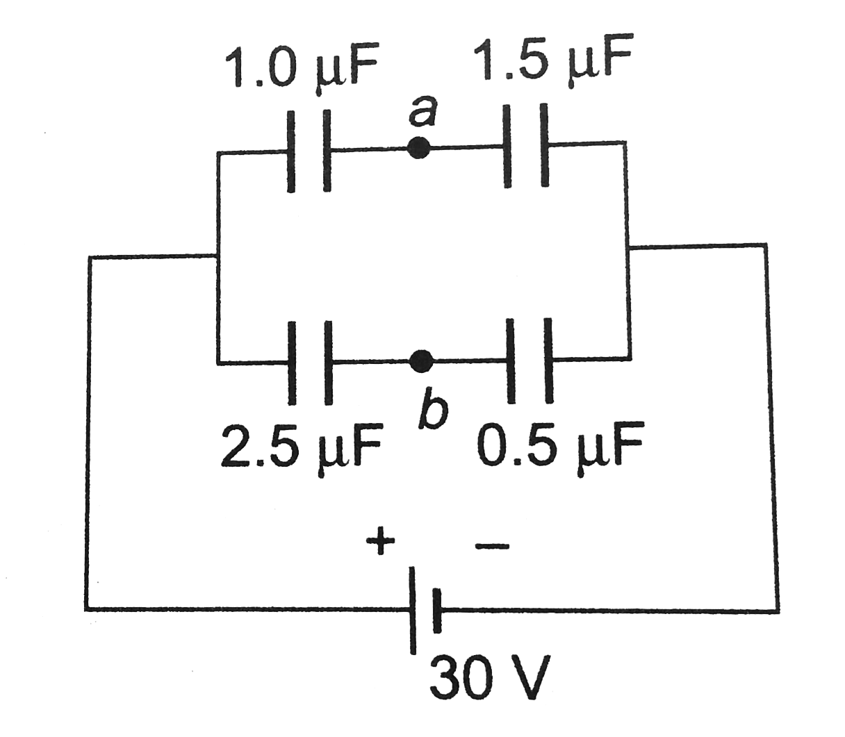
View SolutionFour capacitors are connected as shown in figuere to a `30 V` battery. The potential difference between points `a` and `b`
View SolutionThe distance between the plates of a charged plate capacitor disconnected from the batteryis 5cm and the intensity of the field in it is `E=300V//cm`. An uncharged metal bar `1cm` thick is introduced into the capacitor parallel to its planes. The potential difference between the plates now is :
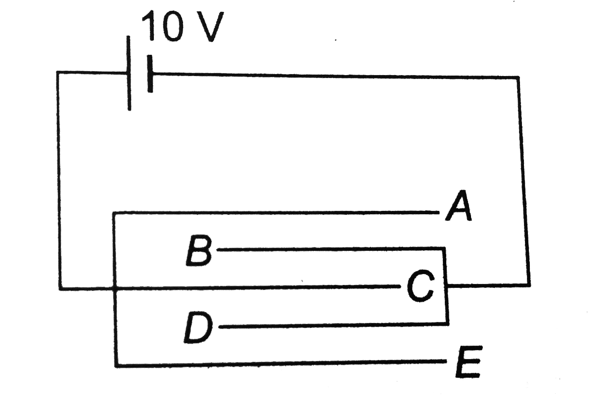
View SolutionFive identical capacitor plates are arranged such that they make four capacitors each of `2muF.` The plates are connected to a source of emf `10 V`. The charge on plate `C` is
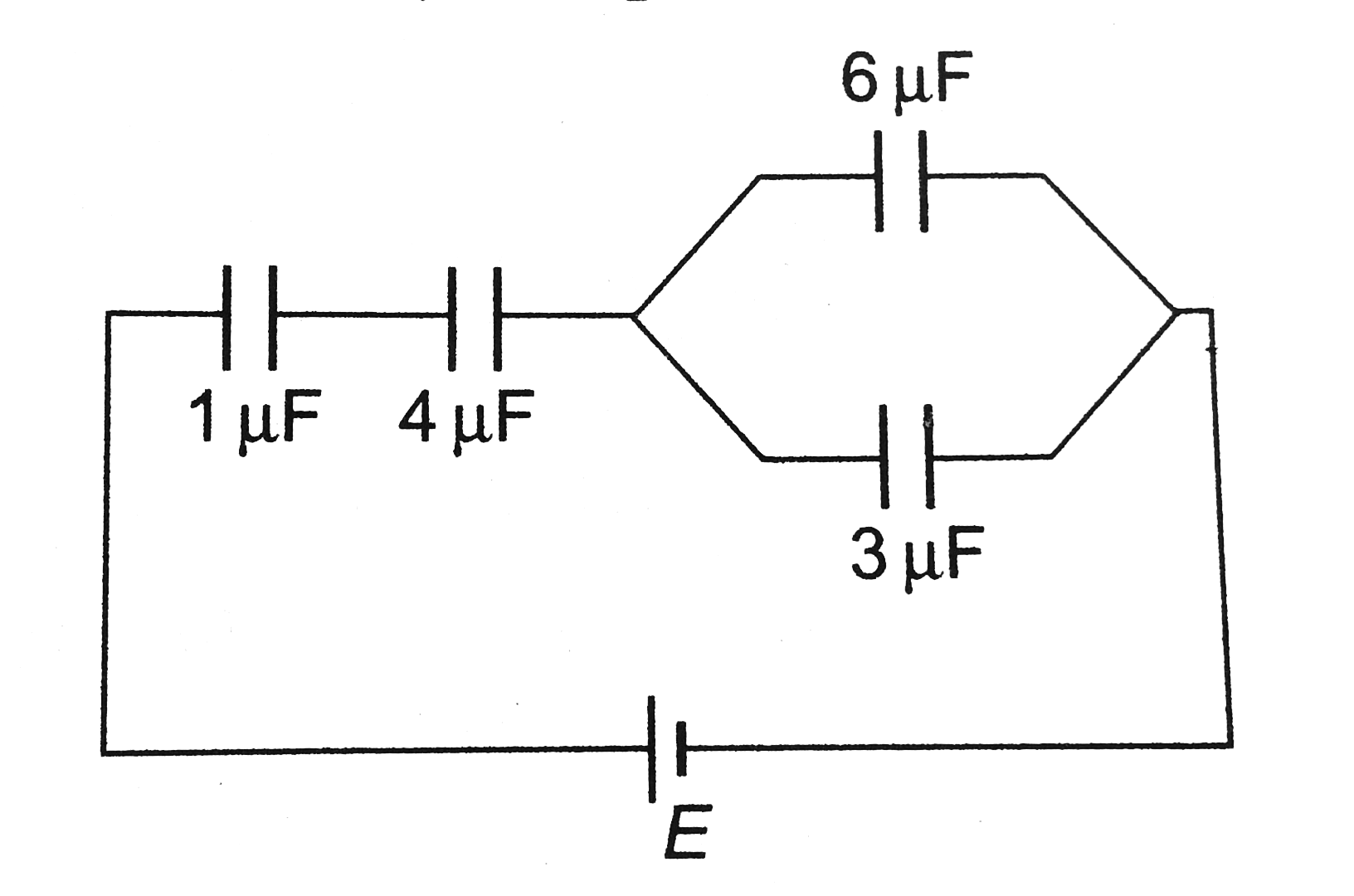
View Solutiongiven that potential differene across `1muF` capacitor is `10V`. Then,
View SolutionA capacitor of capacity `C` is charged to a potential difference `V` and another capacitor of capacity `2C` is charged to a potential difference `4V`. The charged batteries are disconnected and the two capacitors are connected with reverse polarity (i.e. positive plate of first capacitor is connected to negative plate of second capacitor). The heat produced during the redistribution of charge between the capacitors will be
View Solution
NUMERICAL MCQS questions and complete solutions for chapter CAPACITANCE of GK PUBLICATIONS PHYSICS (HINGLISH) of Class 12