In the figure below the switches S1 and S2 are closed simultaneously at t = 0 and a current starts to flow in the circuit. Both the batteries have the same magnitude of the electromotive force emf and the polarities are as indicated in the figure. Ignore mutual inductance between the inductors. The current I in the middle wire reaches its maximum magnitude Imax at time t = τ. Which of the following statements is are true?A Imax = V/2RB Imax = V/4RC τ = L/Rln2D τ = 2L/Rln2
Related Solutions
In the figure below, the switches S_(1) and S_(2) are closed simultaneously at t =0 and a current starts to flow in the circuit. Both the batteries have the same magnitude of the electromotive force (emf) and the polarities are as indicated in the figure. Ignore mutual inductance between the inductors. The current ? in the middle wire reaches its maximum magnitude I_(max) at time t=tau . Which of the following statements is (are) true?
View SolutionIn the figure below, the switches S_(1) and S_(2) are closed simultaneously at t =0 and a current starts to flow in the circuit. Both the batteries have the same magnitude of the electromotive force (emf) and the polarities are as indicated in the figure. Ignore mutual inductance between the inductors. The current ? in the middle wire reaches its maximum magnitude I_(max) at time t=tau . Which of the following statements is (are) true? A. I_("max")=(V)/(2R) B. I_("max")=(V)/(4R) C. tau=(L)/( R)""l n2 D. tau=(2L)/( R)" l n2
View SolutionIn the figure given below, the electromotive force associated with an inductor L and a resistor R in series order varepsilon Indicates the battery. If the switch is closed at t = 0, then what is the total charge flowing through the battery at a time constant of the circuit?
View SolutionConsider a circuit consists of resistors, inductor, battery and a switch as shown. Resistance of resistors, inductance of inductor and of battery are indicated. The switch is closed at .
Find time constant of LR circuit during growth of currentView SolutionIn the circuit shown in figure switch S is closed at time t=0
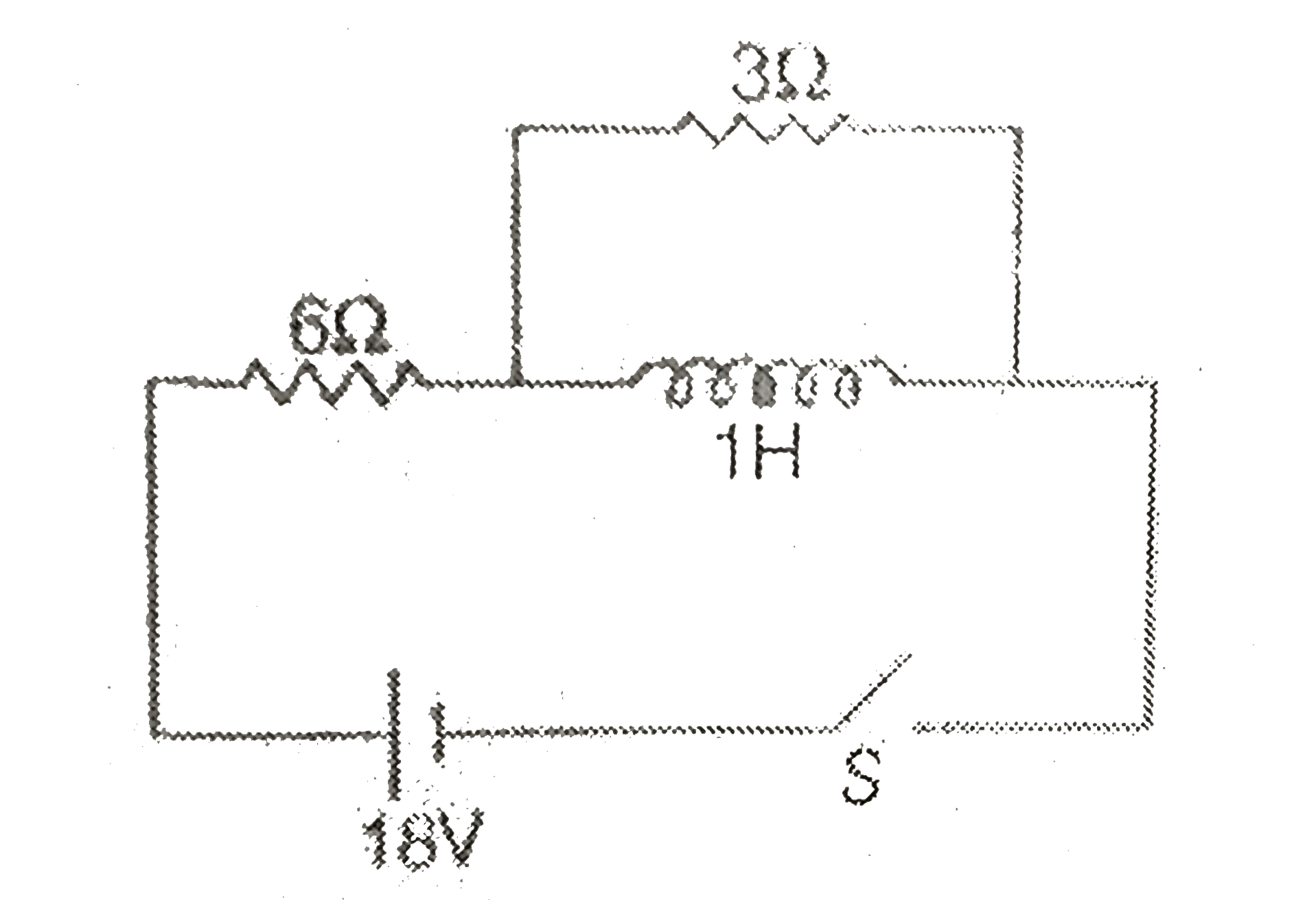
Current I from the battery at time t is given byView SolutionIn the circuit shown in figure switch S is closed at time t=0

Current I from the battery at time t is given byView Solutionएक चुंबकीय क्षेत्र का आयाम . है , जो निर्वात में एक समस्वर विद्युत चुम्बकीय तरंग का हिस्सा है, तरंग के विद्युत क्षेत्र का आयाम क्या है?
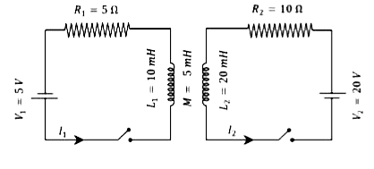
View Solutionचित्रानुसार, दो LR परिपथों (circuits) के प्रेरकों (inductors) को एक दूसरे के समीप रखा गया है। प्रेरकों का स्व-प्रेरकत्व (self-inductance), प्रतिरोध, अन्योन्य-प्रेरकत्व (mutual inductances) एवं अनुप्रयुक्त वोल्टता (applied voltages) का मान परिपथ में दिया गया है। दोनों स्विचों को एक साथ बंद (on) करने के पश्चात् जब विद्युत् धाराएं अपनी स्थायी अवस्था (steady state) में पहुँचती हैं, तब तक प्रेरकों में प्रेरित विद्युत्-वाहक बल के विरुद्ध बैटरियों द्वारा किया गया कुल कार्य ______mJहै।
 View Solution
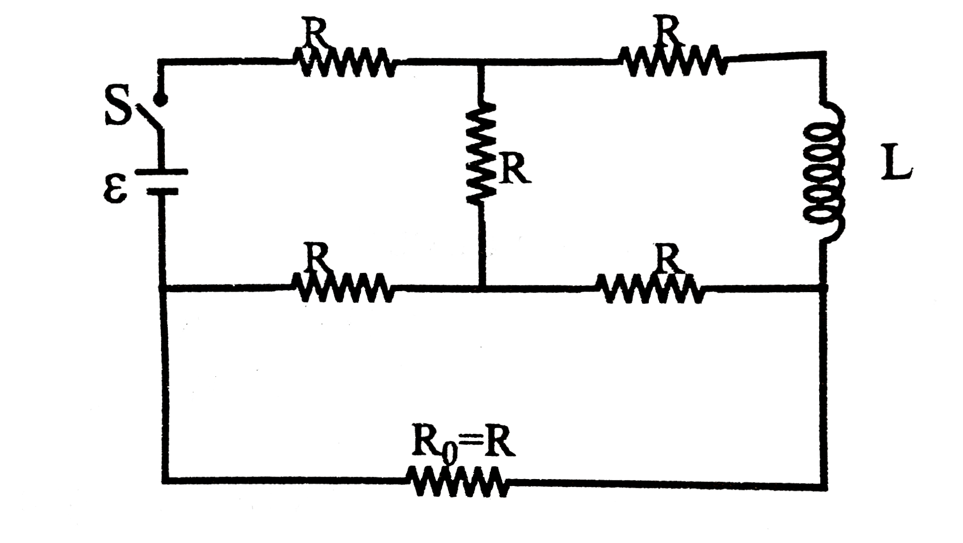
Consider a circuit consists of resistors, inductor, battery and a switch as shown. Resistance of resistors, inductance of inductor and of battery are indicated. The switch is closed at .
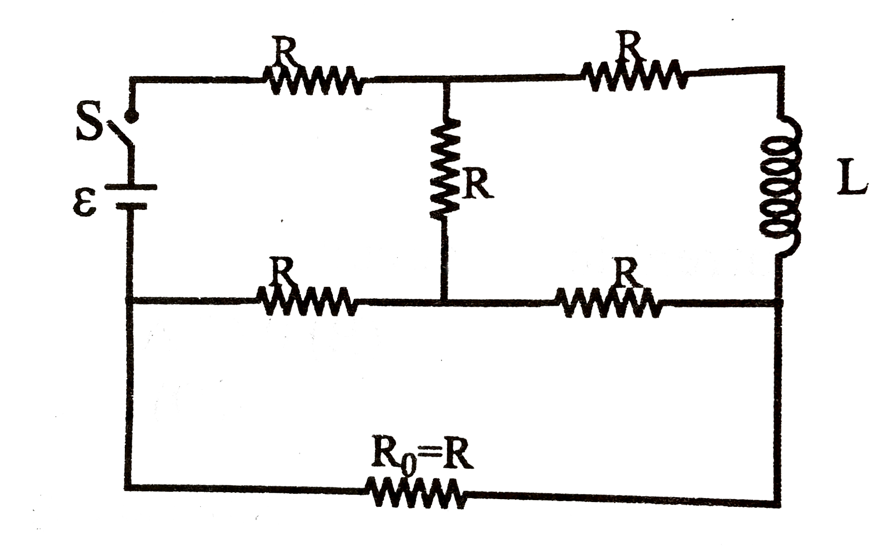
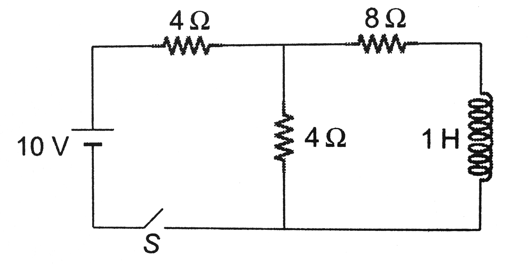
Find current through at steady stateView SolutionThe switch in figure is closed at time . Find the current in the inductor and the current through the switch as functions of time thereafter.
 View Solution
The switch in figure is closed at time t = 0 . Find the current in the inductor and the current through the switch as functions of time thereafter.
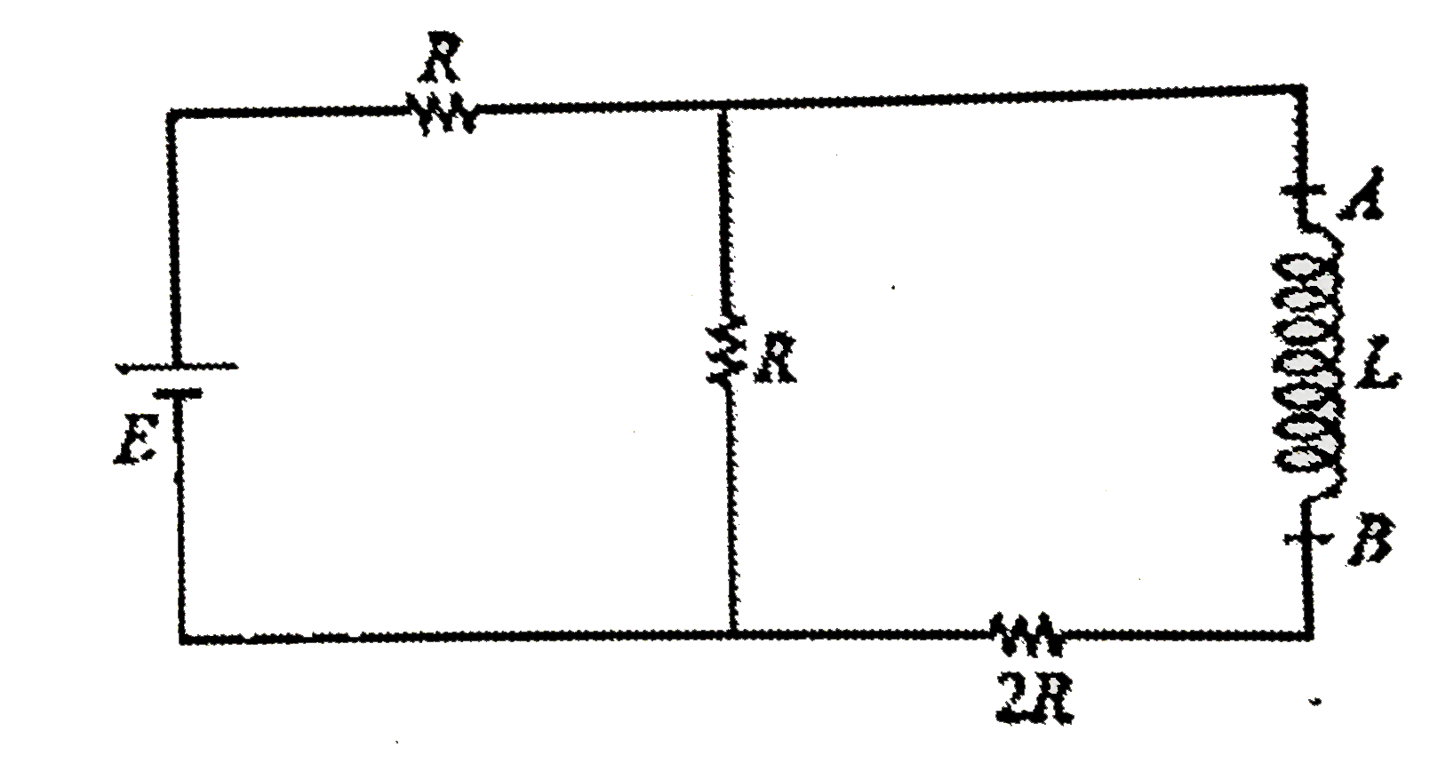
View SolutionFigure-5.102 shows a RL circuit. If at t-0 switch is closed, find the current in inductor as a function of time.
 View Solution
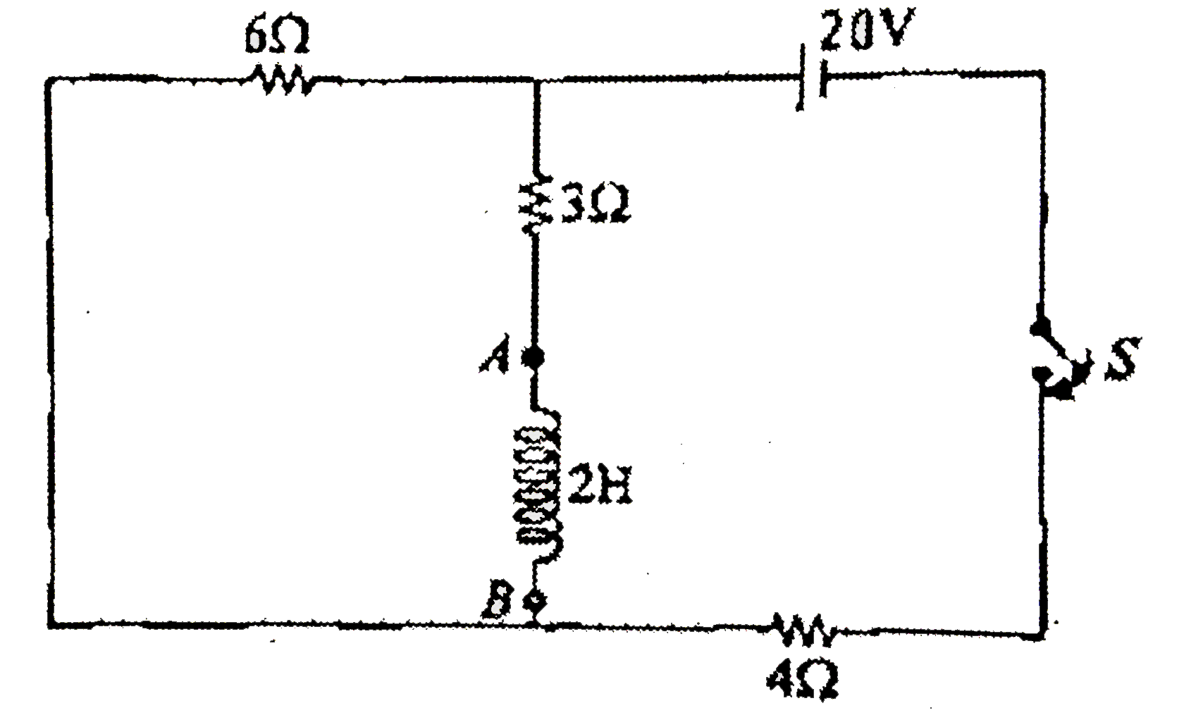
In the circuit shown in figure-5.115, find the current in inductor as a function of time if switch is closed at t=0.
 View Solution
In the given circuit, the switch K_2 is opened and the switch K_1 is closed at time t=0. At time t=t_0 , the switch K_1 is opened and the switch K_2 is simultaneously closed. Sketch the variation of the inductor current I with time.
View SolutionA resistor and inductor are connected in series through a battery. The switch is closed at time t=0 . Then what is the magnitude of current flowing when rate of increases of magnetic energy in the inductor is maximum
View SolutionAs shown in the figure, a battery of emf is connected to an inductor L and resistance R in series. The switch is closed at . The total charge that flows from the battery, between t=t_e and t=2t_e ( t_e is the time constant of the circuit) is:
View SolutionAs shown in the figure, a battery of emf is connected to an inductor L and resistance R in series. The switch is closed at . The total charge that flows from the battery, between t=t_e and t=2t_e ( t_e is the time constant of the circuit) is:
View SolutionThe figure below shows a battery of emf epsilon connected to an inductor L and resistance R in series. If the switch is closed at t=0, then the total charge that flows from the battery in time constant of the circuit is
View SolutionThe figure below shows a battery of emf epsilon connected to an inductor L and resistance R in series. If the switch is closed at t=0, then the total charge that flows from the battery in time constant of the circuit is
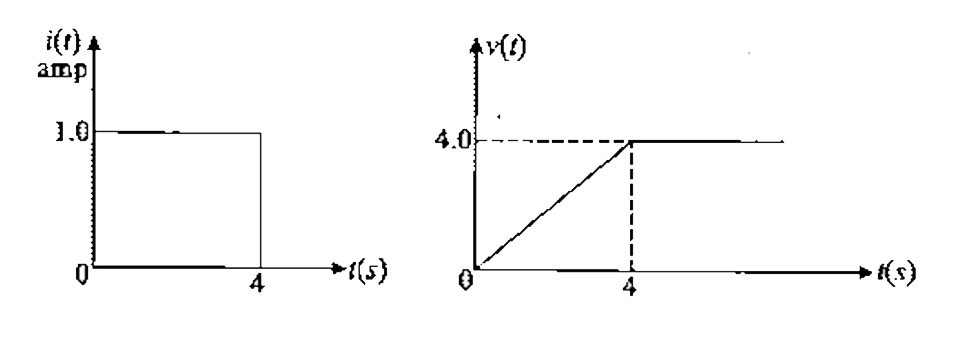
View SolutionA circuit element is placed in a blackbox. At , a switch is closed and the current flowing through the circuit element and the voltage across its terminals are recorded to have the wave shapes shown in the figure here. The type of element and its magnitude are:
 View Solution
