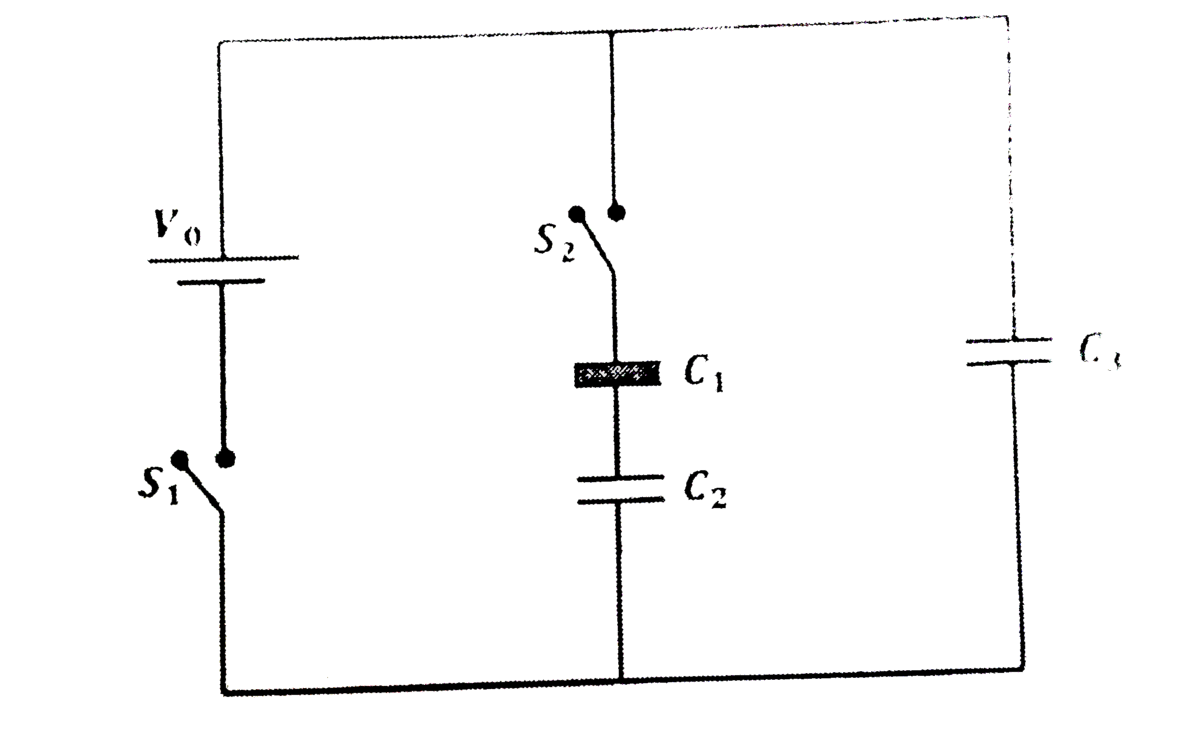
Three identical capacitors C1 C2 and C3 have a capacitance of 1.0μF each and they are uncharged initially. They are connected in a circuit as shown in the figure and C1 is then filled completely with a dielectric material of relative permittivity ∈r. The cell electromotive force emf V0 = 8V. First the switch S1 is closed while the switch S2 is kept open. When the capacitor C3 is fully charged S1 is opened and S2 is closed simultaneously. When all the capacitors reach equilibrium the charge on C3 is found to be 5μC. The value of ∈r.
Related Solutions
Three identical capacitors C_(1),C_(2) and C_(3) have a capacitance of 1.0 mu F each and they are uncharged initially. They are connected in a circuit as shown in the figure and C_(1) is then filled completely with a dielectric material of relative permittivity epsilon_(r) . The cell electromotive force (emf) V_(0)=8V . First the switch S_(1) is closed while the switch S_(2) is kept open. When the capacitor C_(3) is fully charged, S_(1) is opened and S_(2) is closed simultaneously. When all the capacitors reach equilibrium, the charge on C_(3) is found to be 5 mu c . The value of epsilon_(r) = ____________.
View SolutionThree identical capacitors and have a capacitance of each and they are uncharged initially. They are connected in a circuit as shown in the figure and is then filled completely with a dielectric material of relative permittivity . The cell electromotive force (emf) . First the switch is closed while the switch is kept open. When the capacitor is fully charged, is opened and is closed simultaneously. When all the capacitors reach equilibrium, the charge on is found to be . The value of = ____________.
 View Solution
In the given figure switch is open initially and capacitor C_2 is unchanged Energy in C1 is
View SolutionIn the given figure switch is open initially and capacitor C_2 is unchanged Energy in C1 is
View SolutionTwo circuits (a) and (b) have charged capacitors of capacitance C. 2C and 3C with open switches. Charges on each of the capacitor are as shown in the figures. On closing the switches
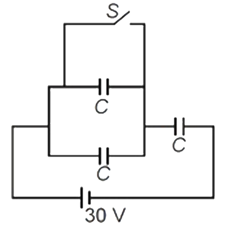
View SolutionThree capacitors each of capacitance are connected with a battery of emf 30 V as shown in the figure . When the switch S is closed , the heat generated in the circuit will be
 View Solution
Three capacitors each of capacitance are connected with a battery of emf 30 V as shown in the figure . When the switch S is closed , the heat generated in the circuit will be
 View Solution
Five chairs C1, C2, C3, C4 and C5 are placed one above the other. If C1 is above C2, C3 is above C4 but below C5 and C4 is above C1, which chair is in the middle?
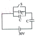
View SolutionThree capacitors each having capacitance C=2uF are connected with a battery of emf = 30V as shown in figure. When the switch S is closed.
 View Solution
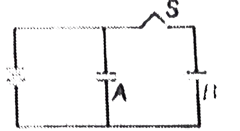
The figure shows two identical parallel plate capacitors connected to a battery with the switch S closed. The switch is now opened and the free space between the plates of the capacitors is filled with a dielectric of dielectric constant(or relative permittivity) 3. Find the ratio of the total electrostatic energy stored in both capacitors before and after the introduction of the dielectric.
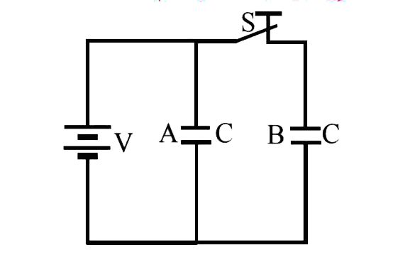
View SolutionThe figure shows two identical parallel plate capacitors connected to a battery with the switch S closed. The switch is now opened and the free space between the plates of the capacitors is filled with a dielectric of dielectric constant(or relative permittivity) 3. Find the ratio of the total electrostatic energy stored in both capacitors before and after the introduction of the dielectric.
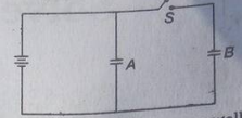
View SolutionTwo identical air filled parallel plate capacitors are charged to the same potential in the manner shown by closing the switch S. If now the switch S is opened and the space between the plates is filled with a dielectric of relative permittivity , then
 View Solution
Two identical air filled parallel plate capacitors are changed to the same potential in the manner shown by closing the switch S. If now the switch S is opened and the space between the plates is filled with a dielectric of relative permittivity , then
 View Solution
Two identical air filled parallel plate capacitors are changed to the same potential in the manner shown by closing the switch S. If now the switch S is opened and the space between the plates is filled with a dielectric of relative permittivity , then
 View Solution
In the given figure switch is open initially and capacitor is unchanged
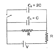
Charge on C2 just after closing the switch isView SolutionIn the given figure switch is open initially and capacitor is unchanged

Charge on C2 just after closing the switch isView SolutionThe two capacitors in the circuit shown in figure are initially uncharged and then connected as shown and switch is closed. What is the potential difference across 3muF capacitor?
View SolutionThree uncharged capacitors are connected in the circuit as shown. What should be the value of C3(in uF) so that potential difference across each capacitor is same
View Solution
