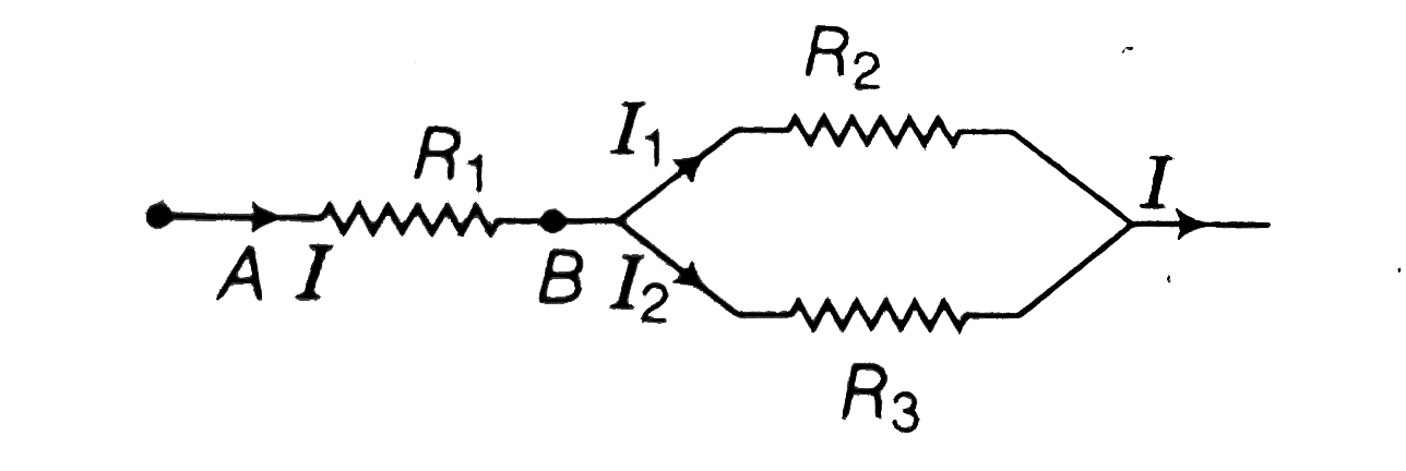
The circuit in figure, where there are three resistors R1,R2 and R3 . If the voltage between A and C is V, the current / is given by
V(R1+R2)R1R2+R1R3+R2R3
V(R1+R3)R1R2+R1R3+R2R3
V(R3×R2)R1R2+R1R3+R2R3
V(R2+R3)R1R2+R1R3+R2R3
The correct Answer is:D
We can replace R2 and R3 by an equivalent R23eq between point B and C with
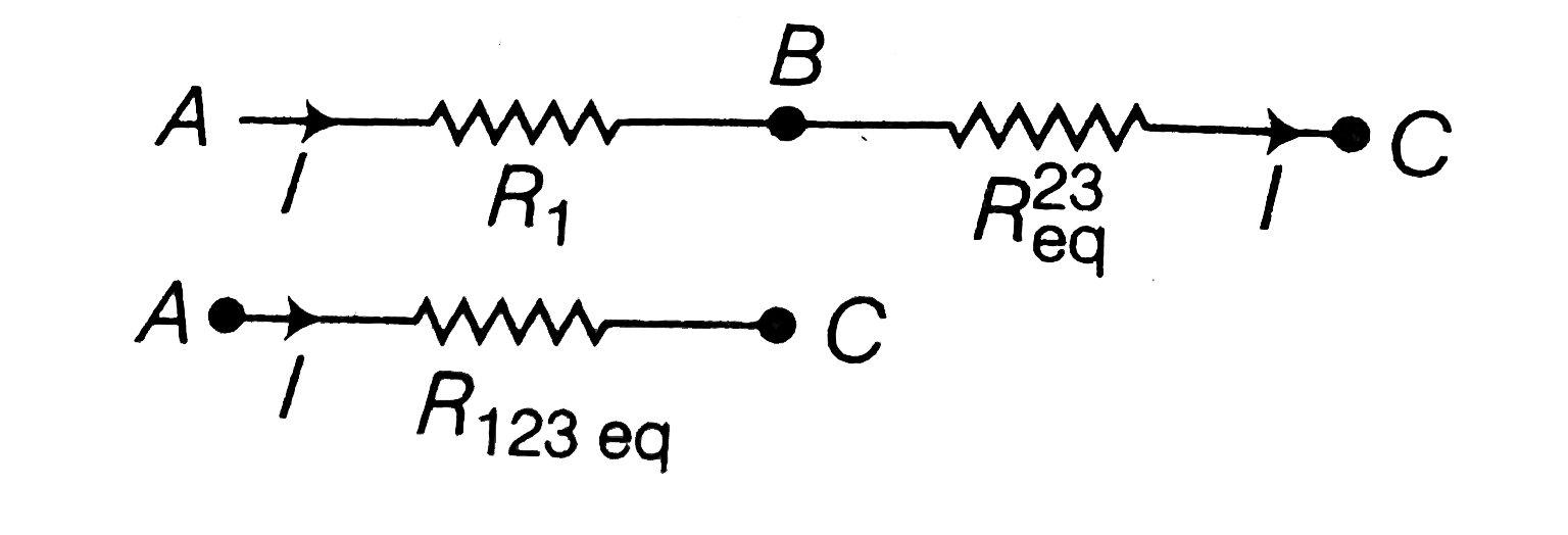
The circuit now has R1 and R23eq in series and hence their combination can be replaced by an equivalent resistance R123eq with
R123eq=R23eq+R1=R1+[R2R3R2+R3]
If the voltage between A and C is V, the current l is given by
l=VR123e=VR1+[R2R3/(R2+R3)]
=V(R2+R3)R1R2+R1R3+R2R3
Topper's Solved these Questions
- CURRENT ELECTRICITYBOOK - MHTCET PREVIOUS YEAR PAPERS AND PRACTICE PAPERSCHAPTER - CURRENT ELECTRICITYEXERCISE - EXERCISE 2
26 Videos
- CURRENT ELECTRICITYBOOK - MHTCET PREVIOUS YEAR PAPERS AND PRACTICE PAPERSCHAPTER - CURRENT ELECTRICITYEXERCISE - MHT CET CORNER
32 Videos
- CURRENT ELECTRICITYBOOK - MHTCET PREVIOUS YEAR PAPERS AND PRACTICE PAPERSCHAPTER - CURRENT ELECTRICITYEXERCISE - MHT CET CORNER
32 Videos
- COMMUNICATION SYSTEMBOOK - MHTCET PREVIOUS YEAR PAPERS AND PRACTICE PAPERSCHAPTER - COMMUNICATION SYSTEMEXERCISE - MHC CET Corner
6 Videos
- ELASTICITY BOOK - MHTCET PREVIOUS YEAR PAPERS AND PRACTICE PAPERSCHAPTER - ELASTICITY EXERCISE - MHT CET CORNER
16 Videos
Similar Questions
Knowledge Check
In the circuit shown in the given figure, the resistances R1andR2 are respectively
 A14Ωand40ΩB40Ωand44ΩC40Ωand30ΩD14Ωand30Ω
In the electrical circuit (ABC) as shown in the figure given below , the resistances R1,R2andR3 are same and equal to 30 . If a sour ce of voltage 2 V is connected across one arm, the current drawn from the voltage source is
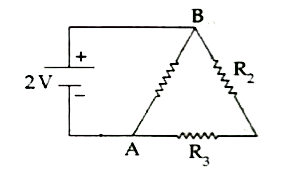 A15 AB110 AC115 AD145 A
Six resistances each of v ale r=6Ω are connected between points A,B and C as shown in the figure if R1,R2 and R3 are the net resistances between A and B, between B and C and between A and C respectively, the R1:R2:R3 will be equal to
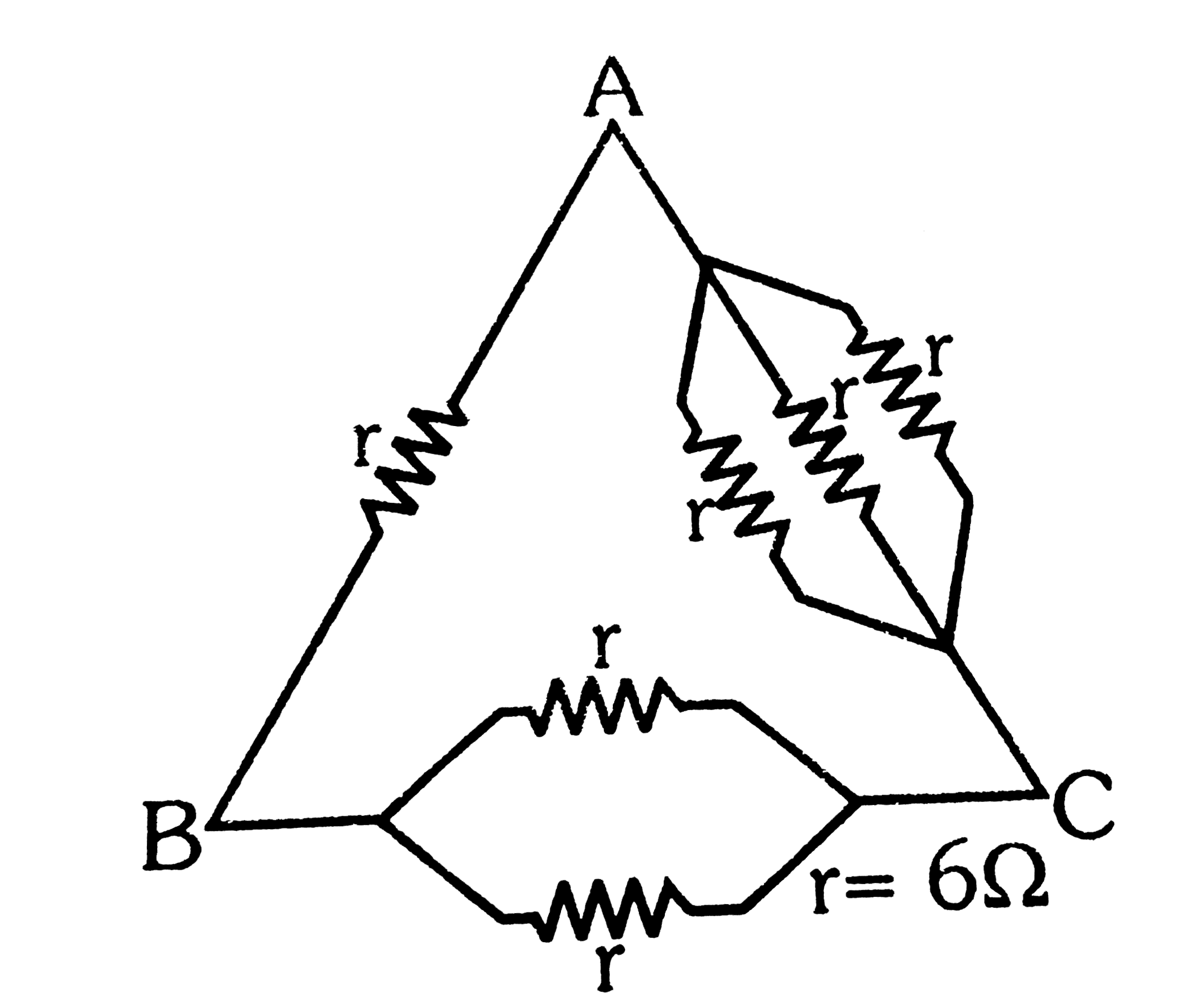 A6:3:2B1:2:3C5:4:3D4:3:2
The circuit diagram given below shows the combination of three resistors R1,R2 and R3:
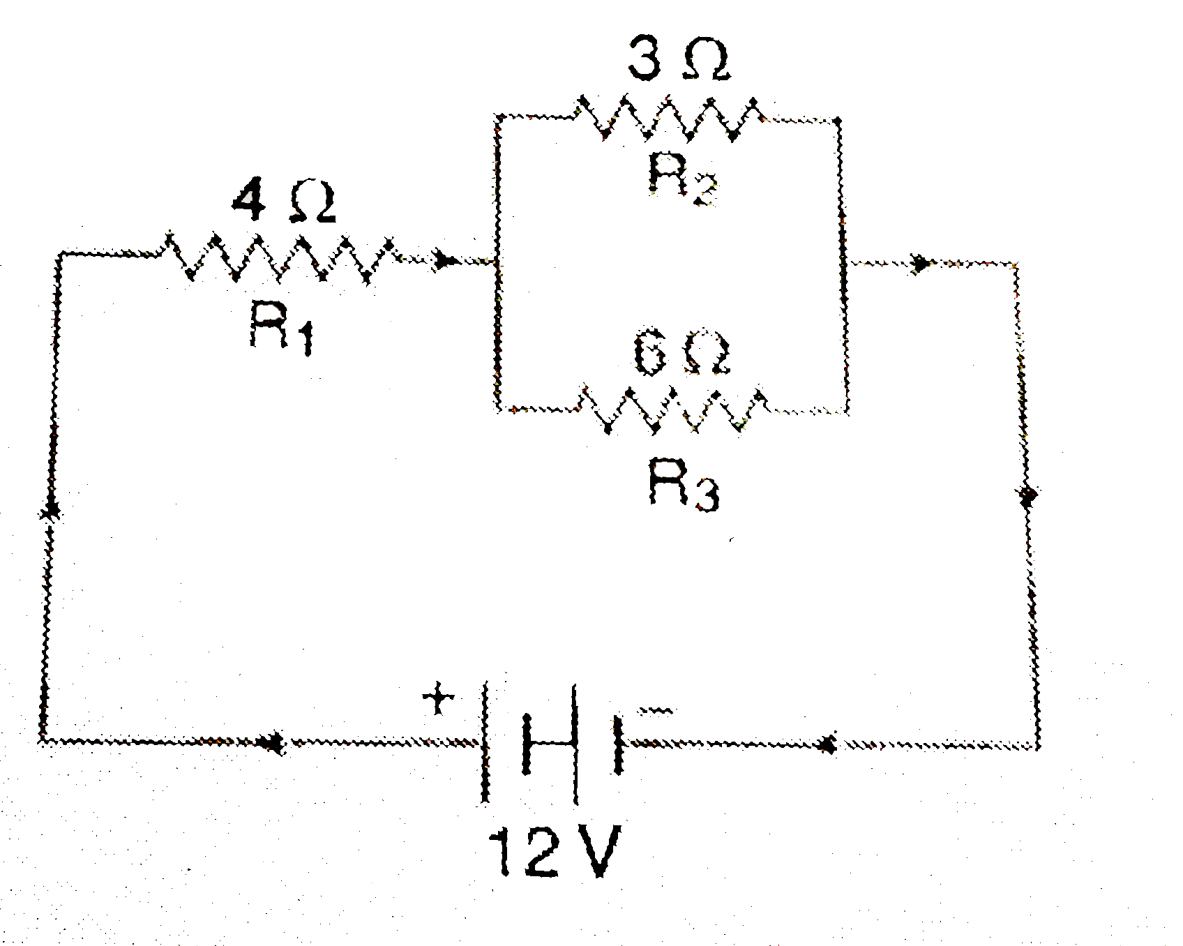
Find: (i) total resistance of the circuit.
(ii) total current flowing in the circuit.
(iii) the potential difference across R1.
View SolutionIn the circuit diagram given below, three resistors R1,R2, and R3 of 5Ω,10Ω and 30Ω, respectively are connected as shown.
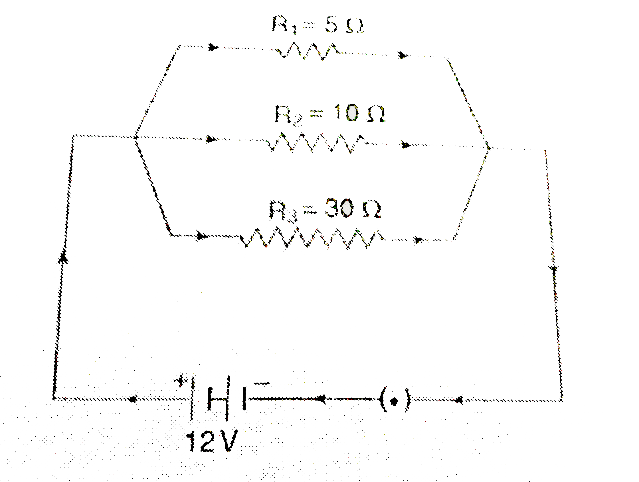
Calculate:
(a) current through each resistor.
(b) total current in the circuit.
(c) total resistance in the circuit.
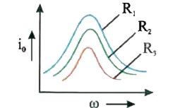
View SolutionThe graph between current and frequency for LCR series circuit is drawn for three different resistor R1,R2 & R3 . Which one is correct regarding resistance.
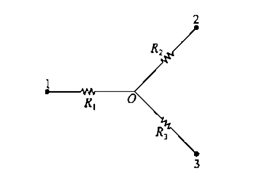
View SolutionFind the current flowing through the resistance R1 of the circuit shown in figure-3.103. the resistances are equal to R1=10Ω,R2=20Ω and R3=30Ω and the potentials of points 1,2 and 3 are given as V1=10V,V2=6V and V3=5V.
View SolutionIn the circuit shown in figure
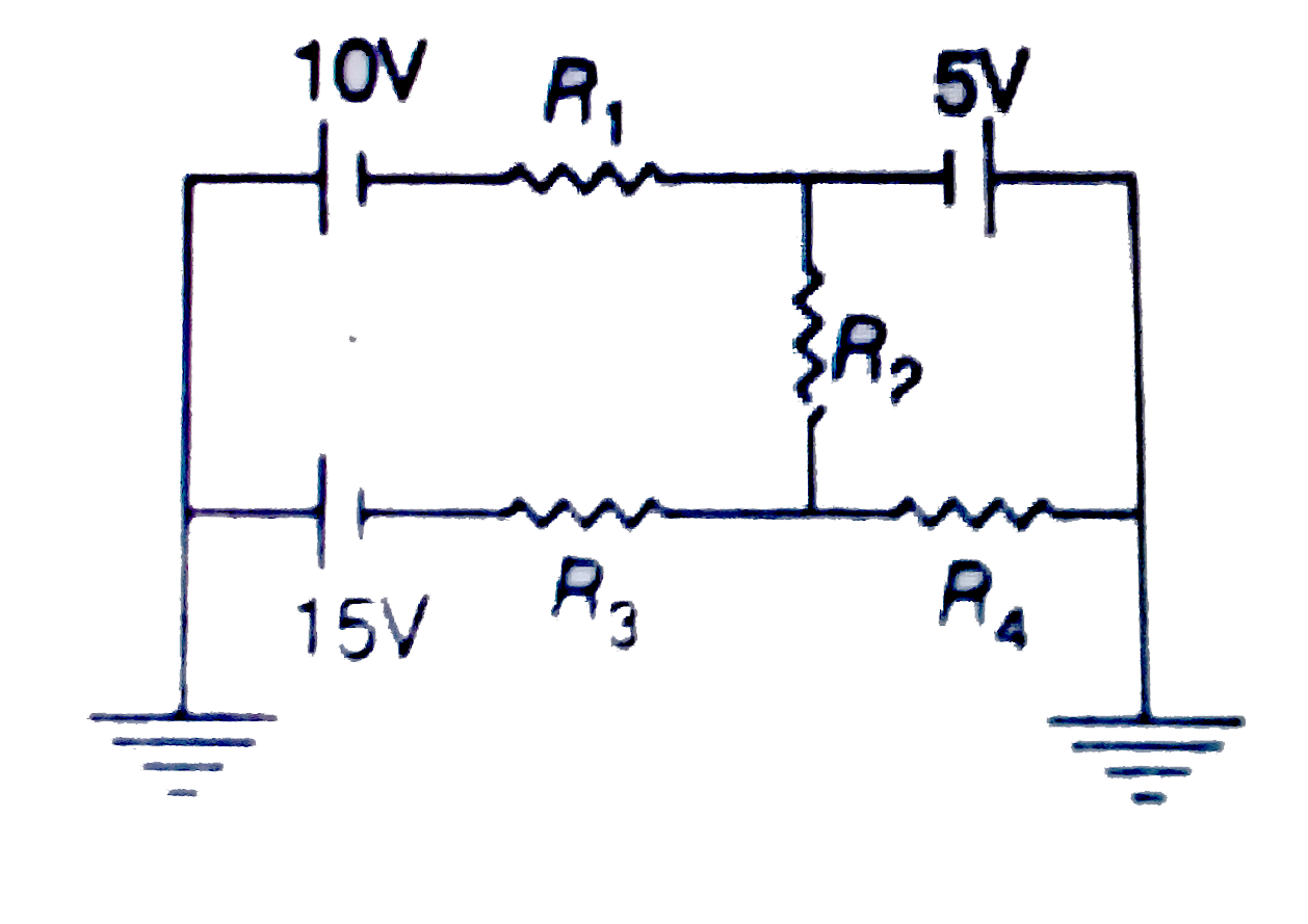
For what ratio R2R4, current through R3 will be zero
View Solution

