Draw an OR gate using two diode and explain its operation. Write the truth table and logic symbol of OR gate.
OR Gate It has two input terminals and one output terminal.If both inputs are low the output is low. If one of the inputs is high, or both the inputs are high then the output of thegate is high.The truth tables of OR gate.
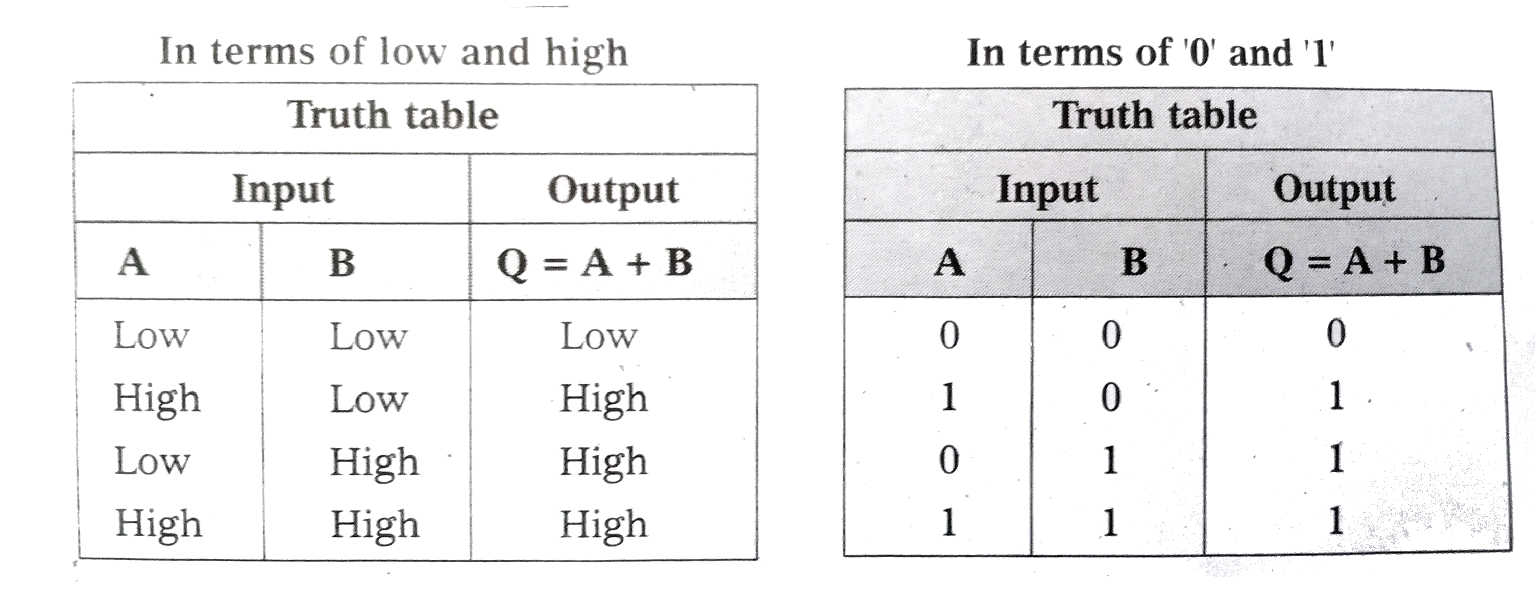
In truth table logic function is written as A or B 'OR' logic function is represented by the symbol 'plus'
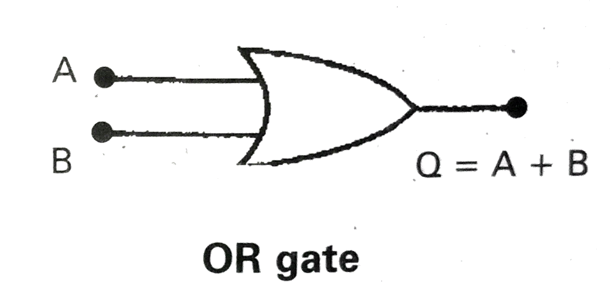
Logic gate 'OR' is shown given below .
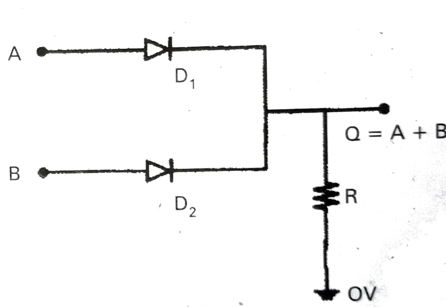
Implementation of OR gate using diode
Let and be two diodes.
A potential of 5V represents the logical value 1 A potential of 0V representes the logical value 0.
When A=,B=0 both the diodes are reverse biased and there is no current through the resistance .So, the potential at Q is zero i.e., Q = 0 . When A=0 or B =0 and the other equal to a potential of 5V the diode whose anode is at a potential of 5V is forward-biased and that diode behaves like a closed switch. The output potential then becomes 5V i.e., Q =1.When both A and B are 1, both the diodes are forward -biased and the potential at Q is same as that at A and Bwhcih is 5V i.e., Q =1 . The output is same as that of the OR gate.
Topper's Solved these Questions
- SEMICONDUCTOR ELECTRONICS : MATERIALS , DEVICES , AND SIMPLE CIRCUITS BOOK - VIKRAM PUBLICATION ( ANDHRA PUBLICATION)CHAPTER - SEMICONDUCTOR ELECTRONICS : MATERIALS , DEVICES , AND SIMPLE CIRCUITS EXERCISE - TEXTUAL EXERCISES
11 Videos
- SEMICONDUCTOR ELECTRONICS : MATERIALS , DEVICES , AND SIMPLE CIRCUITS BOOK - VIKRAM PUBLICATION ( ANDHRA PUBLICATION)CHAPTER - SEMICONDUCTOR ELECTRONICS : MATERIALS , DEVICES , AND SIMPLE CIRCUITS EXERCISE - ADDITIONAL EXERCISES
8 Videos
- SEMICONDUCTOR ELECTRONICS : MATERIALS , DEVICES , AND SIMPLE CIRCUITS BOOK - VIKRAM PUBLICATION ( ANDHRA PUBLICATION)CHAPTER - SEMICONDUCTOR ELECTRONICS : MATERIALS , DEVICES , AND SIMPLE CIRCUITS EXERCISE - SHORT ANSWER QUESTIONS
16 Videos
- RAY OPTICAL AND INSTRUMENTSBOOK - VIKRAM PUBLICATION ( ANDHRA PUBLICATION)CHAPTER - RAY OPTICAL AND INSTRUMENTSEXERCISE - TEXTUAL EXERCISES
60 Videos
- TELANGANA MARCH-2019BOOK - VIKRAM PUBLICATION ( ANDHRA PUBLICATION)CHAPTER - TELANGANA MARCH-2019EXERCISE - SECTION -B
5 Videos
Similar Questions
Draw the symbol and truth table of OR gate.
View SolutionYou are given a circuit below write its truth table hence identify the logic operation carried out by the circuit draw the logic symbol of the gate it corresponds to

View SolutionThe Fig shown input waveforms A and B to a logic gate. Draw the output waveform for an OR gate. Write the truth table for this logic gate and draw its logic symbol.
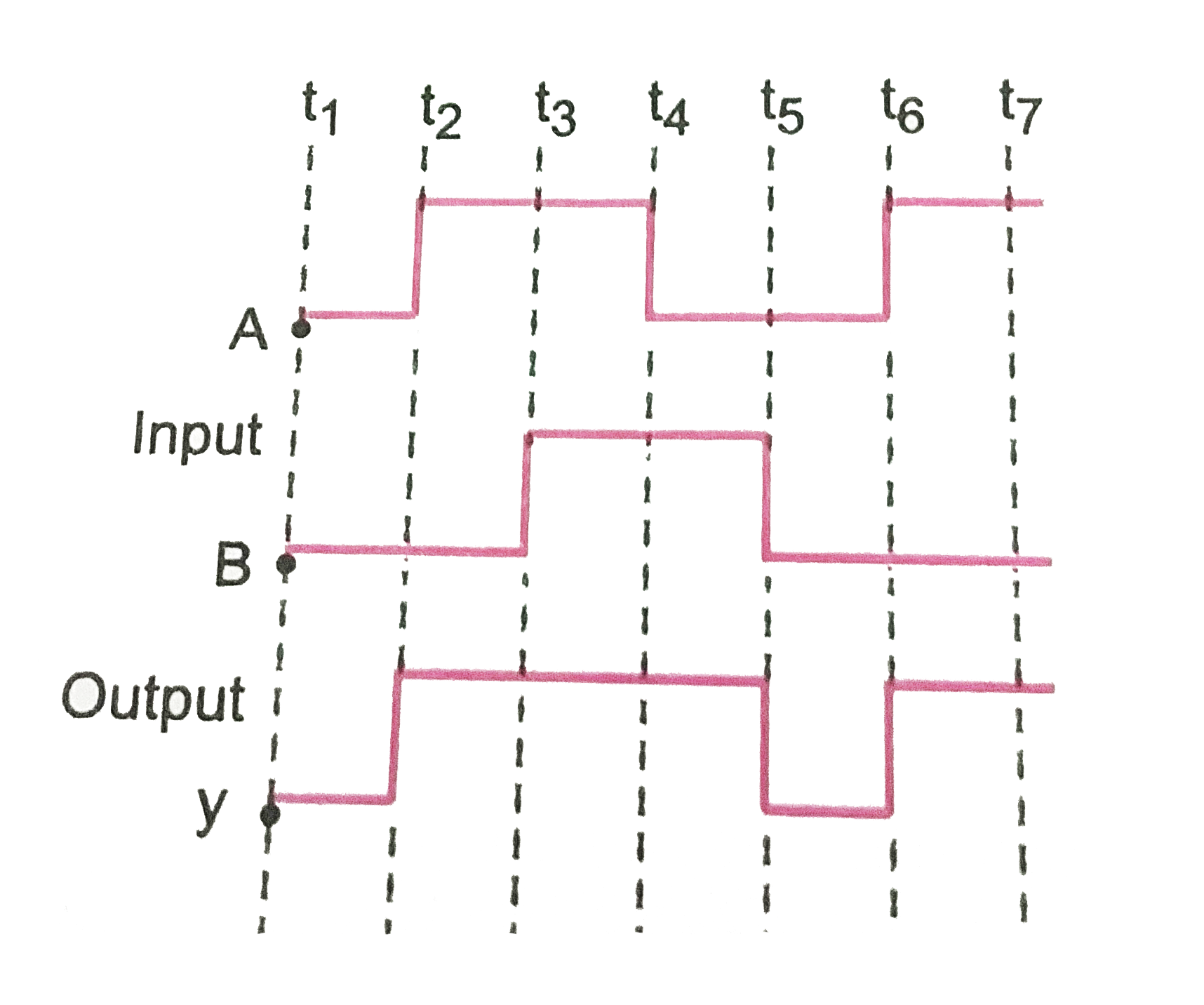
View SolutionThe Fig shown input waveforms A and B to a logic gate. Draw the output waveform for an OR gate. Write the truth table for this logic gate and draw its logic symbol.

View Solution
Name of gate obtained from the combination of gates shown in the figure. Draw its logic symbol. Write the truth table of the combination.
View SolutionDraw the symbol for AND gate and write its truth table.

View Solution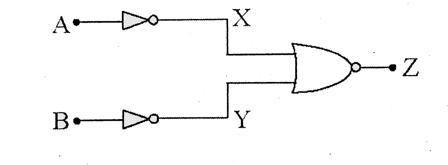
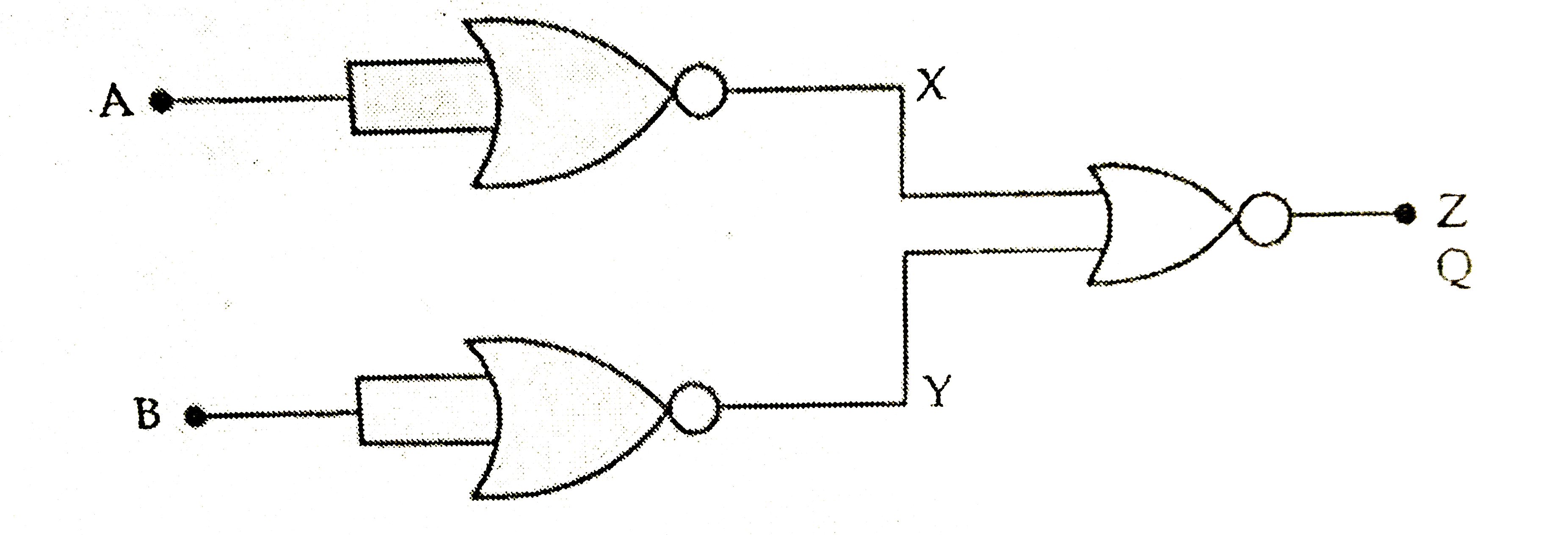
You are given a circuit below. Write its truth table. Hence, identify the logic operation carried out by this circuit. Draw the logic symbol of the gate it corresponds to.
View SolutionYou are given a circuit below. Write its truth table. Hence, identify the logic operation carried out by this circuit. Draw the logic symbol of the gate it corresponds to.
View SolutionYou are given a circuit below. Write its truth table. Hence, identify the logic operation carried out by this circuit. Draw the logic symbol of the gate it corresponds to.

View Solution
You are given a circuit below. Write its truth table. Hence, identify the logic operation carried out by this circuit. Draw the logic symbol of the gate it corresponds to.
View Solution
