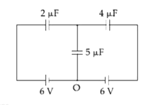
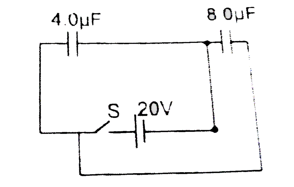
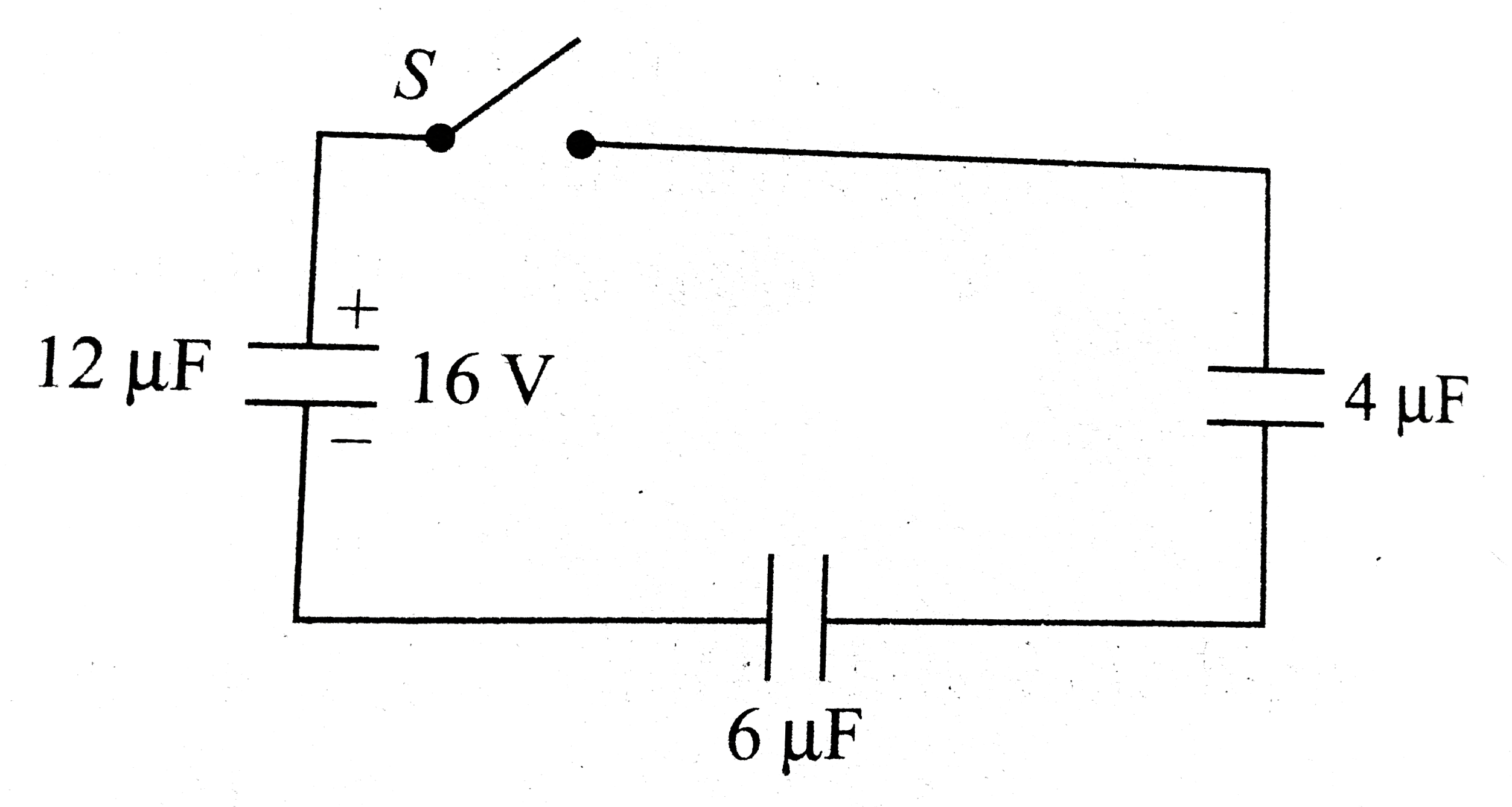
In the arrangement shown in in the switch S is , find
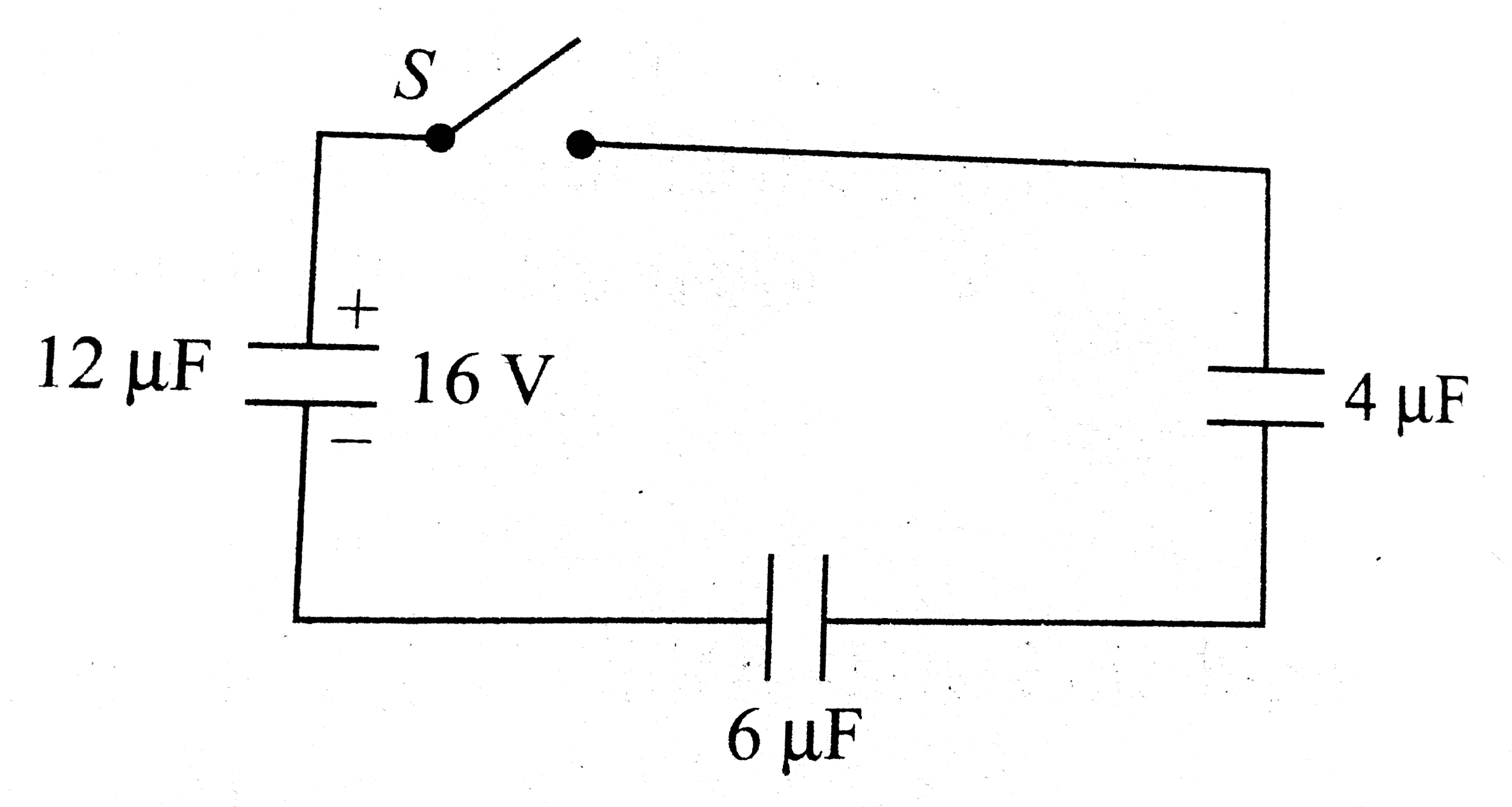
the final charge on the 6μF capacitor
12μC
24μC
32μC
48μc
The correct Answer is:C
In the close loop,
q0−ΔqC1−ΔqC2−ΔqC2=0
 .
.
q0C1=Δq[1C1+1C2+1C3]
Δq=q0C1[1C1+1C2+1C3]=192[1+3+2)=32μC
Potential defferece across C1=ΔqC2=8V
Potential defferece across C1=(192−32)12=16012=403V.
Topper's Solved these Questions
- CAPACITOR AND CAPACITANCEBOOK - CENGAGE PHYSICSCHAPTER - CAPACITOR AND CAPACITANCEEXERCISE - Integer
5 Videos
- CAPACITOR AND CAPACITANCEBOOK - CENGAGE PHYSICSCHAPTER - CAPACITOR AND CAPACITANCEEXERCISE - Multile Correct
11 Videos
- ATOMSBOOK - CENGAGE PHYSICSCHAPTER - ATOMSEXERCISE - QUESTION BANK
40 Videos
- CENGAGE PHYSICS DPPBOOK - CENGAGE PHYSICSCHAPTER - CENGAGE PHYSICS DPPEXERCISE - subjective type
51 Videos
Similar Questions
Knowledge Check
In the arrangement shown in , the switch S is find
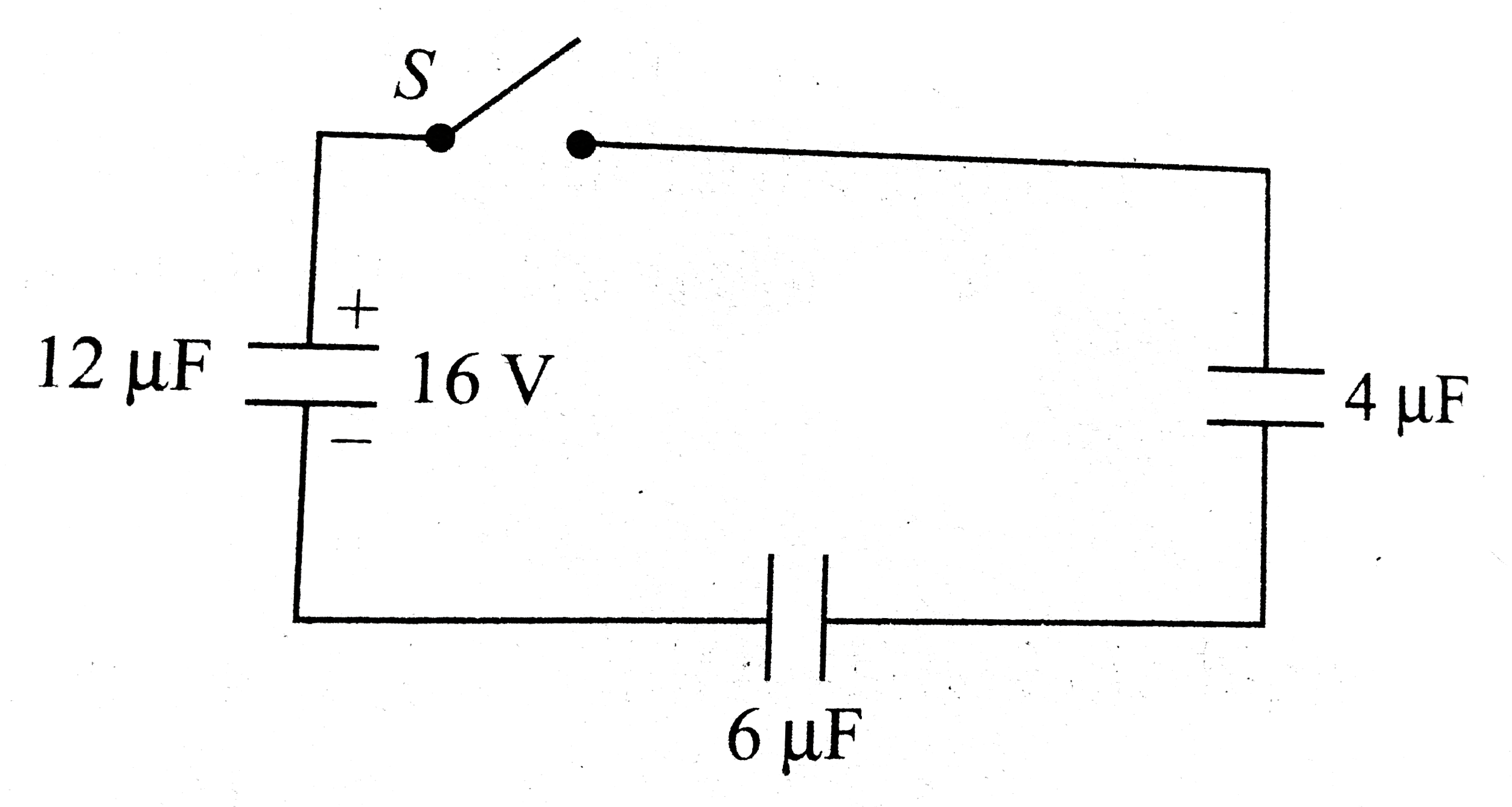 the final potential difference across the 4μF capacitorA12VB8VC20VD32V
In the arrangement shown in, When the switch S is closed, find
 .
.
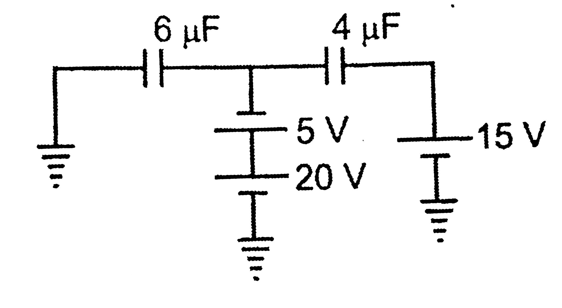
the final potential difference across the 12μF capacitor.A403VB203VC12VD24VFor the arrangement shown in the figure, the charge on the 4μF capacitor is
 A90μCB60μCC36μCDZero
For the arrangement shown in the figure, the switch is closed at t=0. C2 is initially uncharged while C1 has a charge of 2μC
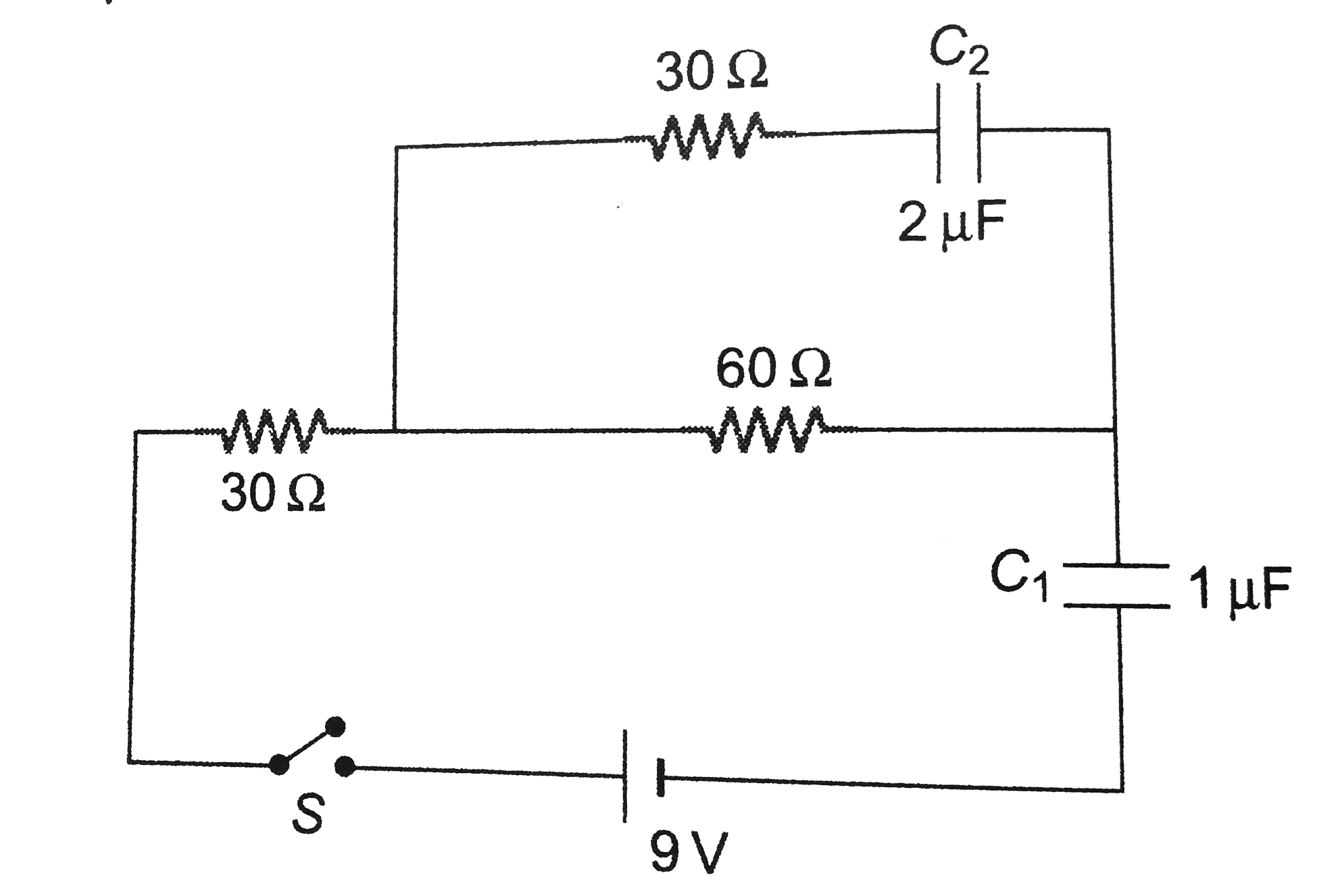
(a) Find the current comingn out of the battery just after the switch is closed.
(b) Find the charge on the capacitors in the steady state condition.
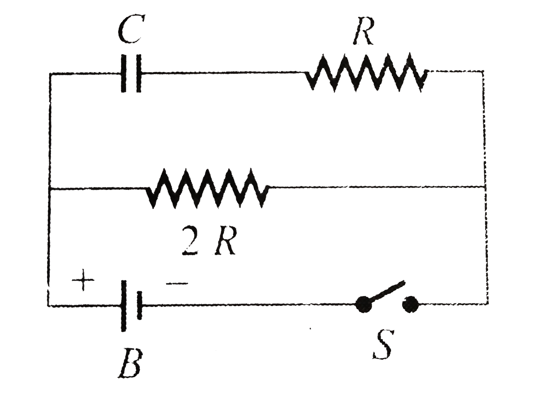
View SolutionIn the circuit shown in fig, if the switch S is closed at t=0 , the capacitor charges with a time constant
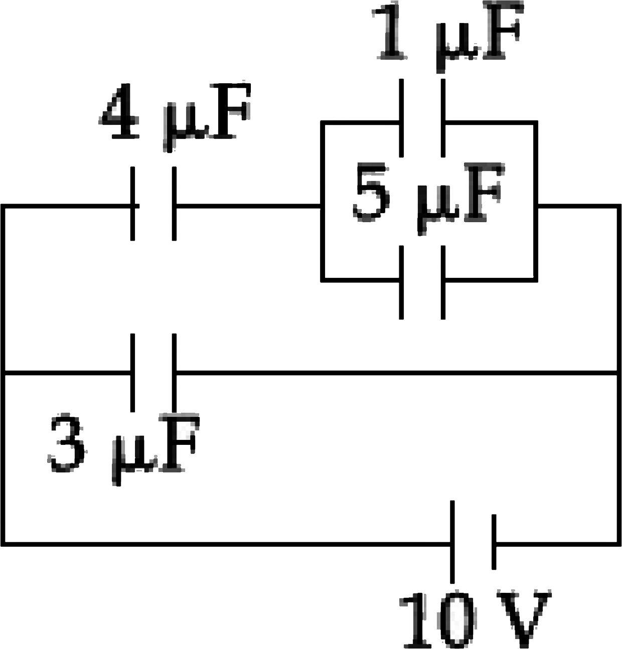
View SolutionIn the given circuit, the charge on 4μF capacitor will be :
 .
.
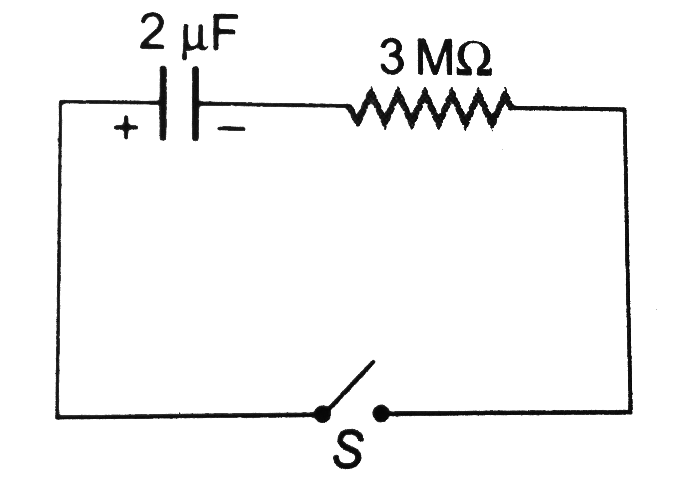
View SolutionIn the circuit shown in figure, the capacitor is charged with a cell of 5V.If the switch is closed at t=0, then at t=12s, charge on the capacitor is
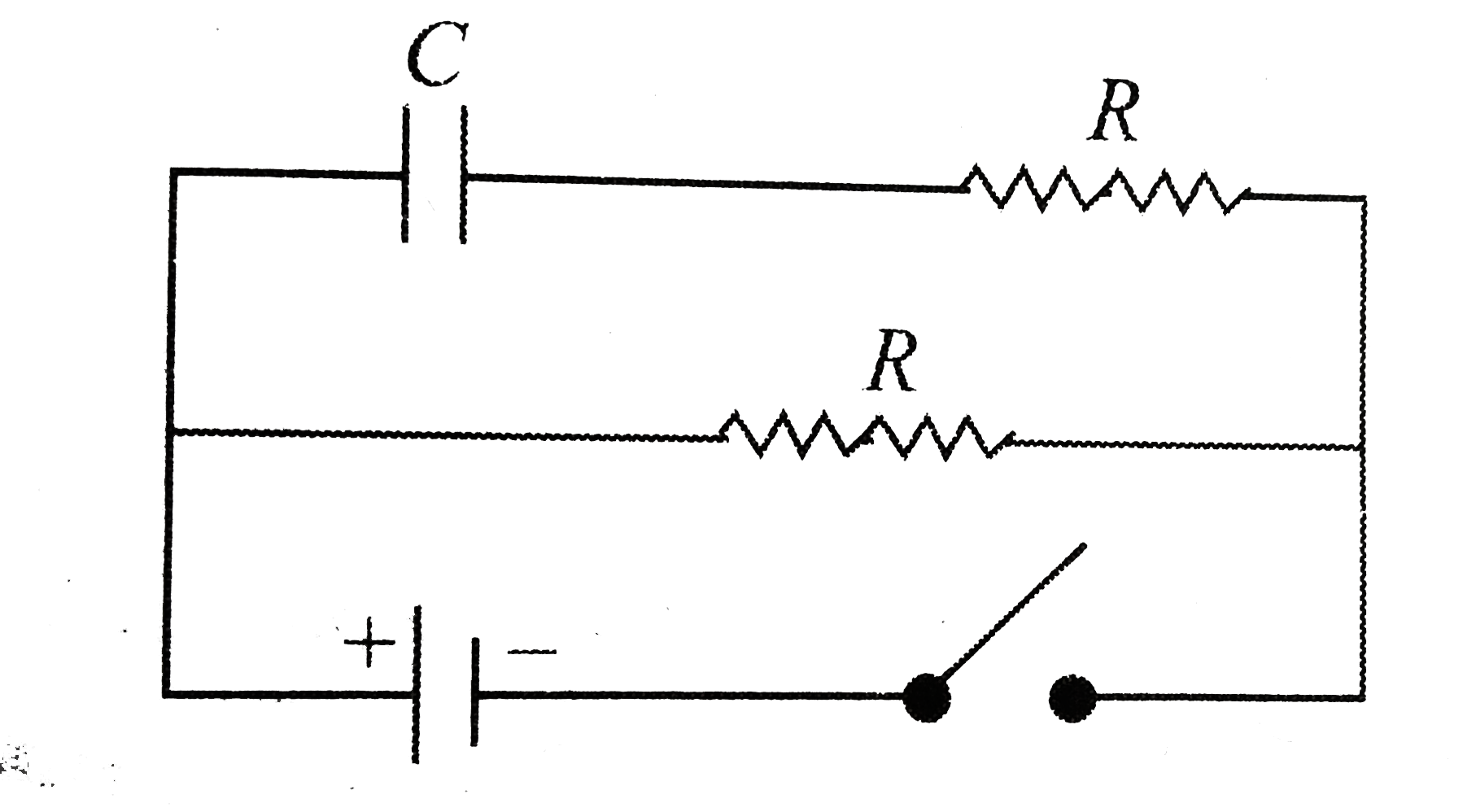
View SolutionIn the circuit shown in fig. when the switch is closed, the capacitor charges with a time constant
View Solution

