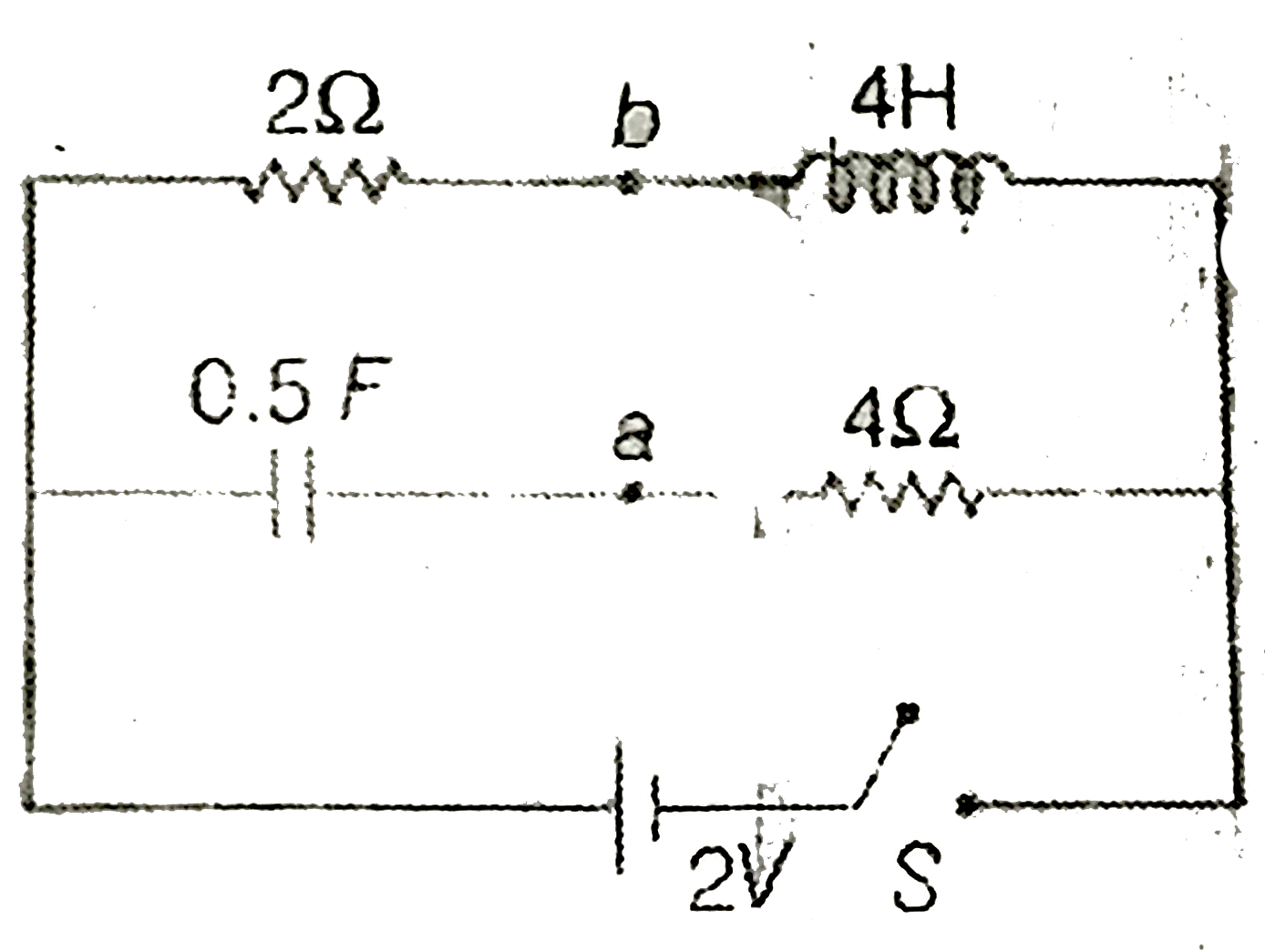
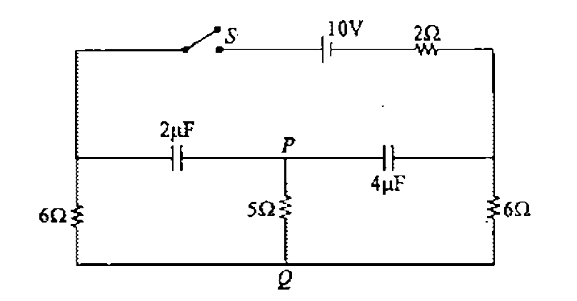
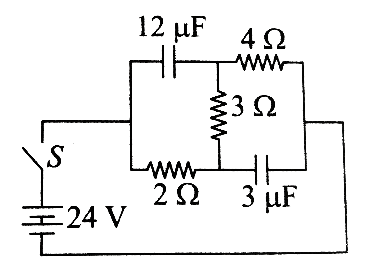
The following two questions refer to the circuit shown. Assume that the capacitors are initially uncharged.
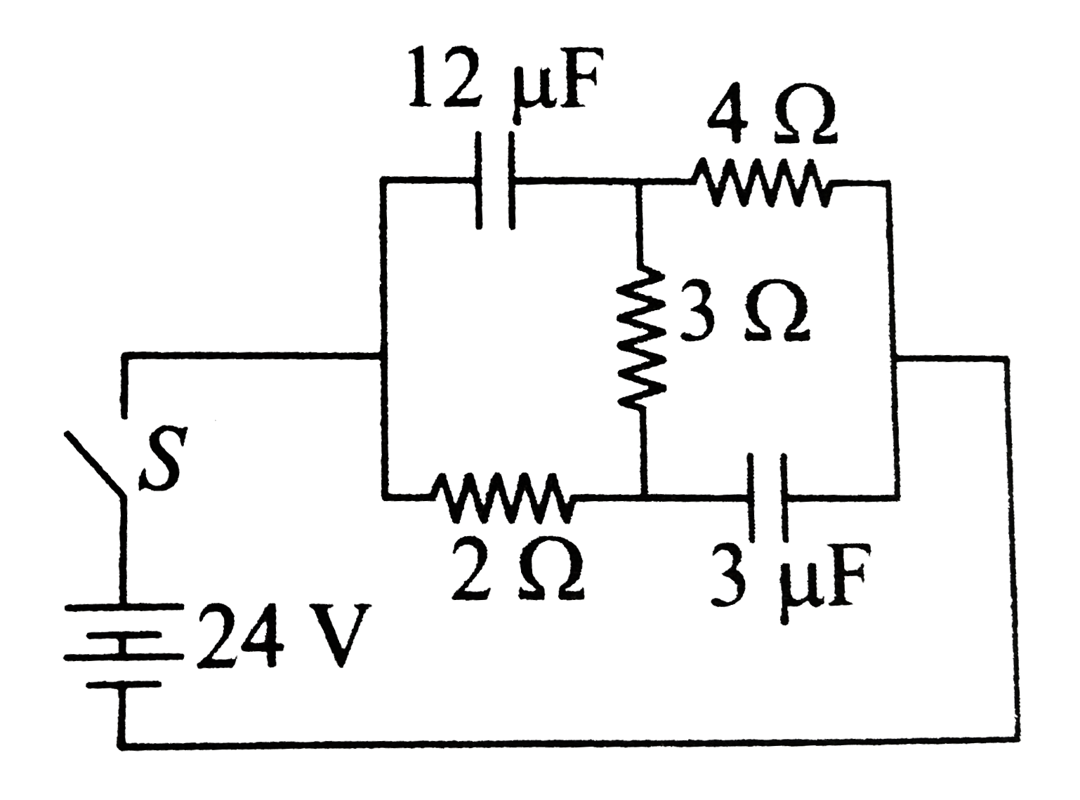
After the switch has been closed for a long time, how much charge is on the positive plate of the 3μF capacitor?
24μC
32μC
56μC
72μC
The correct Answer is:C
Initially capacitors act as conducting wire. So initially all the three resistor will be in parallel.
After long time, resistors will be in series,
Req=2+3+4=9Ω
I=249=83A
Potential difference 3μF= potential difference across (3Ω+4Ω)
⇒V3μF=(3+4)I=563v
q=CV3μF=3×563=56μC
Topper's Solved these Questions
- ELECTRIC CURRENT AND CIRCUITBook:CENGAGE PHYSICSChapter:ELECTRIC CURRENT AND CIRCUITExercise:Interger
Explore 8 Videos
- ELECTRIC CURRENT AND CIRCUITBook:CENGAGE PHYSICSChapter:ELECTRIC CURRENT AND CIRCUITExercise:Multiple Correct
Explore 16 Videos
- ELECTRIC CURRENT & CIRCUITSBook:CENGAGE PHYSICSChapter:ELECTRIC CURRENT & CIRCUITSExercise:Kirchhoff s law and simple circuits
Explore 15 Videos
- ELECTRIC FLUX AND GAUSS LAWBook:CENGAGE PHYSICSChapter:ELECTRIC FLUX AND GAUSS LAWExercise:MCQ s
Explore 38 Videos
Similar Questions
Knowledge Check
In the circuit shown key is closed at t=0 with capacitor initially uncharged.
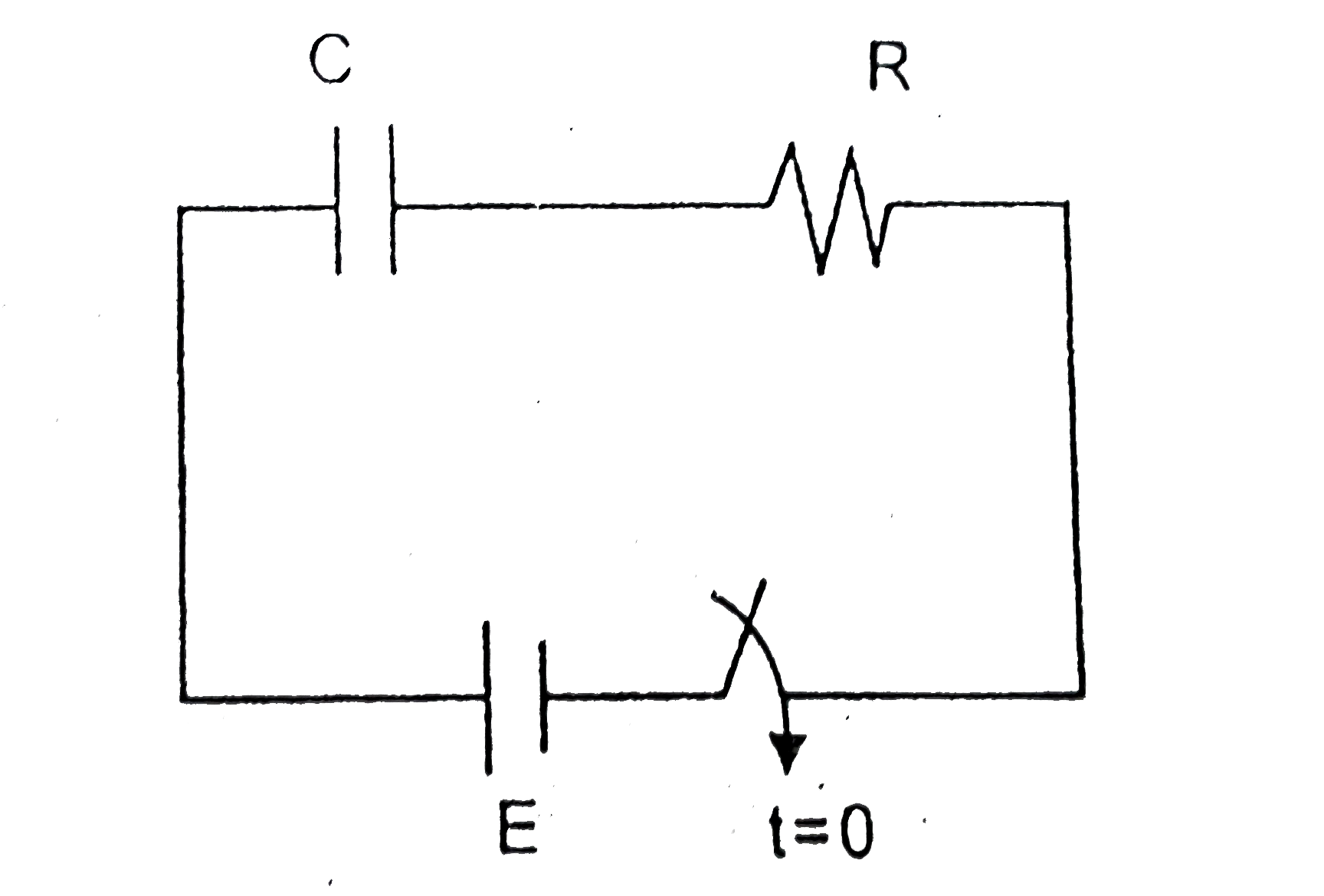 ARate of increase of capacitors energy, just after the switch is closed is E2RBMaximum power supplied by the cell is E2RCAt t=RCIn2, capacitor is charged up to half of the energy stored by it in steady stateDAt t=RCIn2, potential difference across capacitor is same that across resistor.
The following two questions refer to the circuit shown. Assume that the capacitors are initially uncharged.
At time t = 0, the switch S in the circuit is closed. At that instant, what is the equivalent resistance of the circuit?A9.00B1.20C1.80D0.92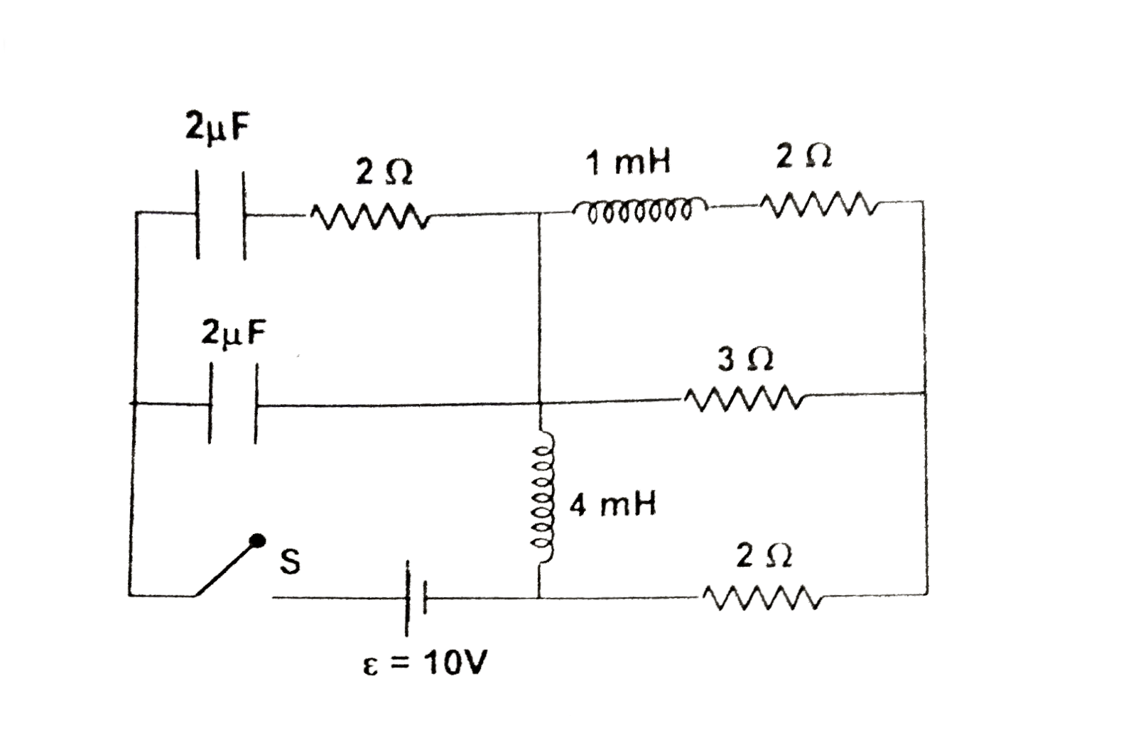
In the circuit shown, all the capacitors are initially uncharged. The current through the battery just after closing the switch 'S' isA2AB4AC5AD10A
The current through the battery just after the switch S is Closed is (the capacitors are initially uncharged )
_PHY_E01_002_Q01.png)
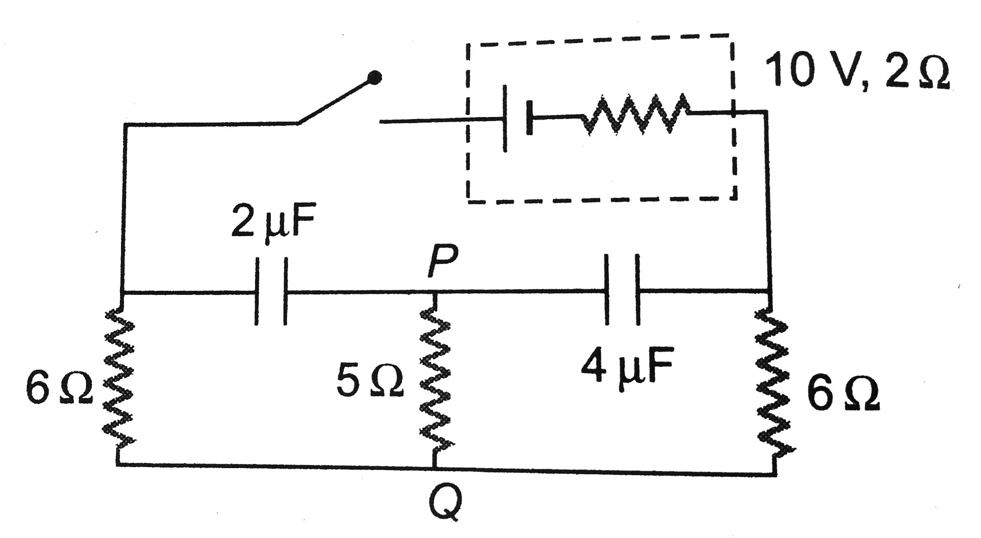
View SolutionIn the circuit shown in figure, the capacitors are initially uncharged. The current through resistor PQ just after closing the switch is
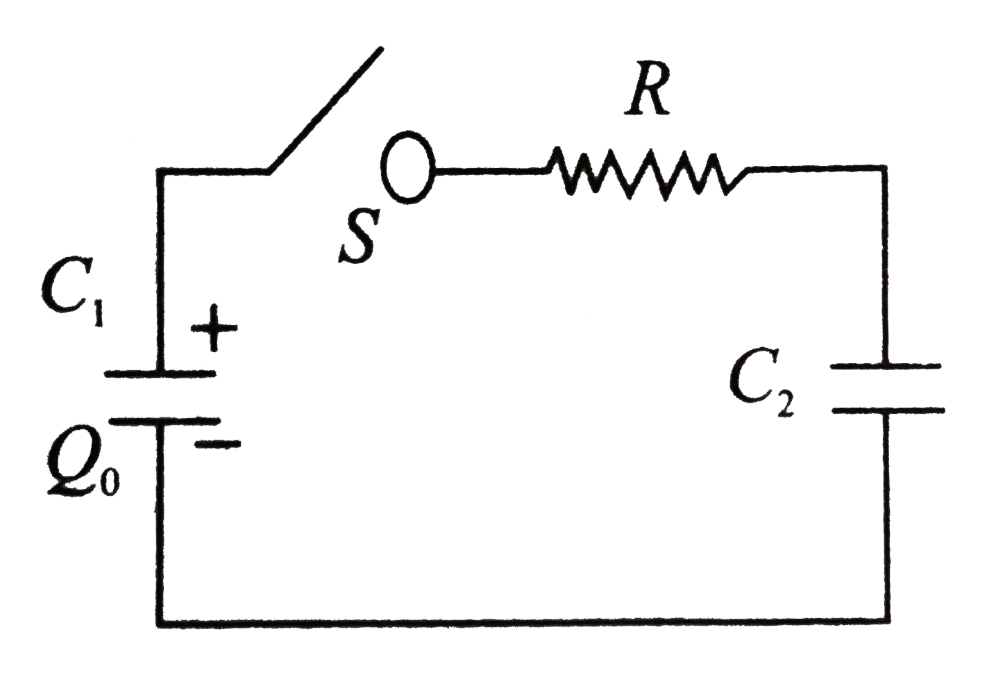
View SolutionIn the circuit shown, the capacitor C1 is initially charged with charge q0. The switch S is closed at time t = 0 . The charge on C2 after time t is
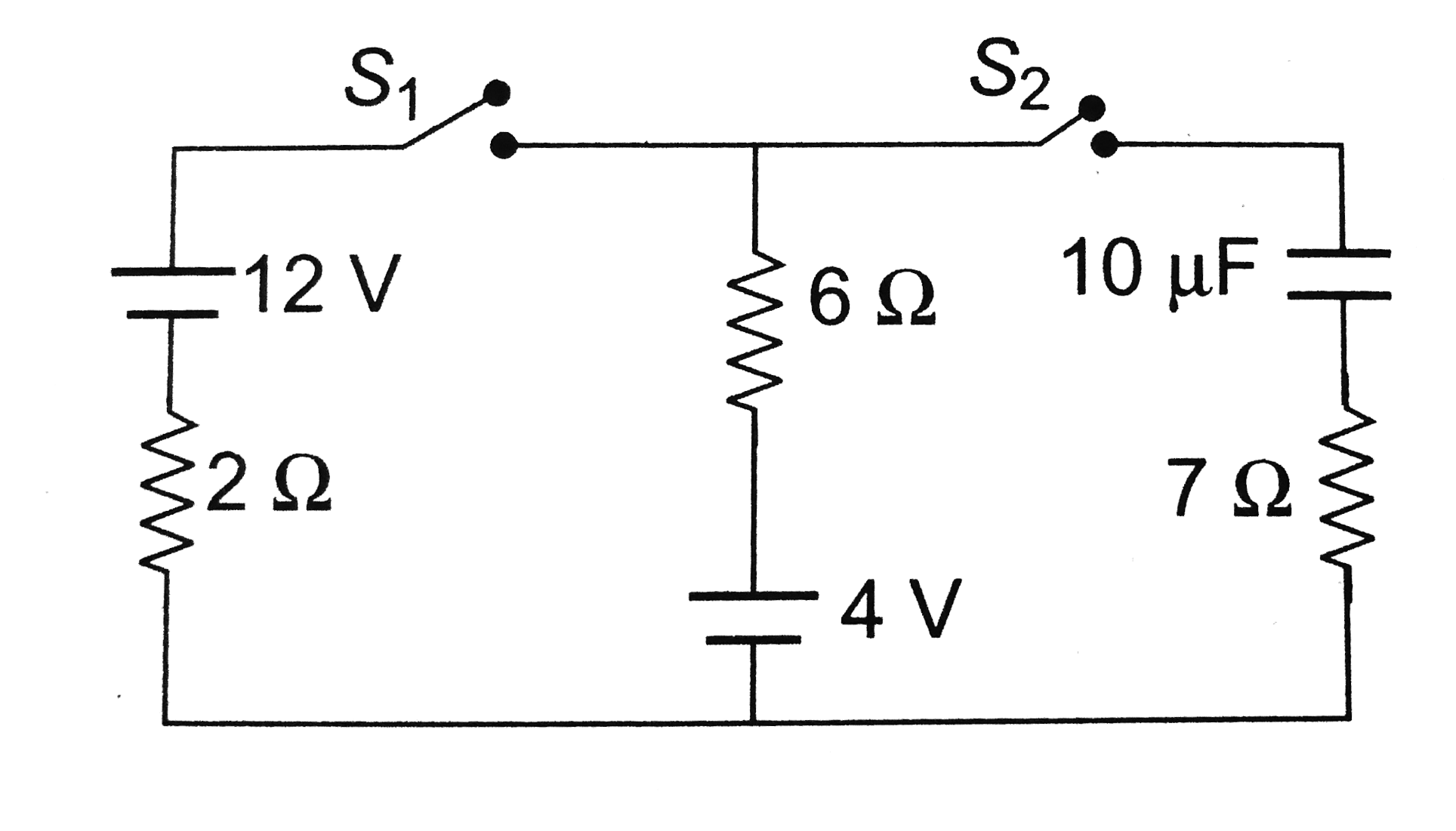
View SolutionIn the circuit shown in the figure, if switches S1 and S2 have been closed for a long time, then charge on the capacitor.
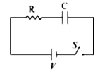
View SolutionIn the circuit shown, the capacitor is initially uncharged. The switch S is closed at t = 0. Time after which voltage across capacitor and resistor are equal is:
View Solution
