Figure 3.15(a) shown two circular rings of radii a and b (a>b) joined together with wires of negligible resistance. Figure 3.15(b) shown thew pattern obtained by folding the small loop in the plane of the large loop.
(a) 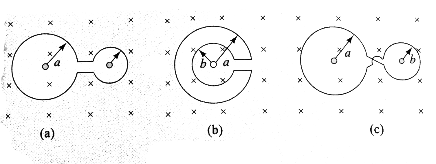
The pattern shown in Fig.3.15( c ) is obtained by twisting the small loop of Fig.3.15(a) through 180∘.
All the three arrangement are placed in a uniform time varying magnetic field dB/dt=k, perpendicular to the plane of the loops. if the resistance per unit length of the wire is λ, then determine the induced current in each case.
(a) ϕB=π(a2+b2)B
ε=dϕdt=π(a2+b2)×dBdt=π(a2+b2)k
Induced current, I=εR=π(a2+b2)kλ[2λ(a+b)]=k(a2+b2)2λ(a+b)
(b) ϕB=πa2B−πb2B=πB(a2−b2)
ε=dϕBdt=πdBdt×(a2−b2)=πk(a2−b2)
Induced current, I=εR=πk(a2−b2)2πλ(a+b)=k(a−b)2λ
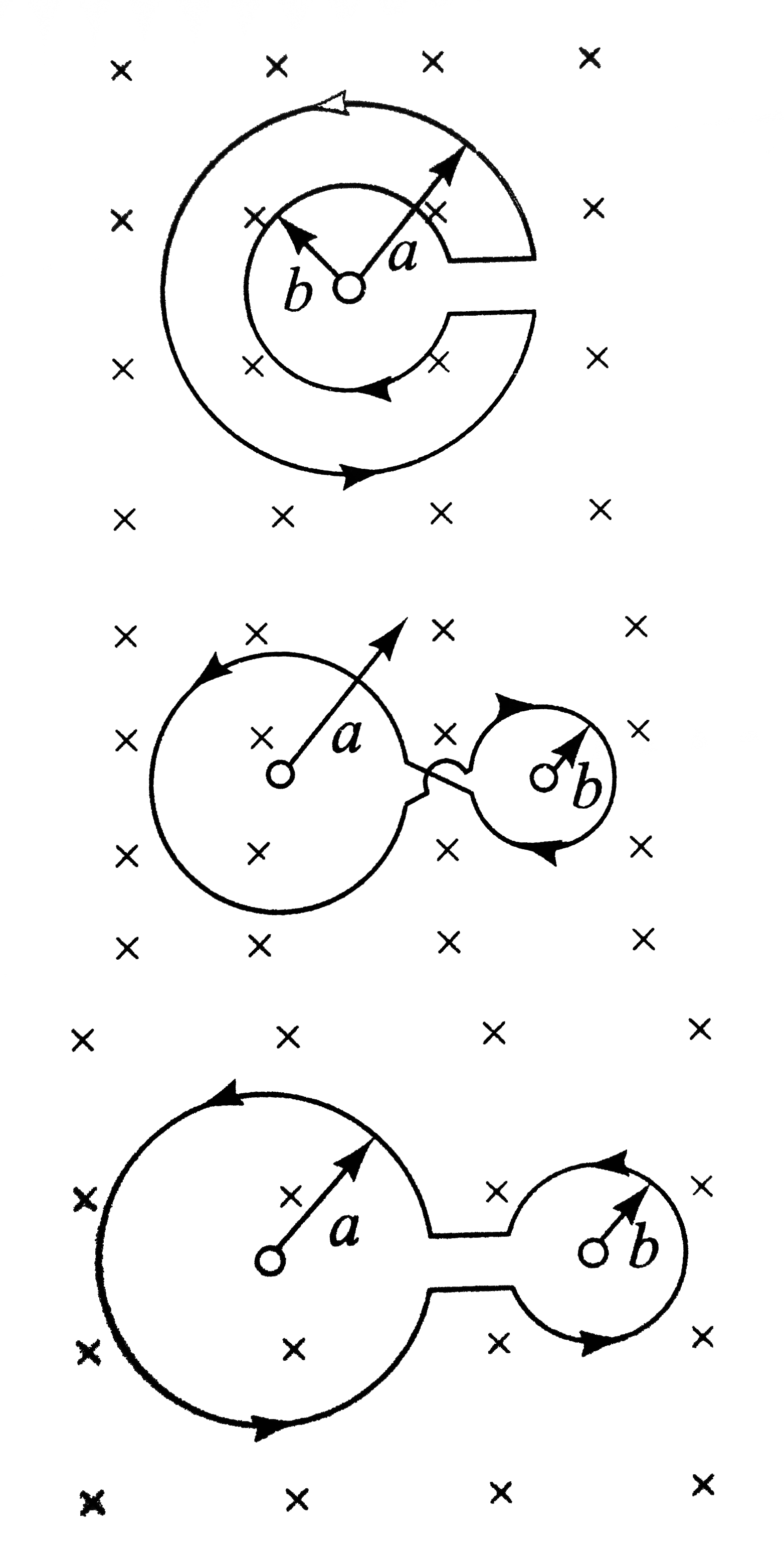


( c) Here induced emf in both loops will oppose each other, hence effective flux is given by
ΦB=πa2B−πb2B=πB(a2−b2)
→ ε=dΦBdt=πk(a2−b2)
induced current, I=εR=k(a−b)2λ
Topper's Solved these Questions
- BOOK - CENGAGE PHYSICSCHAPTER - ELECTROMAGNETIC INDUCTIONEXERCISE - Solved Example5videos
ELECTROMAGNETIC INDUCTION
- BOOK - CENGAGE PHYSICSCHAPTER - ELECTROMAGNETIC INDUCTIONEXERCISE - Exercise 3.115videos
ELECTROMAGNETIC INDUCTION
- BOOK - CENGAGE PHYSICSCHAPTER - ELECTROMAGENTIC INDUCTIONEXERCISE - QUESTION BANK40videos
ELECTROMAGENTIC INDUCTION
- BOOK - CENGAGE PHYSICSCHAPTER - ELECTRON,PHONTS,PHOTOELECTRIC EFFECT & X-RAYSEXERCISE - dpp 3.315videos
ELECTRON,PHONTS,PHOTOELECTRIC EFFECT & X-RAYS
Similar Questions
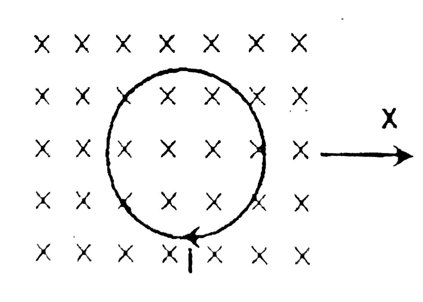
A circular loop of wire is carring a current i (as shown in the figure). On applying a uniform magnetic field inward perpendicular to the plane of the loop, the loop
 View Solution
A plane loop is shaped ion the from as shown in the figure with radii a and b and is placed in a uniform time varying magnetic field B=B0sinωt . Find the amplitude of the current induced in the loop if its resistance per unit length is equal to λ . The inductance of the loop negligible.
 View Solution
Knowledge Check
- Question 1 - Select One
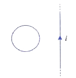
A loop and an infinite wire are placed side by side as shown in the figure. If the current I in the wire is increased then the induced current in the loop is
 AclockwiseBanticlockwiseCzeroDcannot determine
 - Question 2 - Select One
In a closed loop, which has some inductance but negligible resistance, uniform but time varying magentic field is applied directed into the plane of the loop. Variation of field with time is shown in Fig. Initially current in loop was zero. Then .
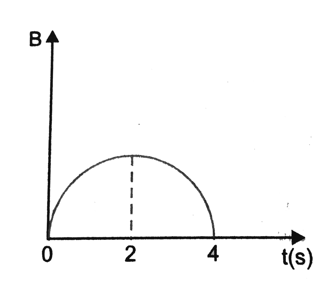 Aemf induced in the loop is zero at t=2sBcurrent in the loop will be maximum at t=2sCdireciton of emf in the loop will not change at t=2sDnone of above
 - Question 3 - Select One
The current flows from A to B as shown in the figure The direction of the induced current in the loop is :
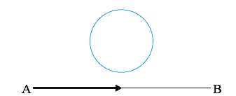 AclockwiseBanticlockwiseCstraight lineDnone of these
A closed loop with the geometry shown in Fig. 3.9 is placed in a uniform magnetic field direction into the plane of the paper. If the magnetic field decreases with time, determine the direction of the induced emf in this loop.
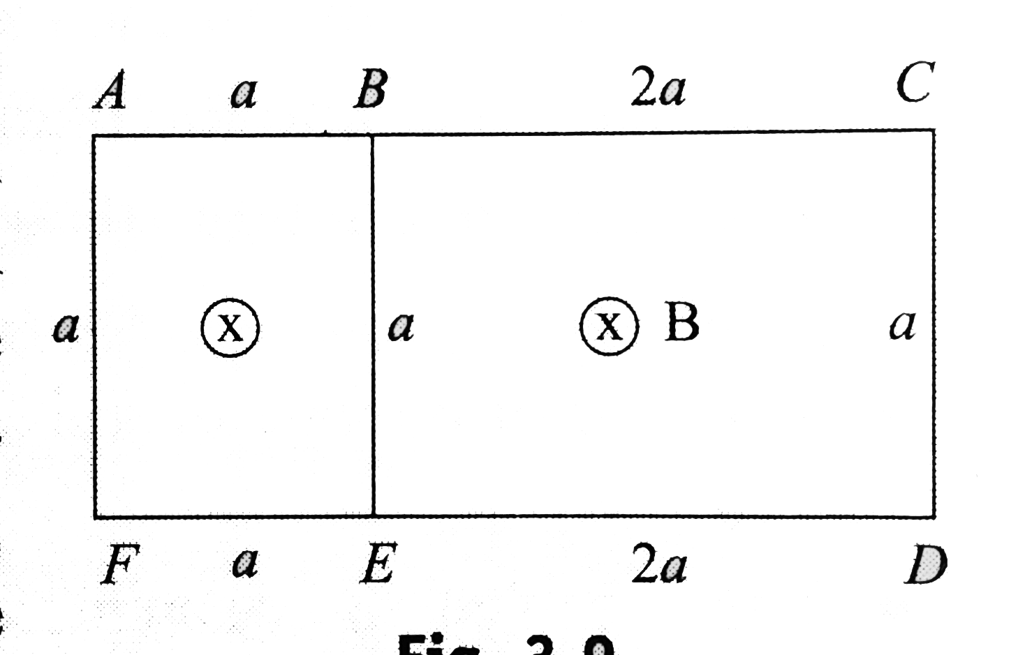 View Solution
Find the mutual inductance between the circular coil and the loop shown in figure.
View SolutionFind the magnetic field at the centre of the circular loop shown in figure.
 View Solution
Find the magnetic field at the centre of the circular loop shown in figure.
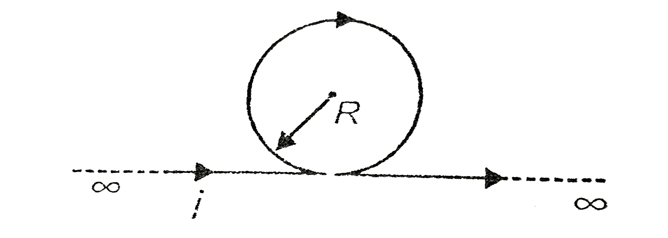 View Solution
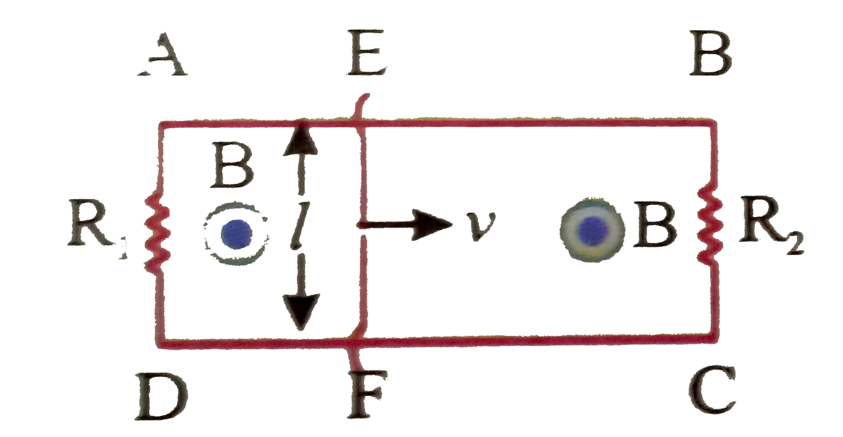
A loop ABCD containing two resistors as shown in figure is placed in a uniform magnetic fielf B directed outwards to the plane of page. A sliding conductor EF of length l and of negligible resistance moves to th right with a uniform velocity v as shown in Fig. Determine the current in each branch.
 View Solution
