In the circuit shown in Fig. the capacitor has capacitance C=20μF and is initially charged to 100V with the polarity shown. The resistor R0 has resistance 10Ω. At time t=0, the switch is closed. The smaller circuit is not connected in any way to teh larger one. the wire of the smaller circuit has a resistance of 1.0Ωm−1 and contains 25 loops. the larger circuit is a rectangle 2.0m by 4.0m, while the smaller one has dimensions a=10.0cm and b=20.0cm. the distance cis 5.0cm. (The figure is not drawn to scale.) Both circuit are held stationary. Assume that only the wire nearest to teh smaller circuit produces. an appreciable magnetic field through it.
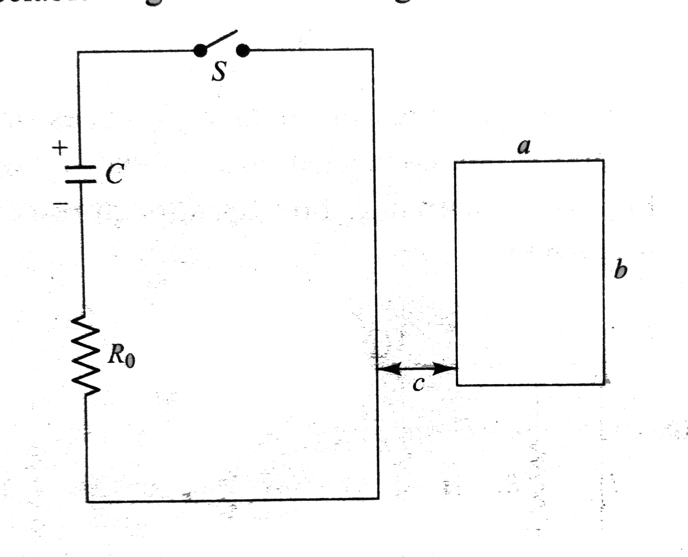
The direction of current in the smaller circuit is
(a) clockwise
(b) anticlockwise
( c) always changes with time
(d) cannot be calculated
The correct Answer is:B
(b) The large circiut is a with a time constant of
τ=RC=(10Ω)(20×10−6F)=200μs.
Thus, the currnt as a function of time is
I=(100V10Ω)e−t200μs
At t=200ms, we obtain
I=(10A)(e−1)=3.7A.
Assuming that only the long wire nearest the small loop produces an appreciable magnetic flux through the small loop,
ΦB=∫c+acμ0ib2πdr=μ0ib2π1n(1+ac) ltbr> So the emf induced in the small loop at t=200ms
ε=−dΦdt=−μ0ib2π1n(1+ac)didt
=−(4π×10−7(Wb)A×m2)(0.200m)2π×1n(3.0)(−3.7A200×10−6s)
Thus, the induced current in the small loop is
i=εR=0.81mV25(0.600m)(1.0Ω/m)=54μA. ltbr> Initially current in large loop is maximum and afterwards decreases. Hence flux through the smaller loop decreases with time. The induced current will act to oppose the decreases in flux from the large loop. Thus, the induced current flows counterclockwise .
Topper's Solved these Questions
- ELECTROMAGNETIC INDUCTIONBOOK - CENGAGE PHYSICSCHAPTER - ELECTROMAGNETIC INDUCTIONEXERCISE - Exercises Integer
9 Videos
- ELECTROMAGNETIC INDUCTIONBOOK - CENGAGE PHYSICSCHAPTER - ELECTROMAGNETIC INDUCTIONEXERCISE - Archives Fill In The Blanks
3 Videos
- ELECTROMAGNETIC INDUCTIONBOOK - CENGAGE PHYSICSCHAPTER - ELECTROMAGNETIC INDUCTIONEXERCISE - Exercises Asserton - Reasoning
8 Videos
- ELECTROMAGENTIC INDUCTIONBOOK - CENGAGE PHYSICSCHAPTER - ELECTROMAGENTIC INDUCTIONEXERCISE - QUESTION BANK
40 Videos
- ELECTRON,PHONTS,PHOTOELECTRIC EFFECT & X-RAYSBOOK - CENGAGE PHYSICSCHAPTER - ELECTRON,PHONTS,PHOTOELECTRIC EFFECT & X-RAYSEXERCISE - dpp 3.3
15 Videos
Similar Questions
In the circuit shown in Fig. the capacitor has capacitance C=20μF and is initially charged to 100V with the polarity shown. The resistor R0 has resistance 10Ω. At time t=0, the switch is closed. The smaller circuit is not connected in any way to teh larger one. the wire of the smaller circuit has a resistance of 1.0Ωm−1 and contains 25 loops. the larger circuit is a rectangle 2.0m by 4.0m, while the smaller one has dimensions a=10.0cm and b=20.0cm. the distance cis 5.0cm. (The figure is not drawn to scale.) Both circuit are held stationary. Assume that only the wire nearest to teh smaller circuit produces. an appreciable magnetic field through it.
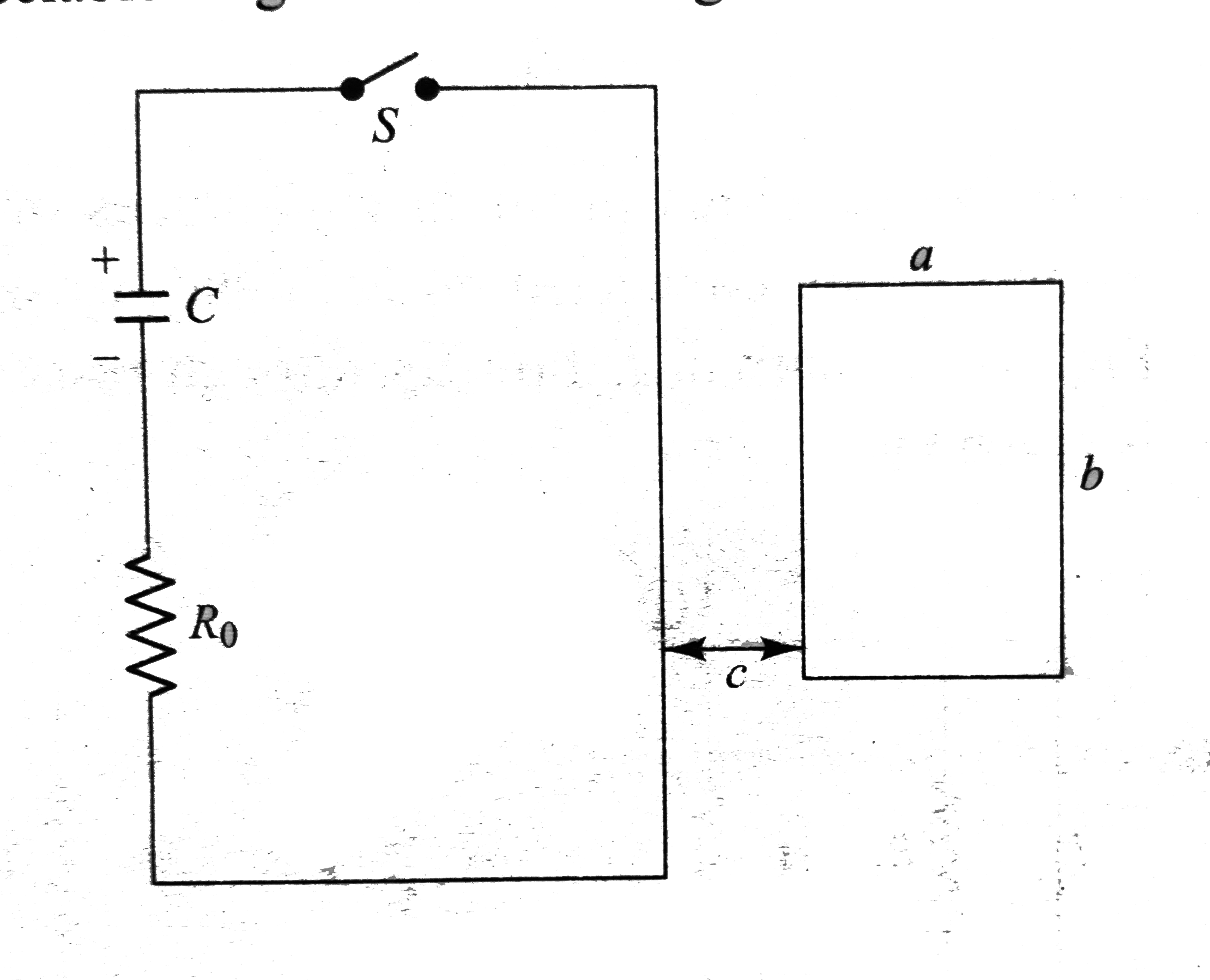
The current in the circuit 200ms after closing S is
View SolutionIn the circuit shown in Fig. the capacitor has capacitance C=20μF and is initially charged to 100V with the polarity shown. The resistor R0 has resistance 10Ω. At time t=0, the switch is closed. The smaller circuit is not connected in any way to teh larger one. the wire of the smaller circuit has a resistance of 1.0Ωm−1 and contains 25 loops. the larger circuit is a rectangle 2.0m by 4.0m, while the smaller one has dimensions a=10.0cm and b=20.0cm. the distance cis 5.0cm. (The figure is not drawn to scale.) Both circuit are held stationary. Assume that only the wire nearest to teh smaller circuit produces. an appreciable magnetic field through it.
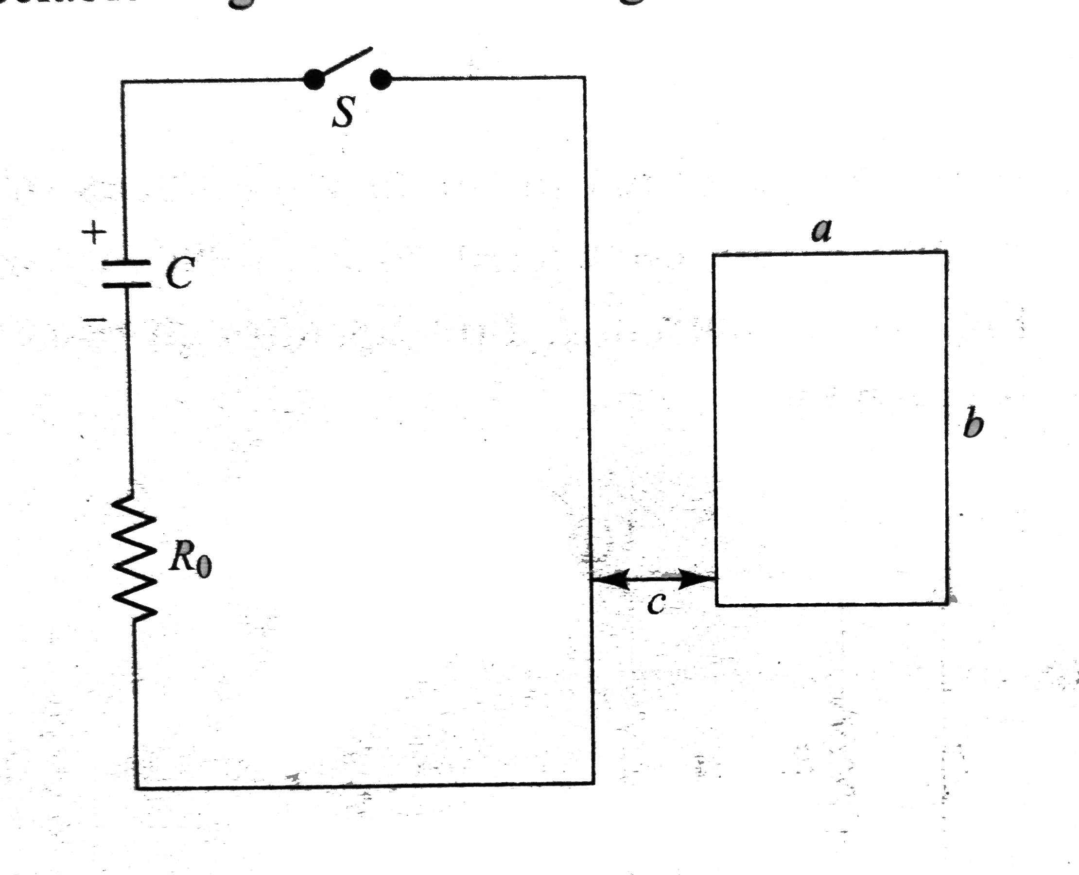
The curent in the smaller circuit 200μs after closing S is
View Solution
Knowledge Check
In the circuit shown in Fig. the capacitor has capacitance C=20μF and is initially charged to 100V with the polarity shown. The resistor R0 has resistance 10Ω. At time t=0, the switch is closed. The smaller circuit is not connected in any way to teh larger one. the wire of the smaller circuit has a resistance of 1.0Ωm−1 and contains 25 loops. the larger circuit is a rectangle 2.0m by 4.0m, while the smaller one has dimensions a=10.0cm and b=20.0cm. the distance cis 5.0cm. (The figure is not drawn to scale.) Both circuit are held stationary. Assume that only the wire nearest to teh smaller circuit produces. an appreciable magnetic field through it.

The current in the circuit 200ms after closing S isA(a) 5eAB(b) 2eAC( c) 15eAD(d) 10eAIn the circuit shown in Fig. the capacitor has capacitance C=20μF and is initially charged to 100V with the polarity shown. The resistor R0 has resistance 10Ω. At time t=0, the switch is closed. The smaller circuit is not connected in any way to teh larger one. the wire of the smaller circuit has a resistance of 1.0Ωm−1 and contains 25 loops. the larger circuit is a rectangle 2.0m by 4.0m, while the smaller one has dimensions a=10.0cm and b=20.0cm. the distance cis 5.0cm. (The figure is not drawn to scale.) Both circuit are held stationary. Assume that only the wire nearest to teh smaller circuit produces. an appreciable magnetic field through it.

The curent in the smaller circuit 200μs after closing S isA(a) 54μAB(b) 10μAC( c) 15μAD(d) 36μAIn the circuit shown in fig. the cell has emf 10V and internal resistance 1Ω
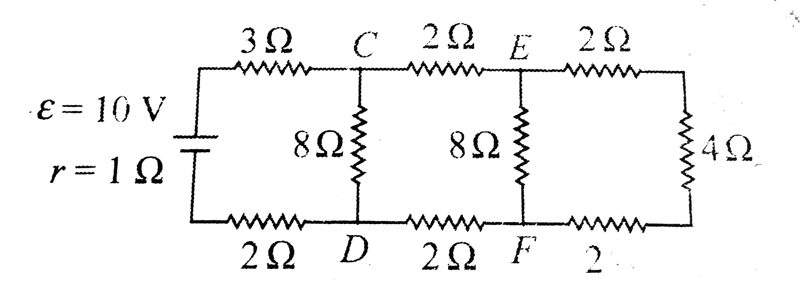 AThe current through the 3Ω resistor is 1A.BThe currents through the 3Ω resistor is 0.5 A.CThe currents through the 4Ω resistor is 0.5 ADThe current through the 4Ω resistor is 0.25 A.
In the circuit shown in fig. the cell has emf 10V and internal resistance 1Ω

View SolutionIn the circuit shown in fig, if the switch S is closed at t=0 , the capacitor charges with a time constant
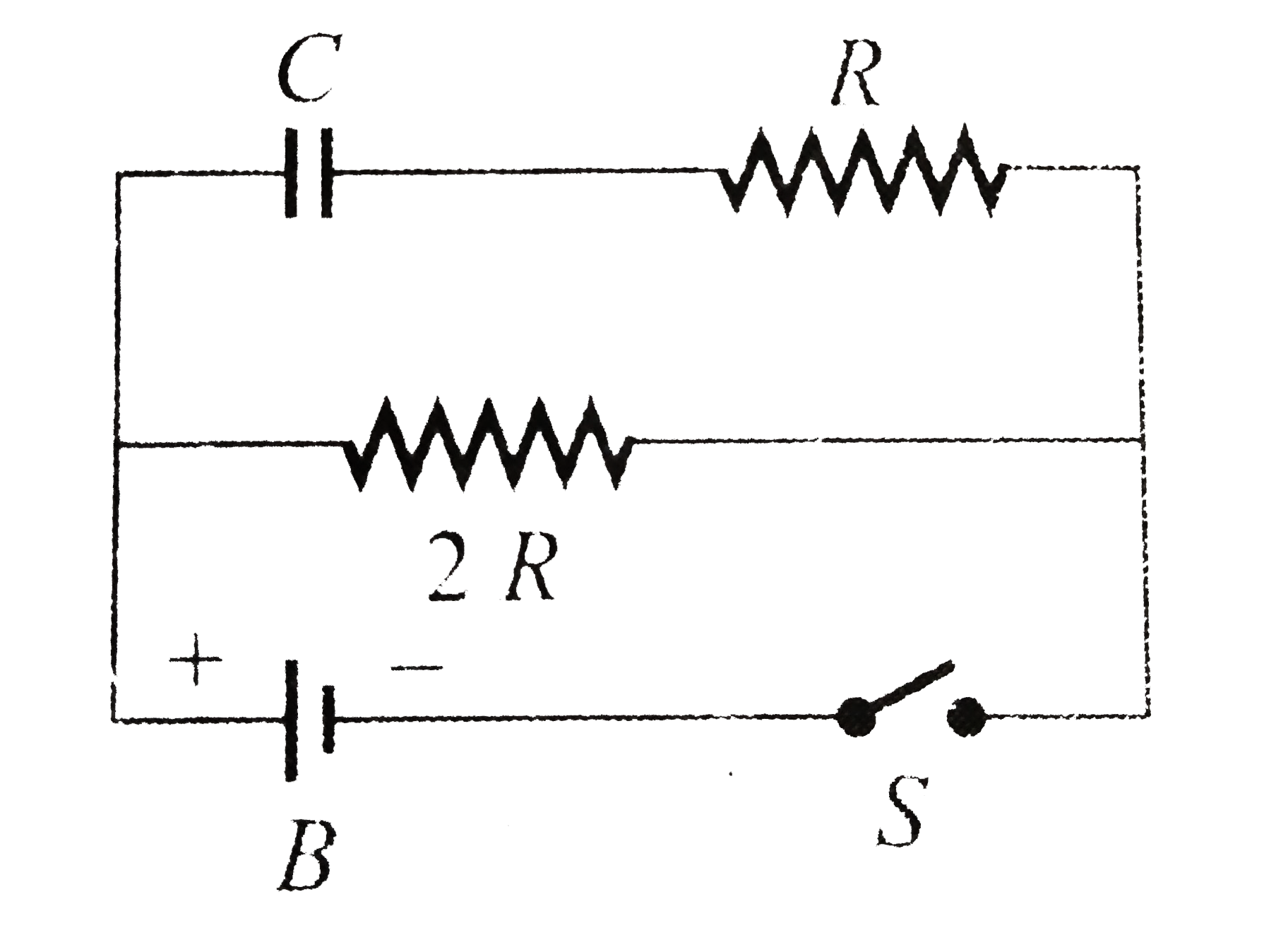
View SolutionThe plates of capacitor of capacitance 10μF, charged to 60μC, are joined together by a wire of resistance 10Ω at t = 0, then ltbr gt (ii) the charge on the capacitor in the circuit at t = 100 μs is :
View SolutionThe plates of capacitor of capacitance 10μF, charged to 60μC, are joined together by a wire of resistance 10Ω at t = 0, then
(i) the charge on the capacitor in the circuit at t=0 is :
View SolutionIn the circuit shown in fig, if the switch S is closed at t=0 , the capacitor charges with a time constant

View Solution
