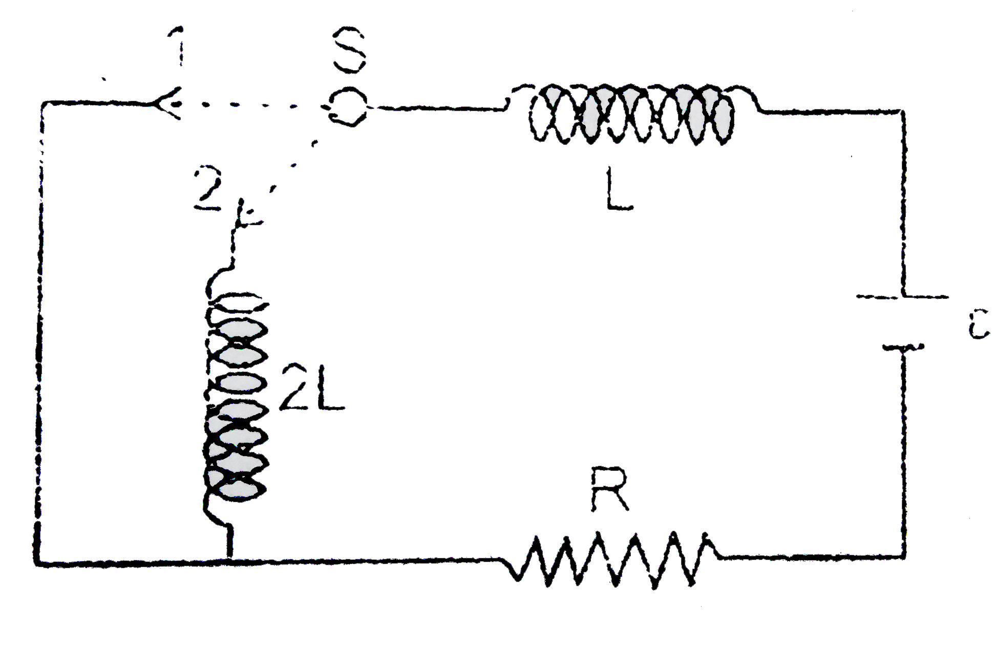
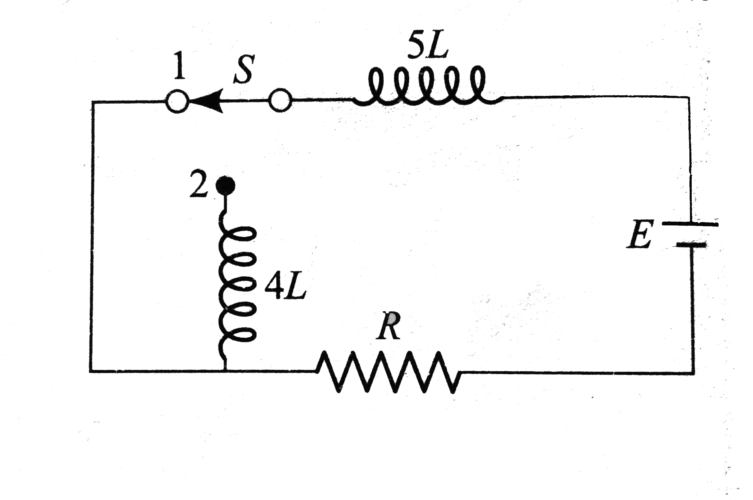
In the circuit shows in Fig switch S is shifed to position 2 from position 1 at t=0, having been on position 1 for a long time. The current in the circuit just after shifting of switch will be (battery and both the inductors are ideal)
45ER
54ER
59ER
ER
The correct Answer is:C
Let i1 be the current in the circuit before shifting
i1=ER (i)
Since the flux associated with the inductors will be same just before and juse after shifting, therefore
i15L=i29L
i2=59ER
Topper's Solved these Questions
- INDUCTANCEBOOK - CENGAGE PHYSICSCHAPTER - INDUCTANCEEXERCISE - Exercises (multiple Correct )
7 Videos
- INDUCTANCEBOOK - CENGAGE PHYSICSCHAPTER - INDUCTANCEEXERCISE - Exercises (assertion-reasoning)
2 Videos
- INDUCTANCEBOOK - CENGAGE PHYSICSCHAPTER - INDUCTANCEEXERCISE - Exercises (subjective)
7 Videos
- HEATING EFFECT OF CURRENTBOOK - CENGAGE PHYSICSCHAPTER - HEATING EFFECT OF CURRENTEXERCISE - Thermal Power in Resistance Connected in Circuit
28 Videos
- KINETIC THEORYBOOK - CENGAGE PHYSICSCHAPTER - KINETIC THEORYEXERCISE - Question Bank
31 Videos
Similar Questions
Knowledge Check
In the circuit shows in Fig the switch is closed at t=0.
 AAt t=0,I1=I2=0BAt any time t,I0I2=L2L1CAt any time t, I1+I2=εRDAt t=∞,I1 and I2 are independent of L1 and L2
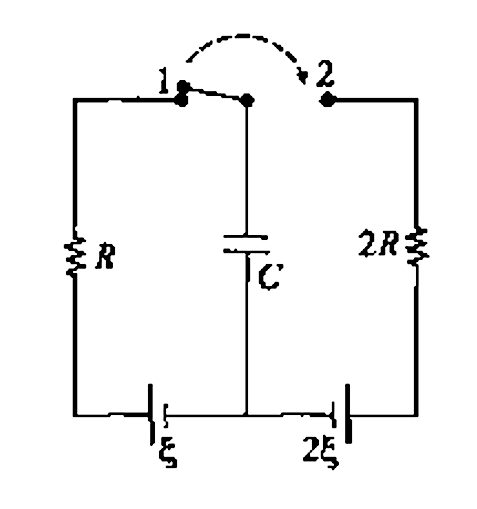
In the given circuit diagram figure, switch Sw is shifted from position 1 to position 2. Then
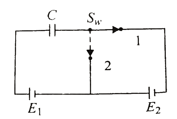 Aa charge of amount CE2 will be supplied to battery E1.Bheat generated in the circuit is CE22/2Ca charge of amount CE2 will be supplied by battery E1.Dheat generated in the circuit is CE1E2/2
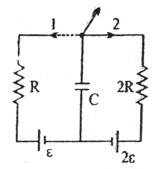
In the circuit shown, the switch is shifted from position 1rightarrow 2 at t=0. The switch was initially in position I since a long time. The graph between charge on capacitor C and time 't' is
 A
A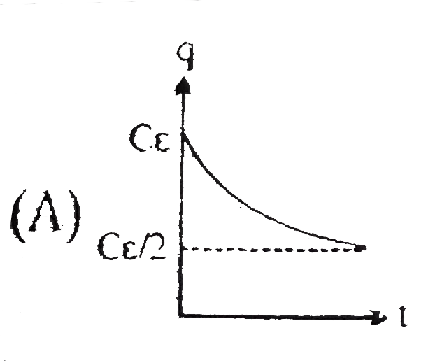 B
B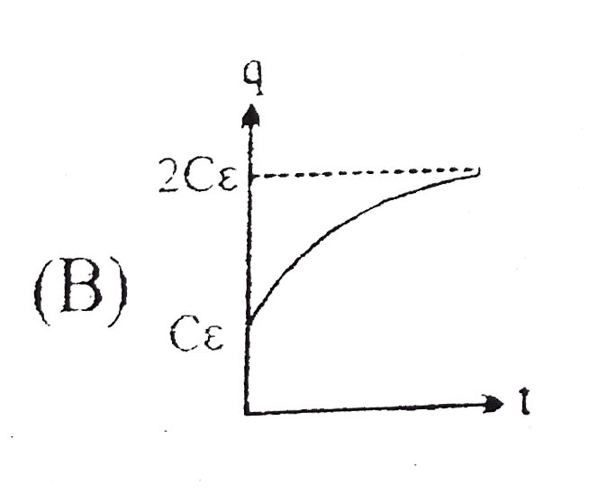 C
C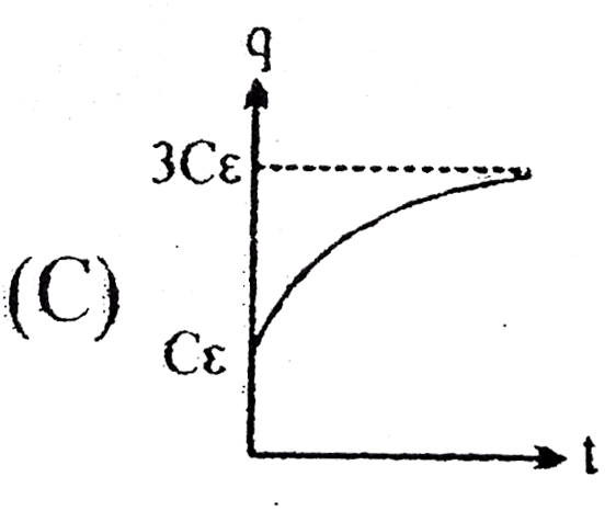 D
D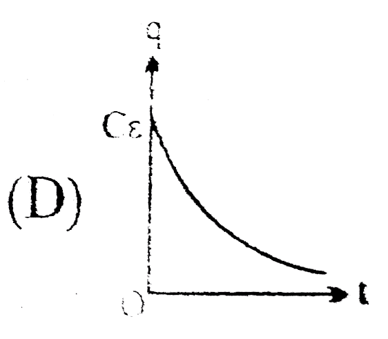
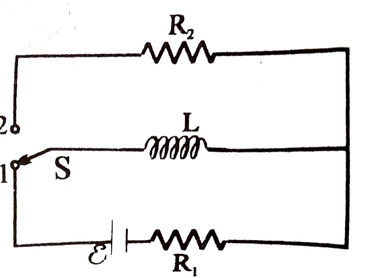
In the circuit shown, initially the switch is in position 1 for a long time. Then the switch is shifted to position 2 for a long time. Find the total heat produced in R2
View SolutionIn the circuit shown in figure switch S is closed at time t=0
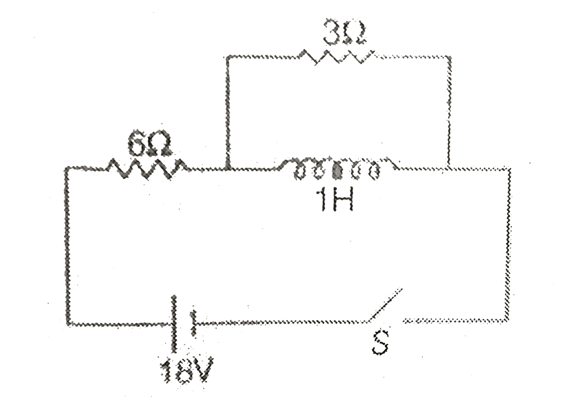
Current I from the battery at time t is given by
View SolutionIn the circuit shown in figure switch S is thrown to position 1 at t=0. when the current in the resistor is 1A, it is shifted to position 2. the total heat generated in the circuit after shifting to position 2 is
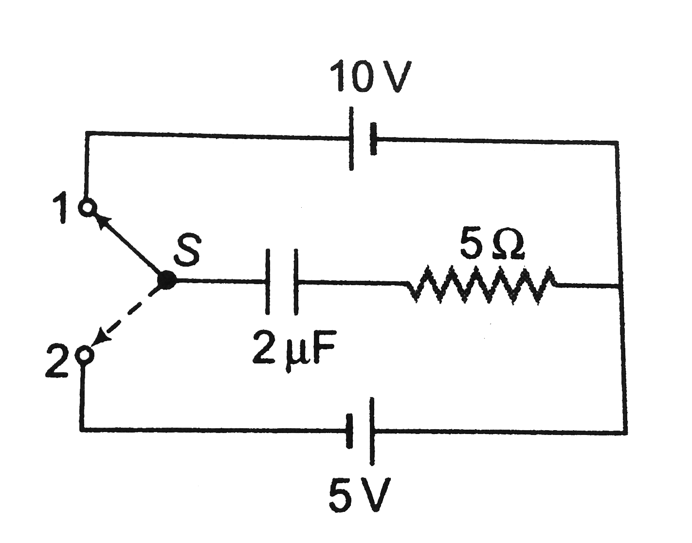
View SolutionIn the circuit shown in figure-3.311, the switch is shifted from position I to 2 at time t = 0. The switch was initially in position I for a long time. The graph between charge on capacitor C and time tis best represented as
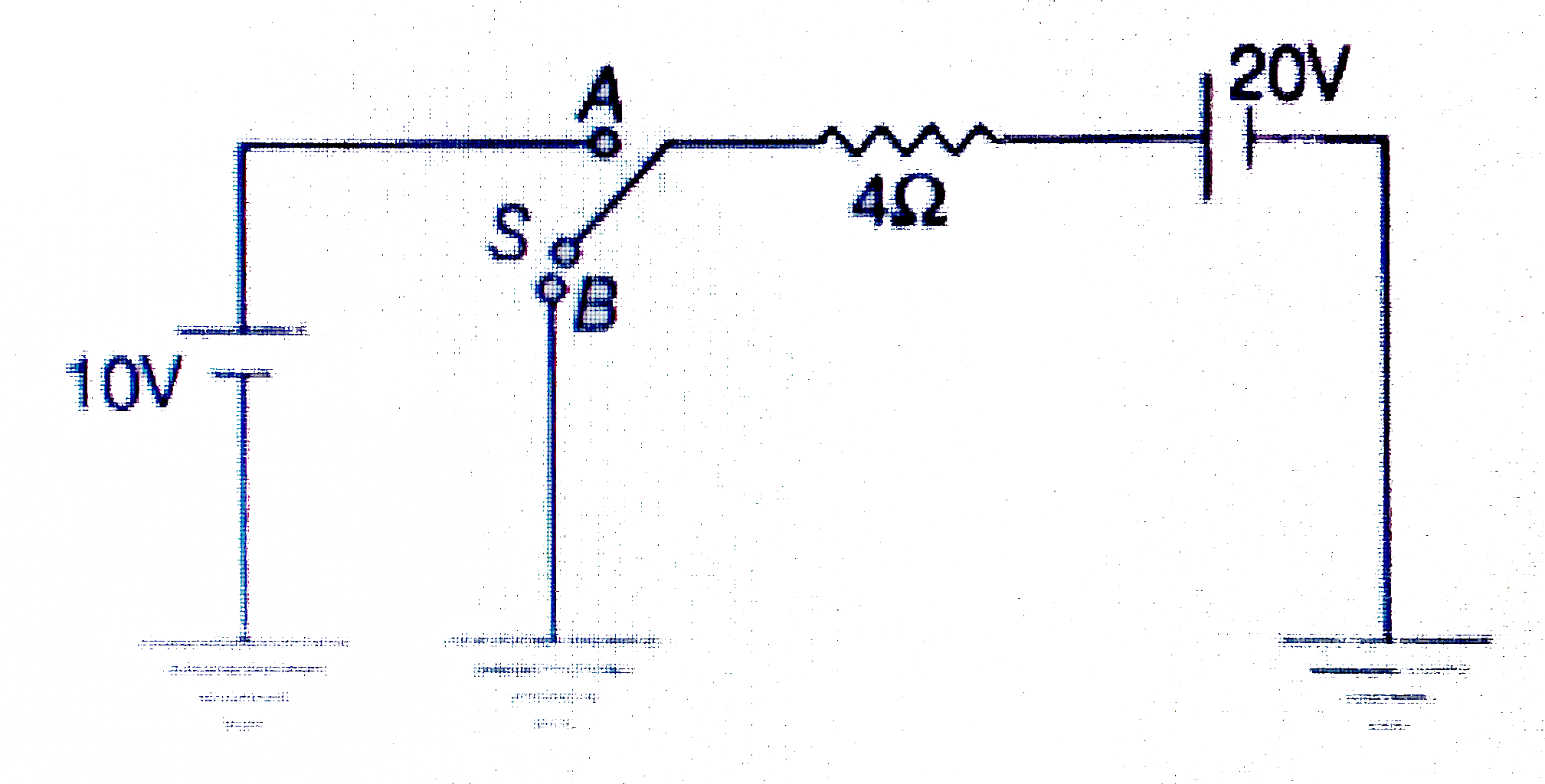
View SolutionIn the circuit shown in figure switch S can be shift to position A or position B. Current though resistance is say i1 when switch is in position. A and when switch is in position B, then
View Solution

