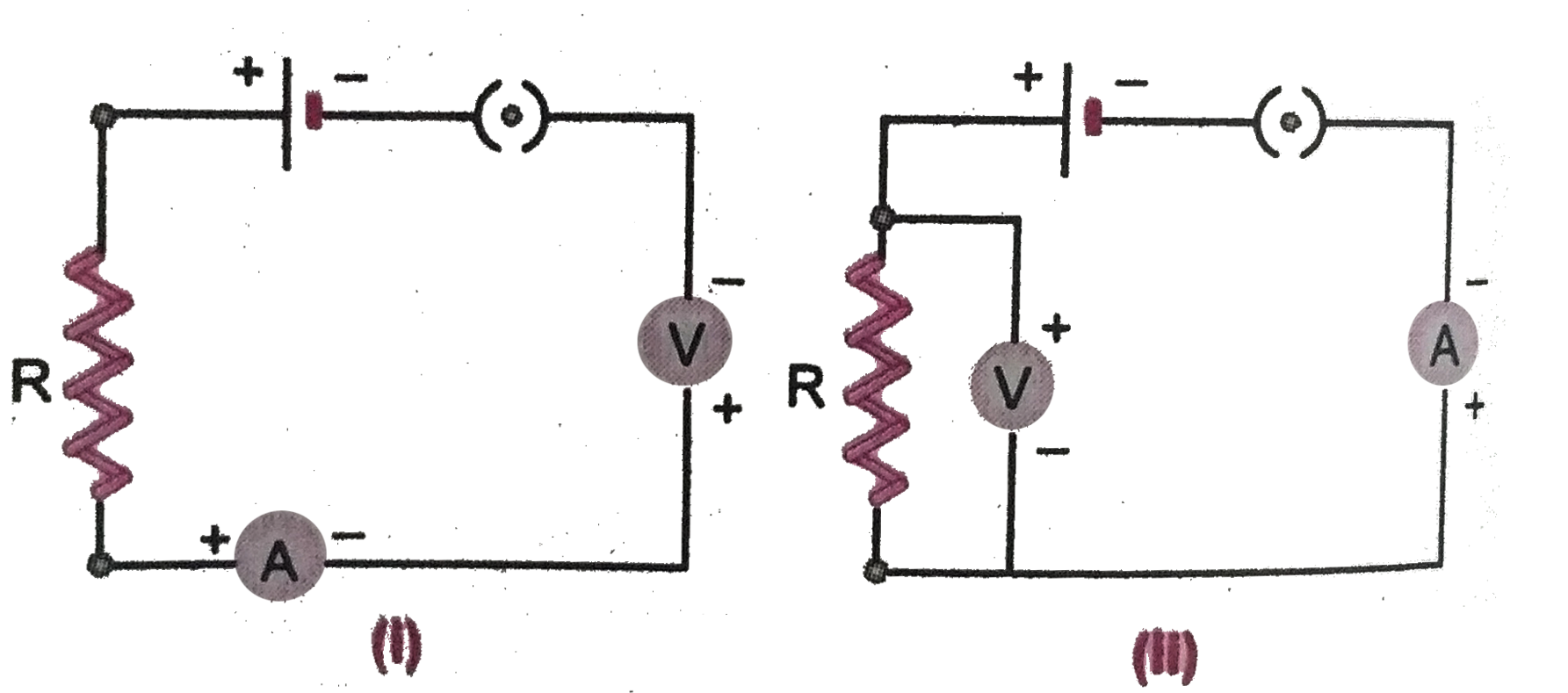
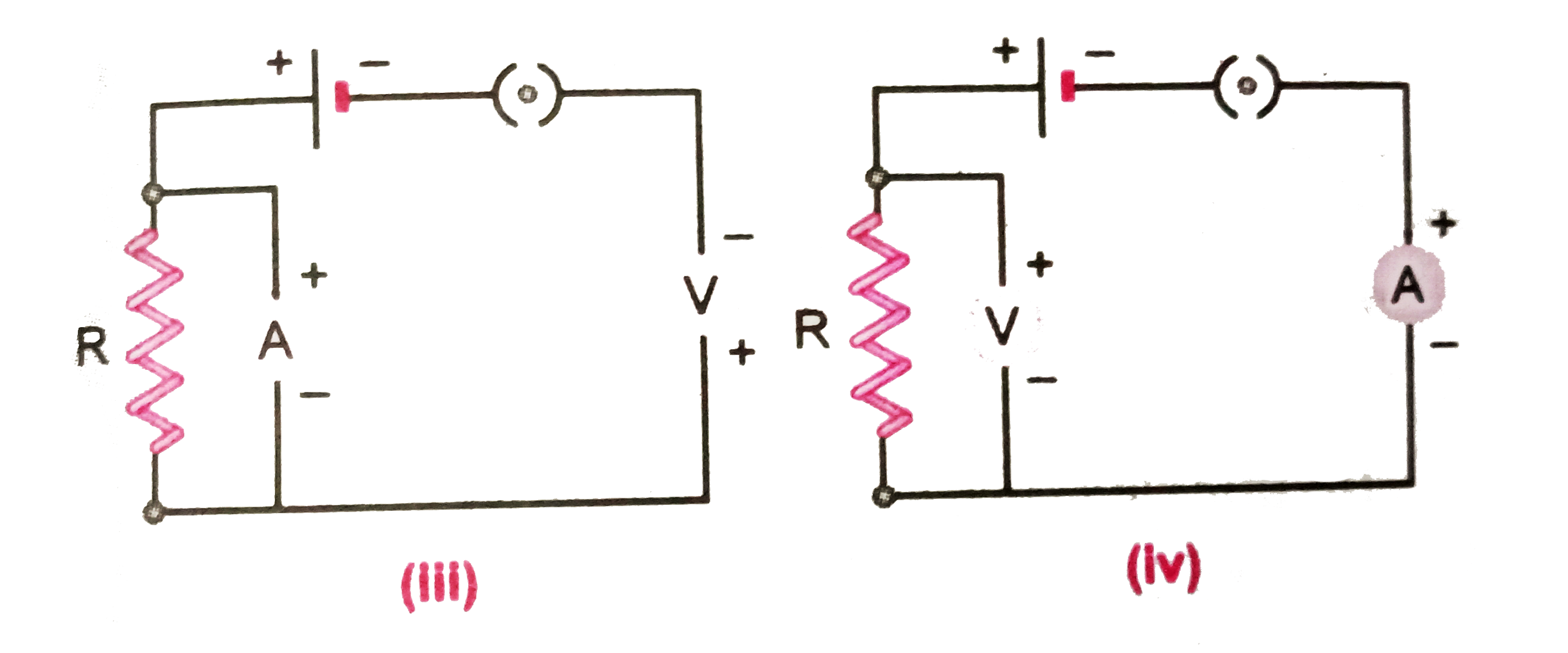
Identify the circuit, (Fig.) in which the electrical components have been properly connected.
(i)
(ii)
(iii)
(iv)
The correct Answer is:B
(i) Positive terminals of VandA should be joined to positive terminal of the cell and their negative terminals should be joined to the negative terminal of the cell. (ii) The voltmeter (V) should be connected in parallel and the ammeter (A) should be connected in series. These conditions are satisfied in (Fig.3) (ii).
Topper's Solved these Questions
- ELECTRICITYBOOK - PRADEEPCHAPTER - ELECTRICITYEXERCISE - (Mock Test)Sec -A
21 Videos
- ELECTRICITYBOOK - PRADEEPCHAPTER - ELECTRICITYEXERCISE - (Mock Test)Sec - B
6 Videos
- ELECTRICITYBOOK - PRADEEPCHAPTER - ELECTRICITYEXERCISE - Problem For Practice
59 Videos
- MAGNETIC EFFECTS OF ELECTRIC CURRENTBOOK - PRADEEPCHAPTER - MAGNETIC EFFECTS OF ELECTRIC CURRENTEXERCISE - Mock Test
21 Videos
Similar Questions
Knowledge Check
Name the electrical components having the following symbols :
 ABatteryBResistorCBulbDCell
Two students made two circuits A and B to determine the resultant resistance of two resistors R1 and R2 connected in series :
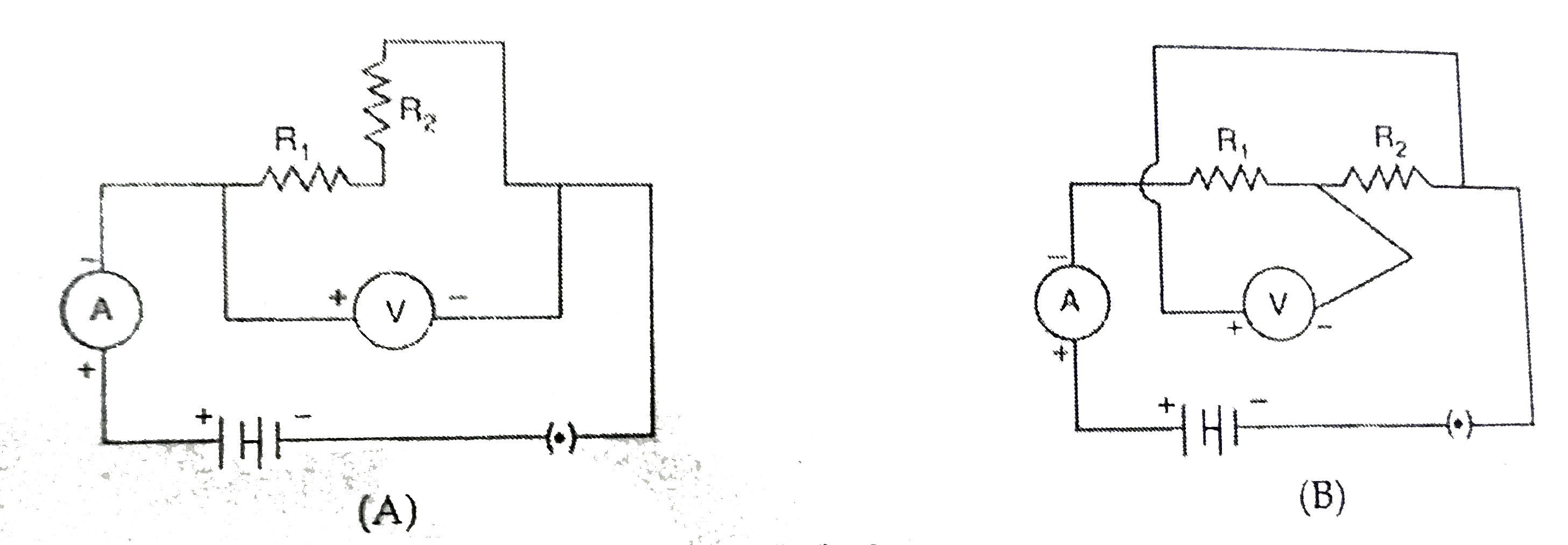
All the components have been connected correctly in :Acircuit A onlyBcircuit B onlyCboth circuits A and BDneither of the two circuitsMegaliths have been identified as
ACaves for hermitsBBurial sitesCTemple sitesDNone of the above
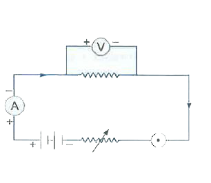
The following circuit diagram shows the experimental set-up for the study of dependence of current on potential difference. Which two circuit components are connected in series?
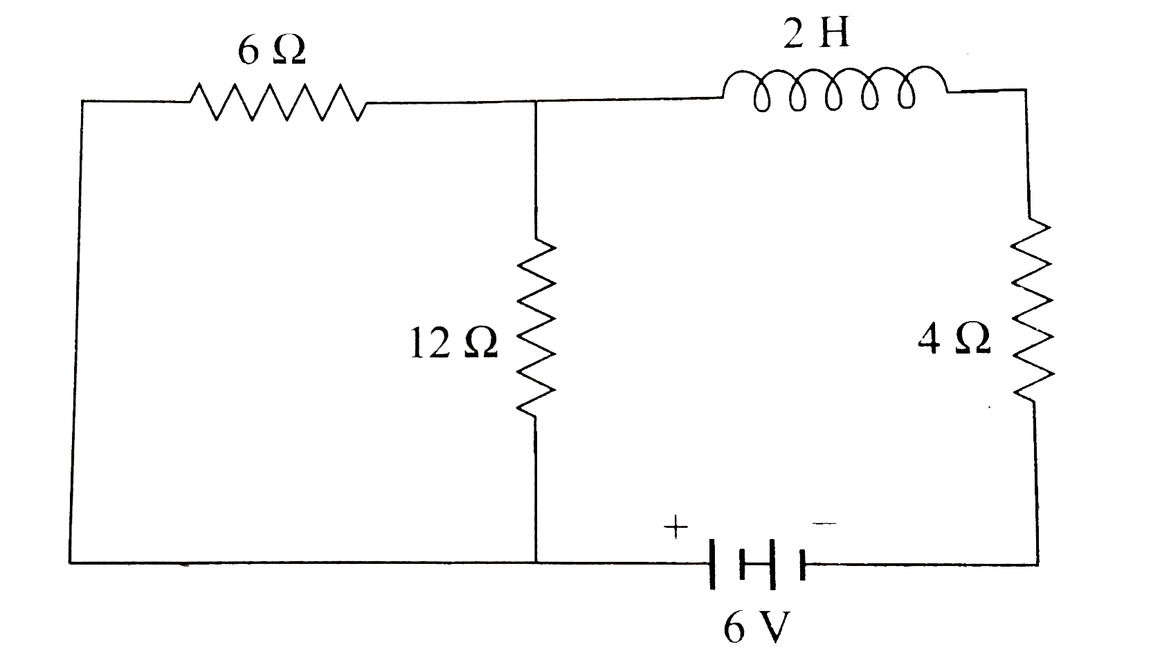
View SolutionFor the circuit shown in Fig. Which of the following statements are correct?
View SolutionFor three circuits, shown here

the same two resistors R1 and R2 have been connected in parallel in all the circuits but the voltmeter and the ammeter have been connected in three different positions. The relation between the three voltmeter and ammeter readings would be :
View SolutionFor the circuit shows in Fig which of the following statements is //are correct?

View SolutionIn the experiment on finding the equivalent resistance of two resistors connected in series, three students connected the ammeter in their circuits in the three ways X, Y and Z shown here.

Assuming their ammeters to be ideal, the ammeters have been correctly connected in
View Solution
