In the shown circuit, all three capacitor are identical and have capacitance CμF each. Each resistor has resistance of RΩ. An ideal cell of emf V volts is connected as shown. Then the magnitude of potential difference across cpacitor C3 in steady state is :

V3
V2
29V
34V
No current passes through capacitors in steady state Assume potential at point '4' to be zero. Then points '1' and '2' are at same potential 2V3 .
Hence C1 and C2 can be take in parallel.
The potential at point 3 is V3 .
∴ Equivalent circuit of all three capacitors is show Hence potential difference across capacitor C3 is
=2C2C+C×(2V3−V3)=2V9

Topper's Solved these Questions
Similar Questions
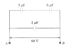
In the circuit shown in the following the potential difference across the 3μF capacitor is
View SolutionA tetrahedral is consisting of 6 identical wires as shown in figure. Each wire is having a resistance of 2Ω. When an ideal cell of emf 2V is connected across AB, as shown then the current through CD is

View Solution
Knowledge Check
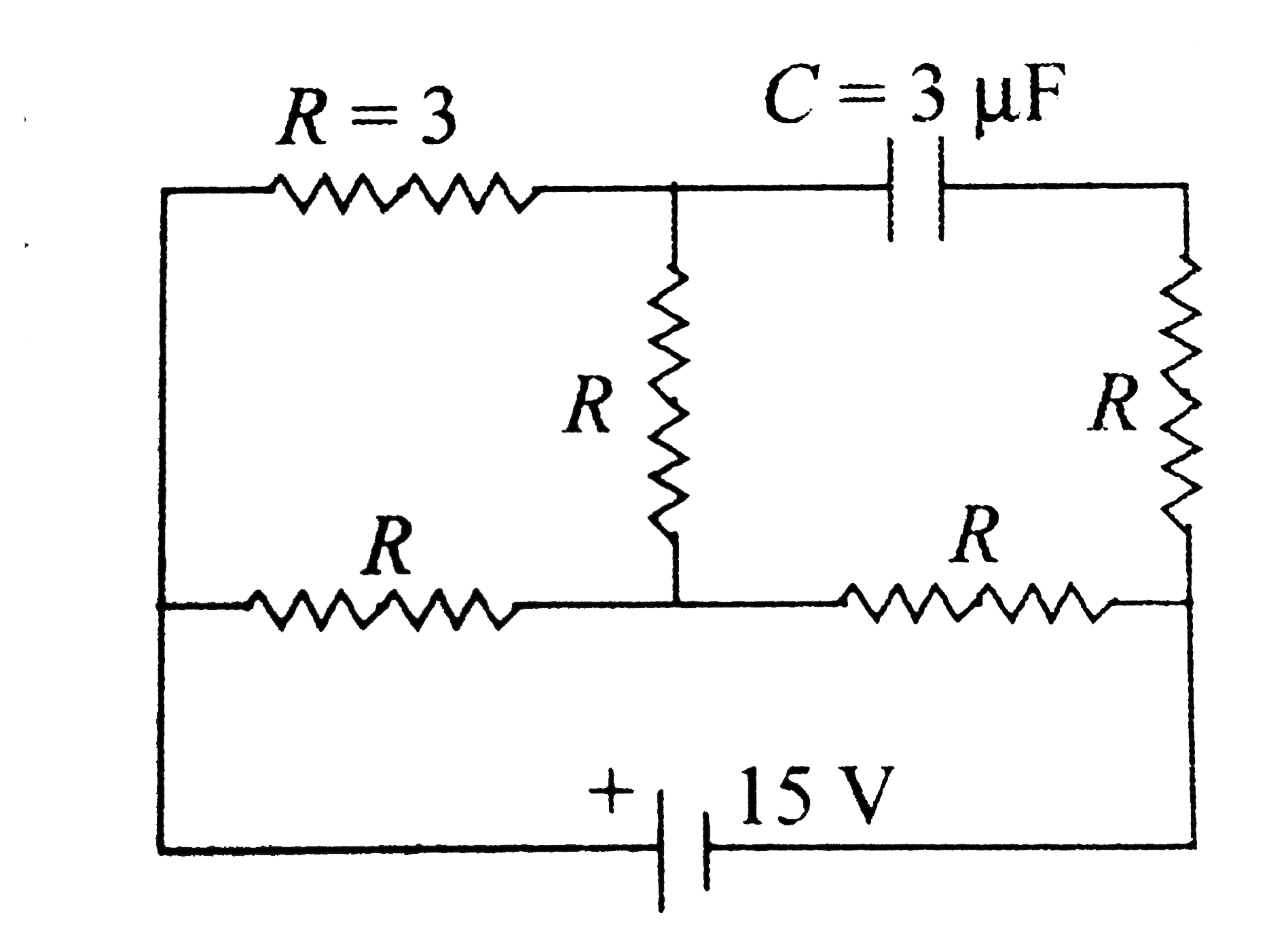
In the circuit shown in fig. the cell is ideal with emf 15V. Each resistance is of 3Ω. The potential difference across the capacitoro in steady state is
 A0B9 VC12 VD15 V
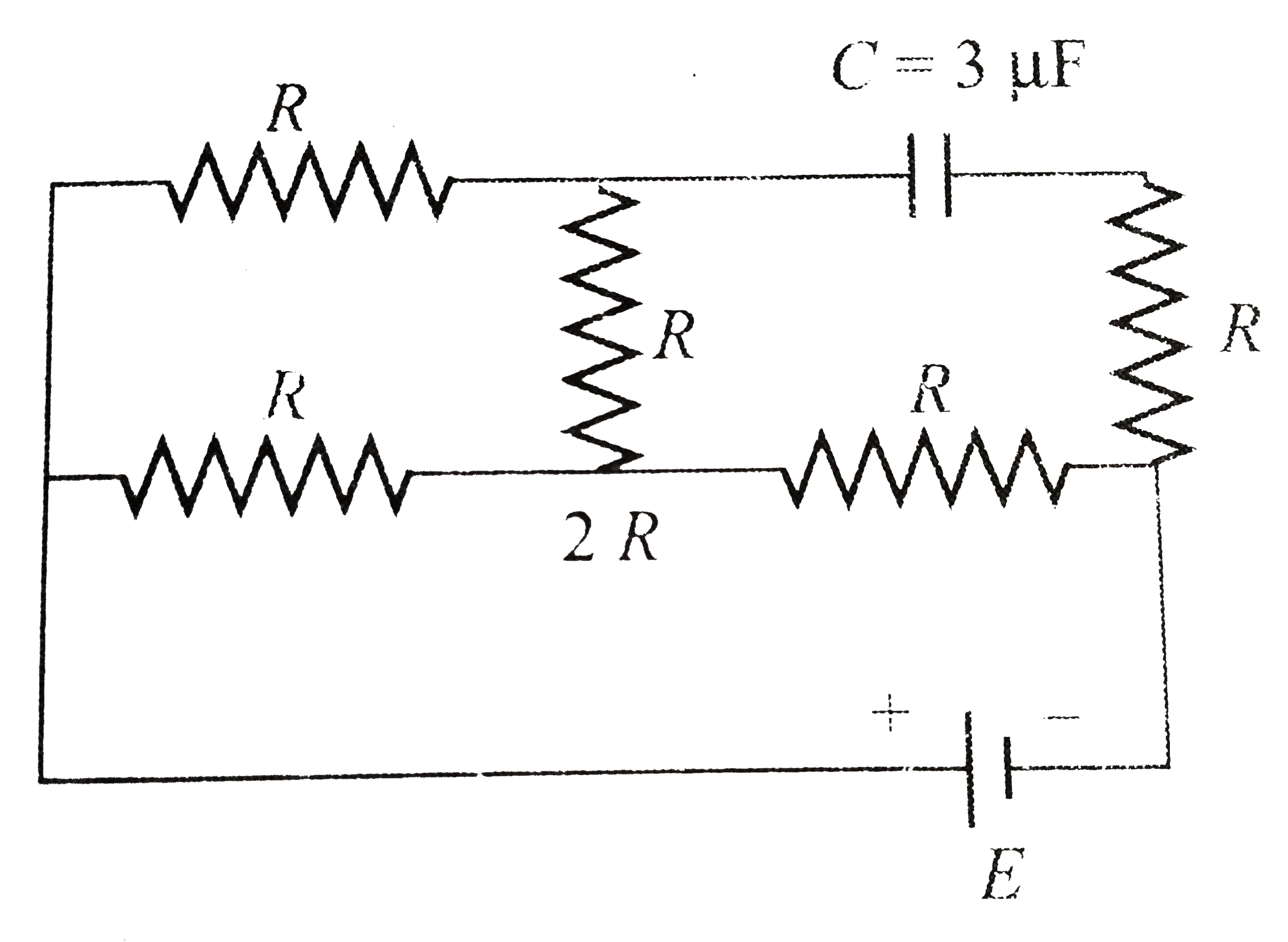
In the given circuit , the potential difference across the capacitor is 12 V. Each resistance is of 3Ω. The cell is ideal. The emf of the cell is
 A15 VB9 VC12 VD24 V
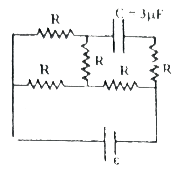
In the given circuit, the potential difference across the capacitor is 12V. Each resistance is of 3Ω. The cell is ideal. The emf of the cell is
 A15VB9VC12VD24V
In the circuit shown in fig. the cell is ideal with emf 15V. Each resistance is of 3Ω. The potential difference across the capacitoro in steady state is

View SolutionSeven identical cells each of e.m.f. E and internal resistance r are connected as shown . The potential difference between A and B is
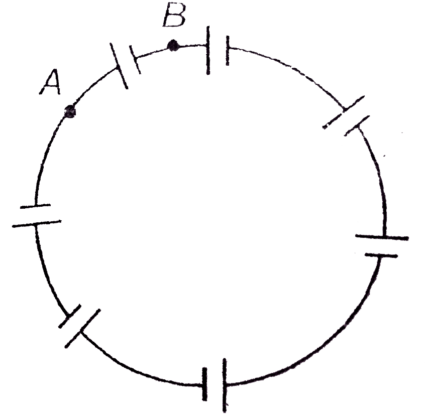
View SolutionSeven identical cells each of e.m.f. E and internal resistance r are connected as shown . The potential difference between A and B is

View SolutionAn ideal cell of emf 10 V is connected in circuit shown in figure. Each resistance is 2Ω . The potential difference (in V) across the capacitor when it is fully charged is _______.
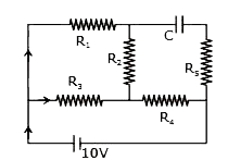
View SolutionAn ideal cell of emf 10 V is connected in circuit shown in figure. Each resistance is 2Ω . The potential difference (in V) across the capacitor when it is fully charged is _______.

View Solution
