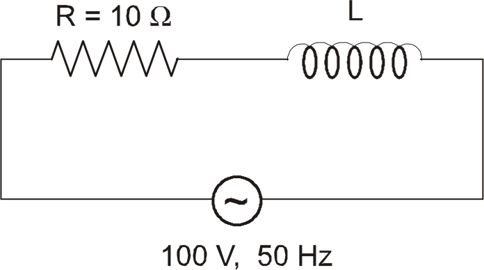
In LR circuit (shown in figure), current is lagging by π3 in phase with applied voltage, then select correct alternative:
L=10√3πH,i=10A
L=10πH,i=5A
L=10√3πH,i=5A
L=√310πH,i=5A
XLR=√3⇒xL=R√3
i=100√(10√3)2+(10)2=5A
L=10√3100π=√310πH
Topper's Solved these Questions
Similar Questions
An alternating voltage of frequency f is applied across a series LCR circuit.Le fr be the resonance frequency for the circuit.Will the current in the circuit lag, lead or remain in phase with the applied voltage when (i)f>fr,(ii)f<fr ? Explain your answer in each case.
View SolutionAn alternating voltage of frequency f is applied across a series LCR circuit.Le fr be the resonance frequency for the circuit.Will the current in the circuit lag, lead or remain in phase with the applied voltage when (i)f>fr,(ii)f<fr ? Explain your answer in each case.
View Solution
Knowledge Check
- Question 1 - Select One
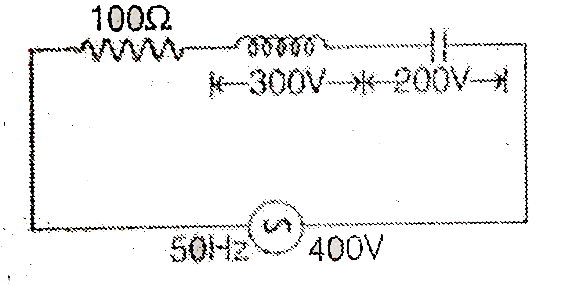
In the circuit shown in figure current in the circuit is
 A1.27AB2.23AC4.26AD4 A
 - Question 2 - Select One
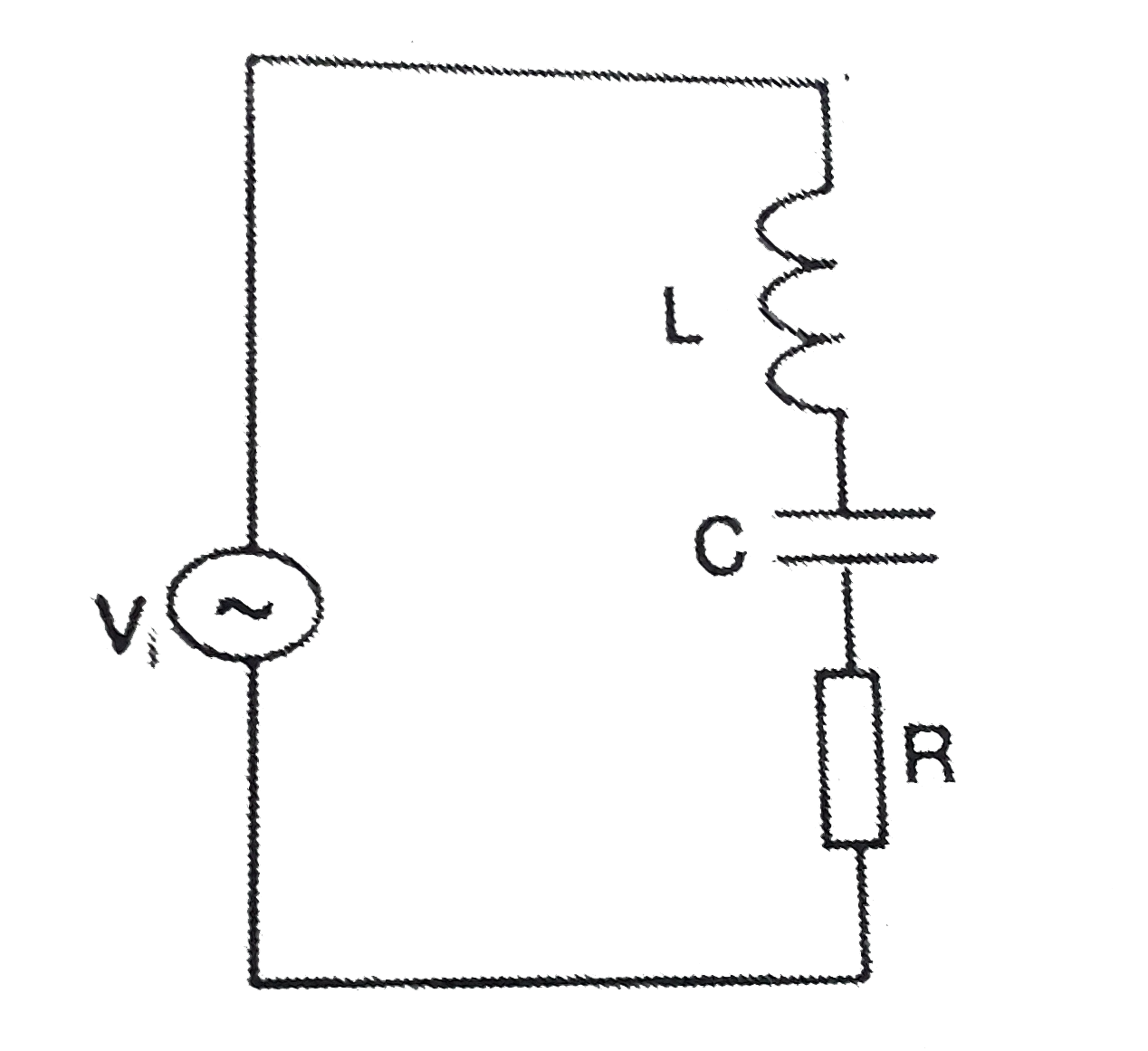
In the following circuit the current is in phase with the applied voltage. Therefore, the current in the circuit and the frequency of the source voltage respectively, are
 AVRand12π√LCBzero and1√LCC√CLv,and2π√LCD√CLR2and2√LC
 - Question 3 - Select One
In the LCR circuit shown in figure
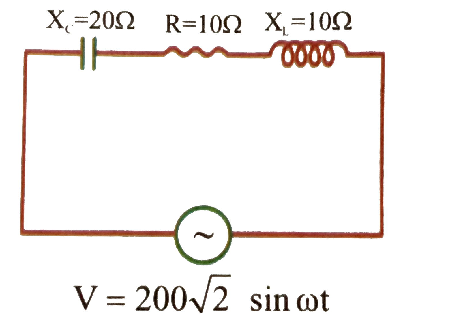
(a) current will lead the voltage
(2) rms value of current in 20A
(3) power factor of the circuit is 1√2
(4) voltage drop across resistance is 100VA(1) and (3) are correctB(1) and (4) are correctC(2) and (3) are correctD(3) and (4) are correct
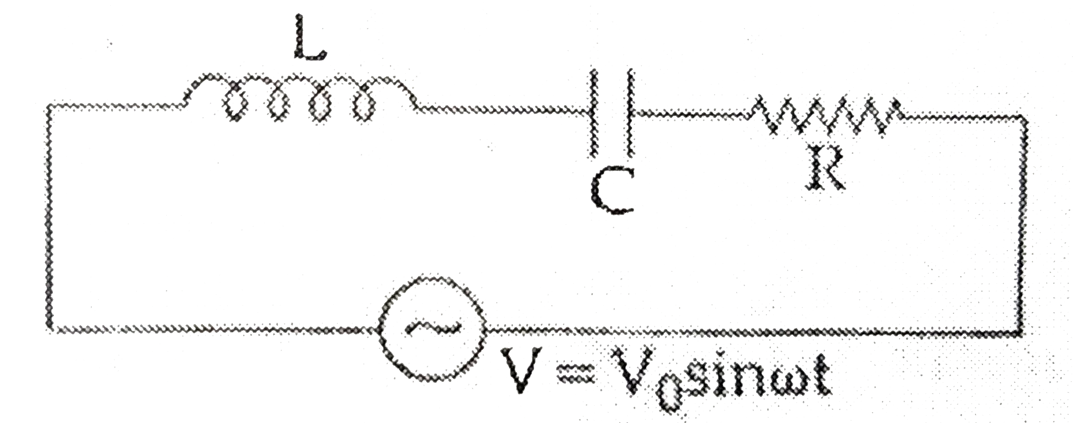
The current in the LCR circuit shown in the figure is observed to lead the voltage in phase. Without making any other change in the circuit, a capacitor, of capacitance C0 is (appropriately) joined to the capacitor C. This results in making the current, in the joined to the capacitor C. This results in making the current, in the modified' circuit, flow in phase with the applied voltage.
Draw a diagram of the modified circuit and obtain an expression of C0 in terms of Ω, L and C.View SolutionWhen an alternating voltage of 220V is applied across a device P, a current of 0.25A flows through the circuit and it leads the applied voltage by a angle π2 radian. When the same voltage source is connected across another device Q, the same current is observed in the circuit but in phase with the applied voltage. What is the current when the same source is connected across a series combination of P and Q?
View SolutionAn LCR circuit is connected to a source of alternating current. At resonance, the applied voltage and the current flowing through the circuit will have a phase difference of
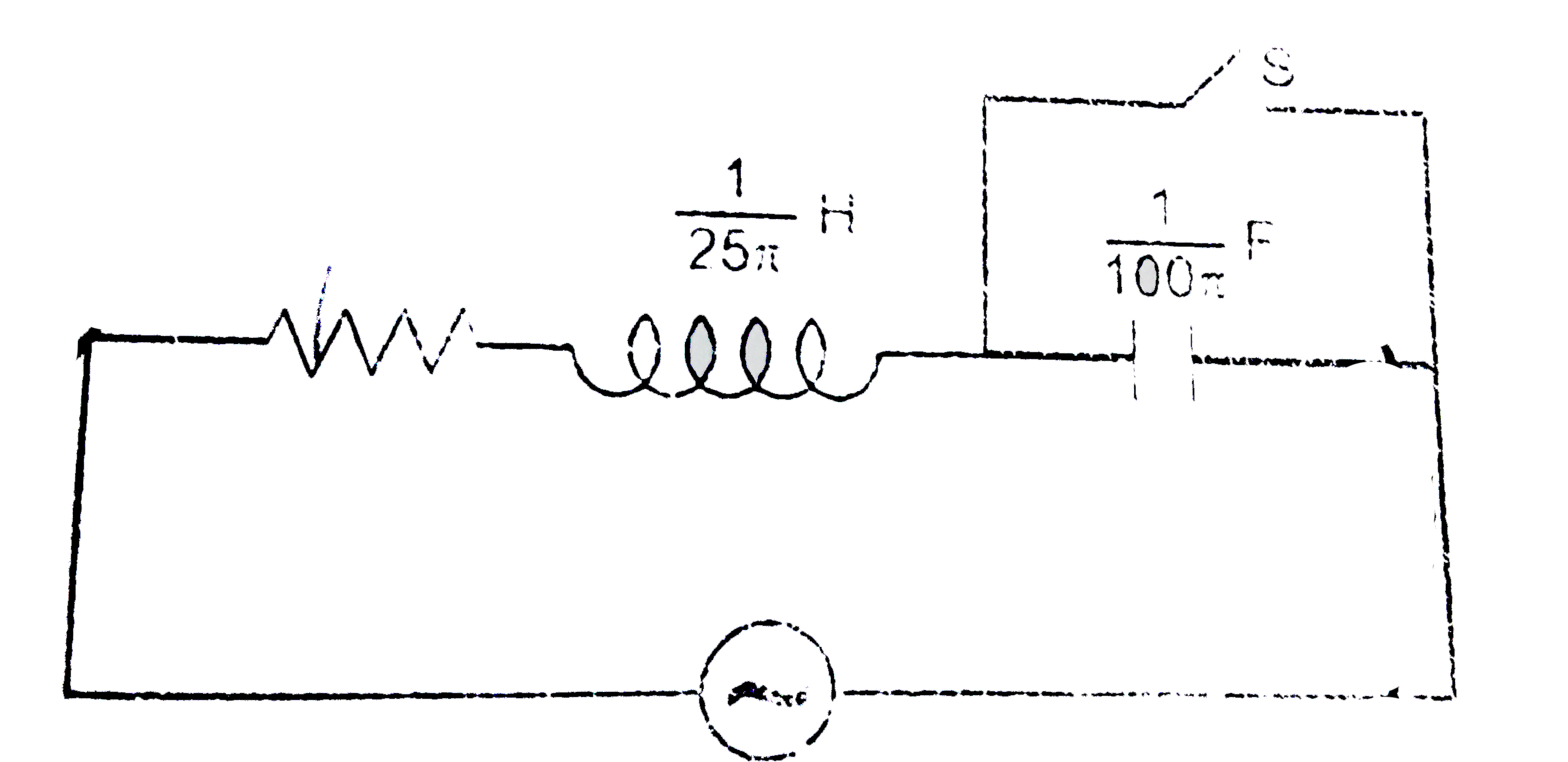
View SolutionIn the LCR circuit shown in figure unknown resistance and alternating voltage source are connected.When swith S is closed then there is a phase difference of π4 between current and applied voltage and voltage across resister is 100√2V.When switch is open current and applied voltage are in same phase.Neglecting resistance of connecting wire answer the following questions :
Peak voltage of applied voltage sources is:
 View Solution
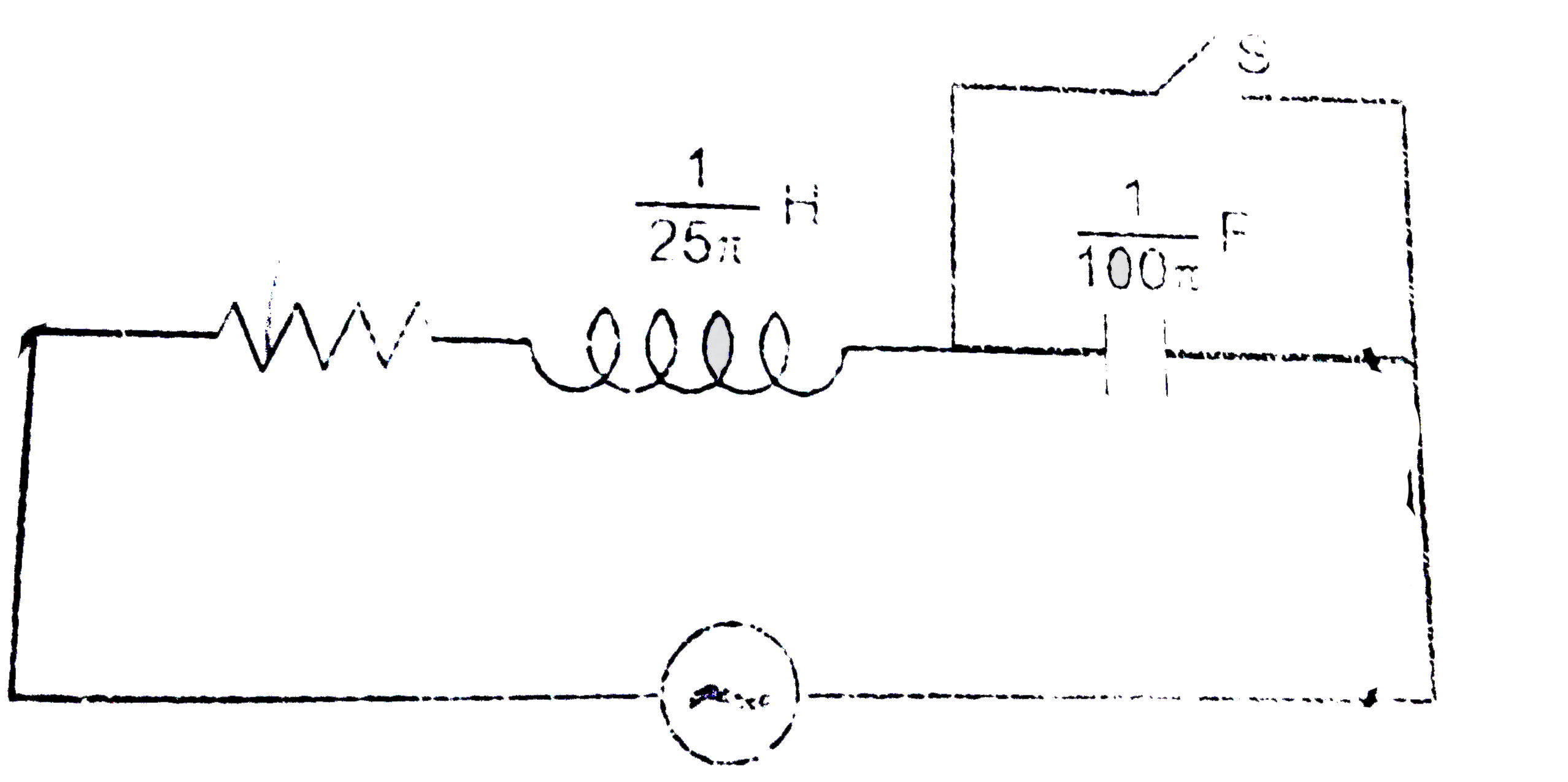
In the LCR circuit shown in figure unknown resistance and alternating voltage source are connected.When swith S is closed then there is a phase difference of π4 between current and applied voltage and voltage across resister is 100√2V.When switch is open current and applied voltage are in same phase.Neglecting resistance of connecting wire answer the following questions :
Resonance frequency of circuit is:
 View Solution

