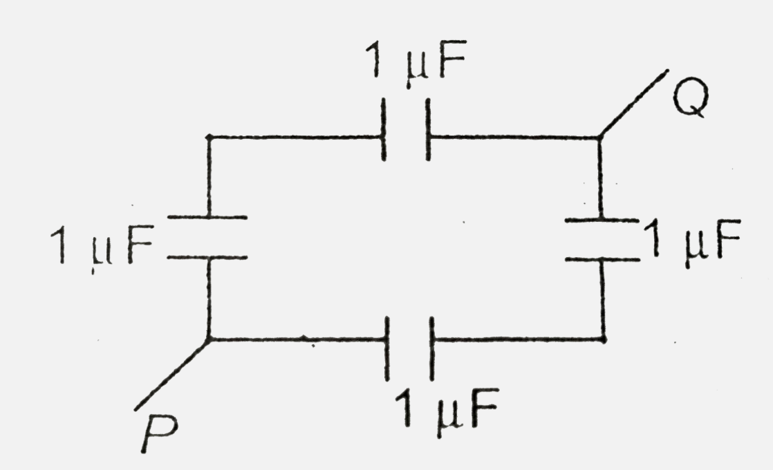
In the circuit diagram shown in the adjoining figure, the resultant capacitance between P and Q is
A
47μF
B
3μF
C
60μF
D
10μF
Video Solution
Text Solution
The correct Answer is:B
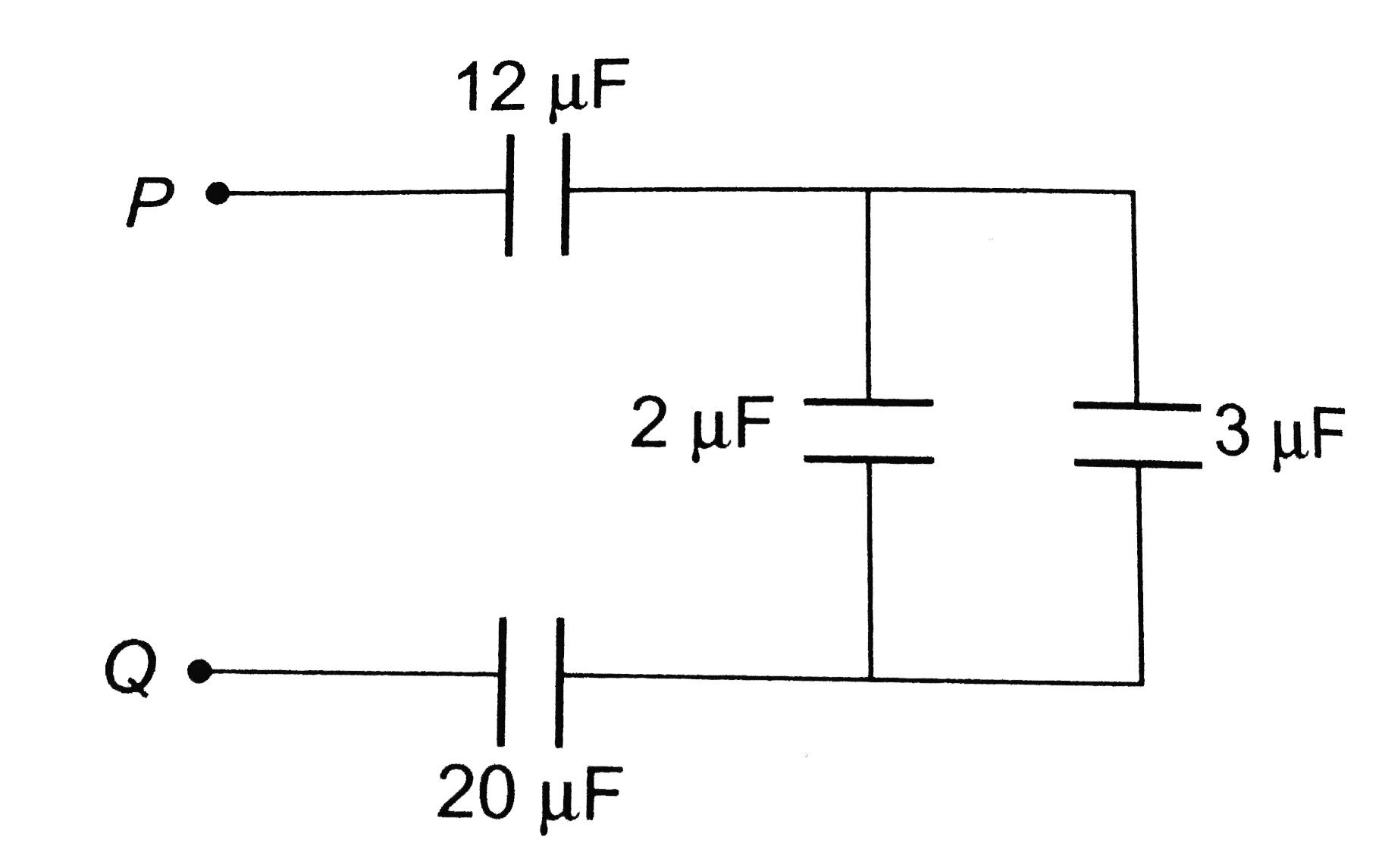
The given circuit can be draws as
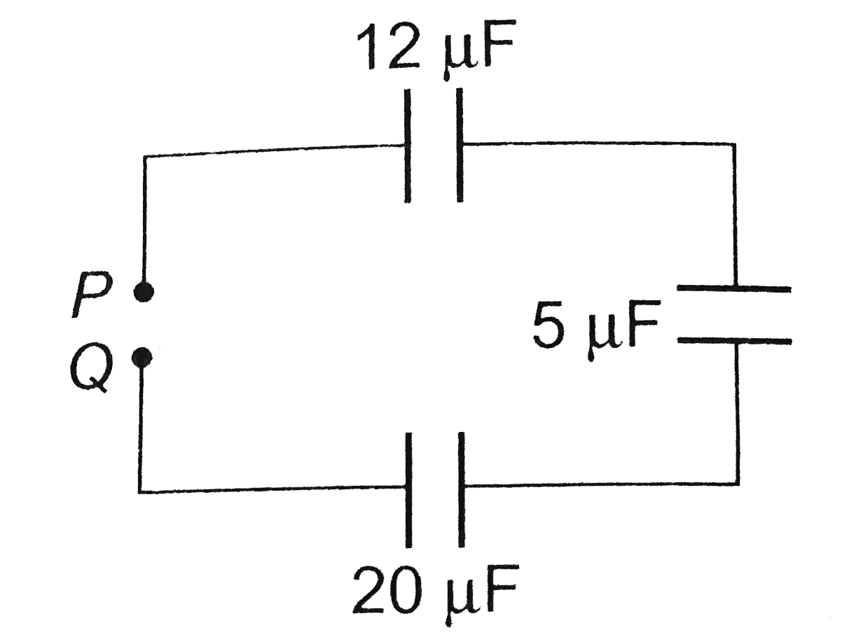
where C=(3+2)μF=5μF
1CPQ=15+120+112=2060=13
⇒CpQ=3μF
|
Updated on:21/07/2023
Topper's Solved these Questions
- BOOK - A2ZCHAPTER - ELECTRIC POTENTIAL & CAPACITANCEEXERCISE - Problems Based On Mixed Concepts44videos
ELECTRIC POTENTIAL & CAPACITANCE
- BOOK - A2ZCHAPTER - ELECTRIC POTENTIAL & CAPACITANCEEXERCISE - Section B - Assertion Reasoning17videos
ELECTRIC POTENTIAL & CAPACITANCE
- BOOK - A2ZCHAPTER - ELECTRIC POTENTIAL & CAPACITANCEEXERCISE - Grouping Of Capacitors48videos
ELECTRIC POTENTIAL & CAPACITANCE
- BOOK - A2ZCHAPTER - ELECTRIC CHARGE, FIELD & FLUXEXERCISE - Section D - Chapter End Test29videos
ELECTRIC CHARGE, FIELD & FLUX
- BOOK - A2ZCHAPTER - ELECTROMAGNETIC INDUCTIONEXERCISE - Section D - Chapter End Test30videos
ELECTROMAGNETIC INDUCTION
Similar Questions
Knowledge Check
- Question 1 - Select One
The equivalent capacitance between P and Q is.
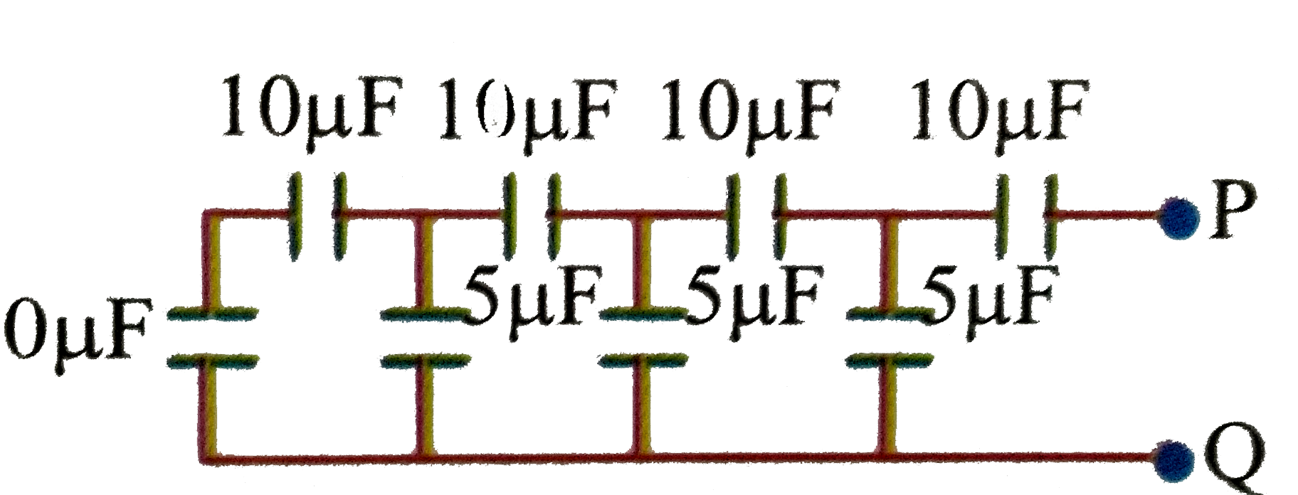 .A10μFB20μFC5μFD15μF
 - Question 2 - Select One
In the connection shown in the adjoining figure, the equivalent capacity between A and B will be
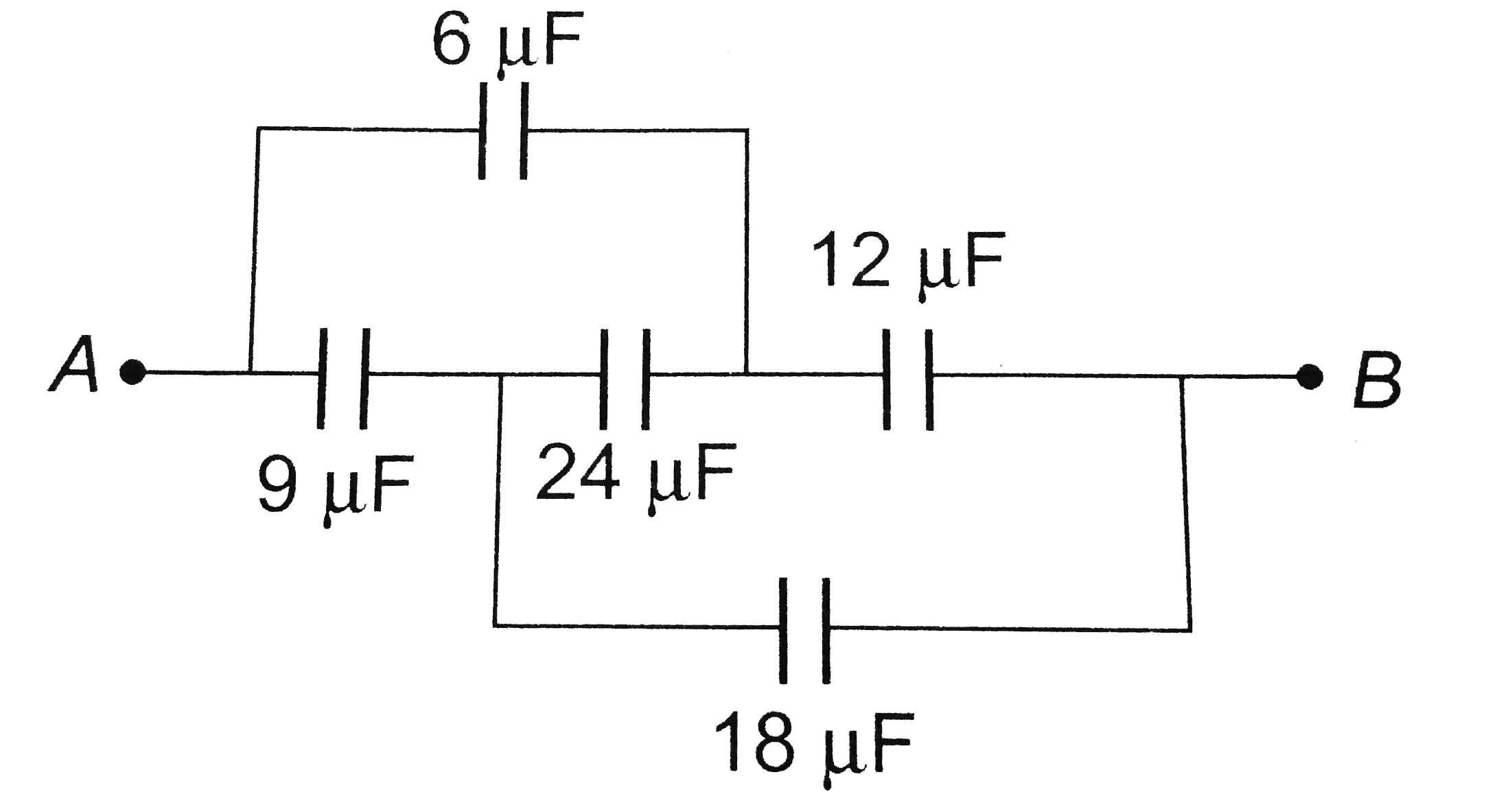 A10.8μFB69μFC15μFD10μF
 - Question 3 - Select One
Five equal capacitors, each with capacitance (C) are connected as shown in the adjoining fig. Then the equivalent capacitance between A and B is -
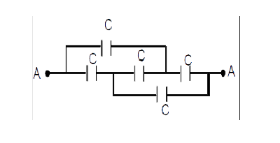 ACB5CCC/5D3C
In the network of resistors shown in the adjoining figure, the equivalent resistance between A and B is
 View Solution
For the circuit, the equivalent capacitance between P and Q is
 View Solution
Four capacitors of each of capacity 3μF are connected as shown in the adjoining figure. The ratio of equivalent capacitance between A and B and between A and C will be
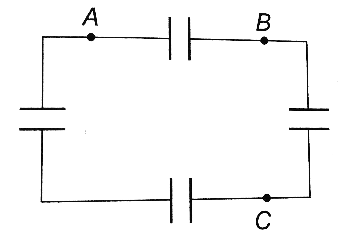 View Solution
In the circuit as shown in the figure the effective capacitance between A and B is
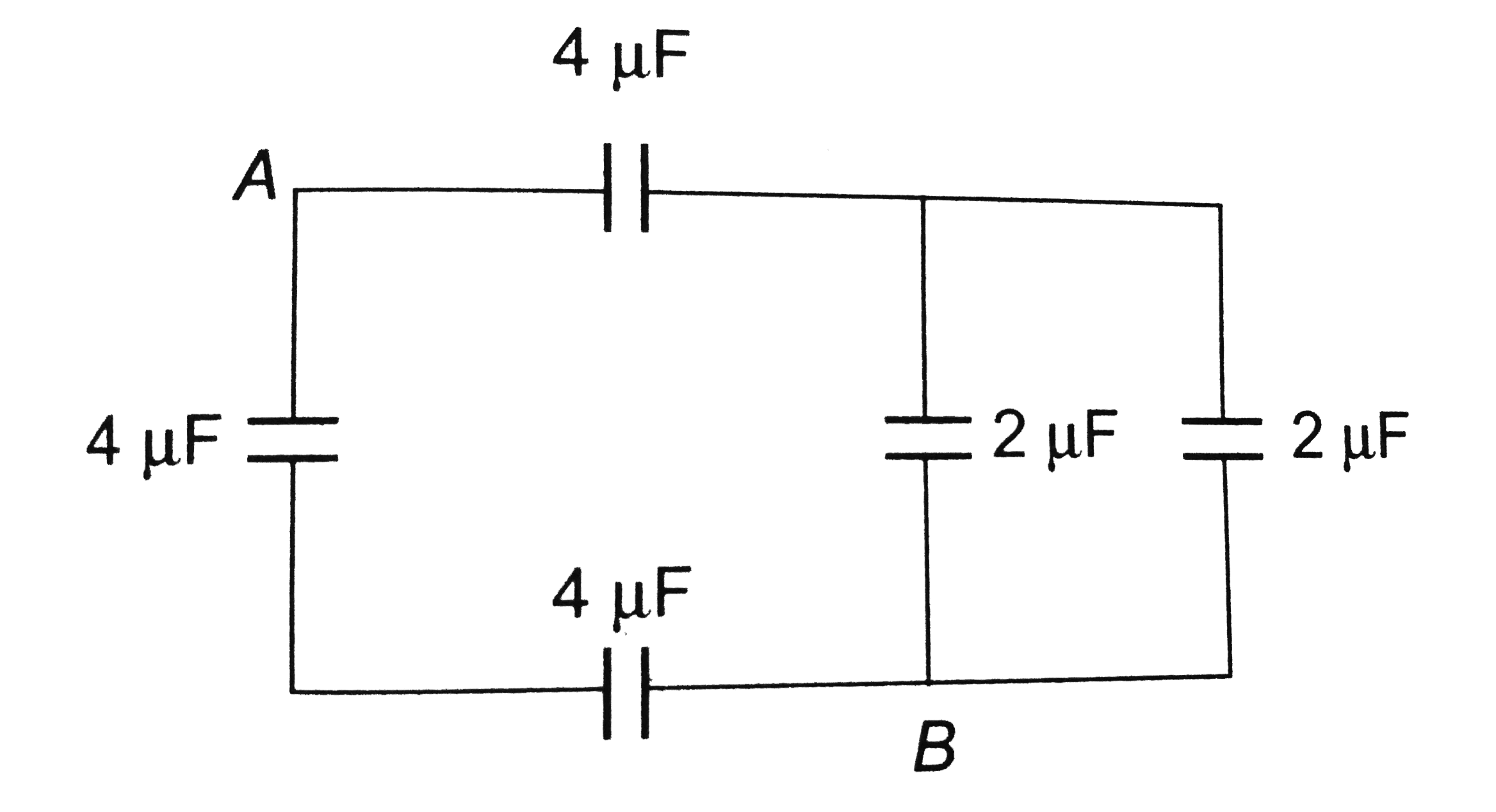 View Solution
In the circuit as shown in the figure the effective capacitance between A and B is
 View Solution


