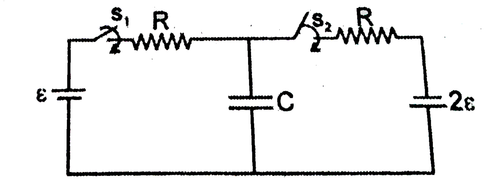
In the circuit shown, S2 is closed first and is kept closed for a long time. Now S1 is closed. Just after that instant the current through S1is
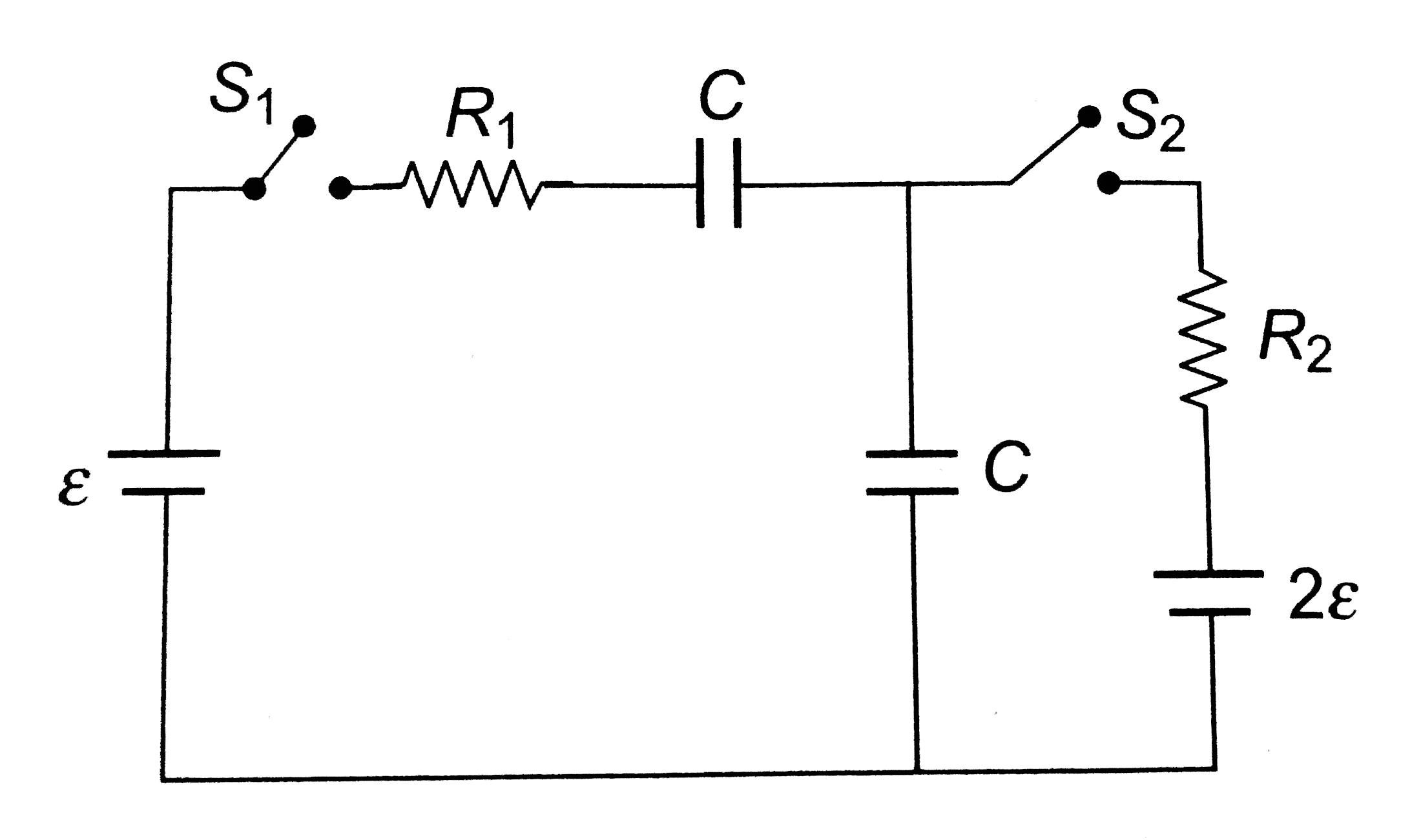
εR1 toward right
εR1 toward left
zero
2εR1
The correct Answer is:B
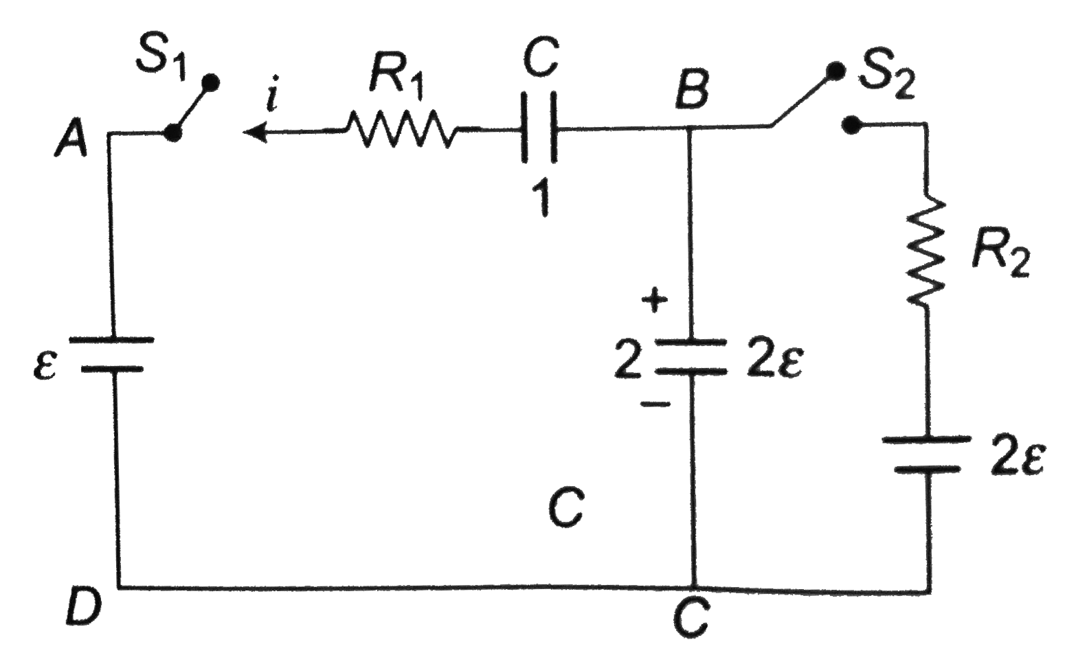
(b) Just before S1 is closed the potential difference across capacitor 2 is 2.
Just after S1 closed the potential difference across capacitor 1 and 2 are 0 and 2, respectively.
If we take potential of C and D to be zero than
VA=ε,VB=2ε
Since VB>VA, so current will flow
i=2ε−εR1=εR1 toward left
Topper's Solved these Questions
- CURRENT ELECTRICITYBook:A2ZChapter:CURRENT ELECTRICITYExercise:Ammeter And Voltmeter
Explore 41 Videos
- CURRENT ELECTRICITYBook:A2ZChapter:CURRENT ELECTRICITYExercise:Potentiometer And Meter Bridge
Explore 45 Videos
- CURRENT ELECTRICITYBook:A2ZChapter:CURRENT ELECTRICITYExercise:Kircoff'S Laws And Simple Circuits
Explore 64 Videos
- ATOMIC PHYSICSBook:A2ZChapter:ATOMIC PHYSICSExercise:Section D - Chapter End Test
Explore 30 Videos
- DUAL NATURE OF RADIATION AND MATTERBook:A2ZChapter:DUAL NATURE OF RADIATION AND MATTERExercise:Section D - Chapter End Test
Explore 30 Videos
Similar Questions
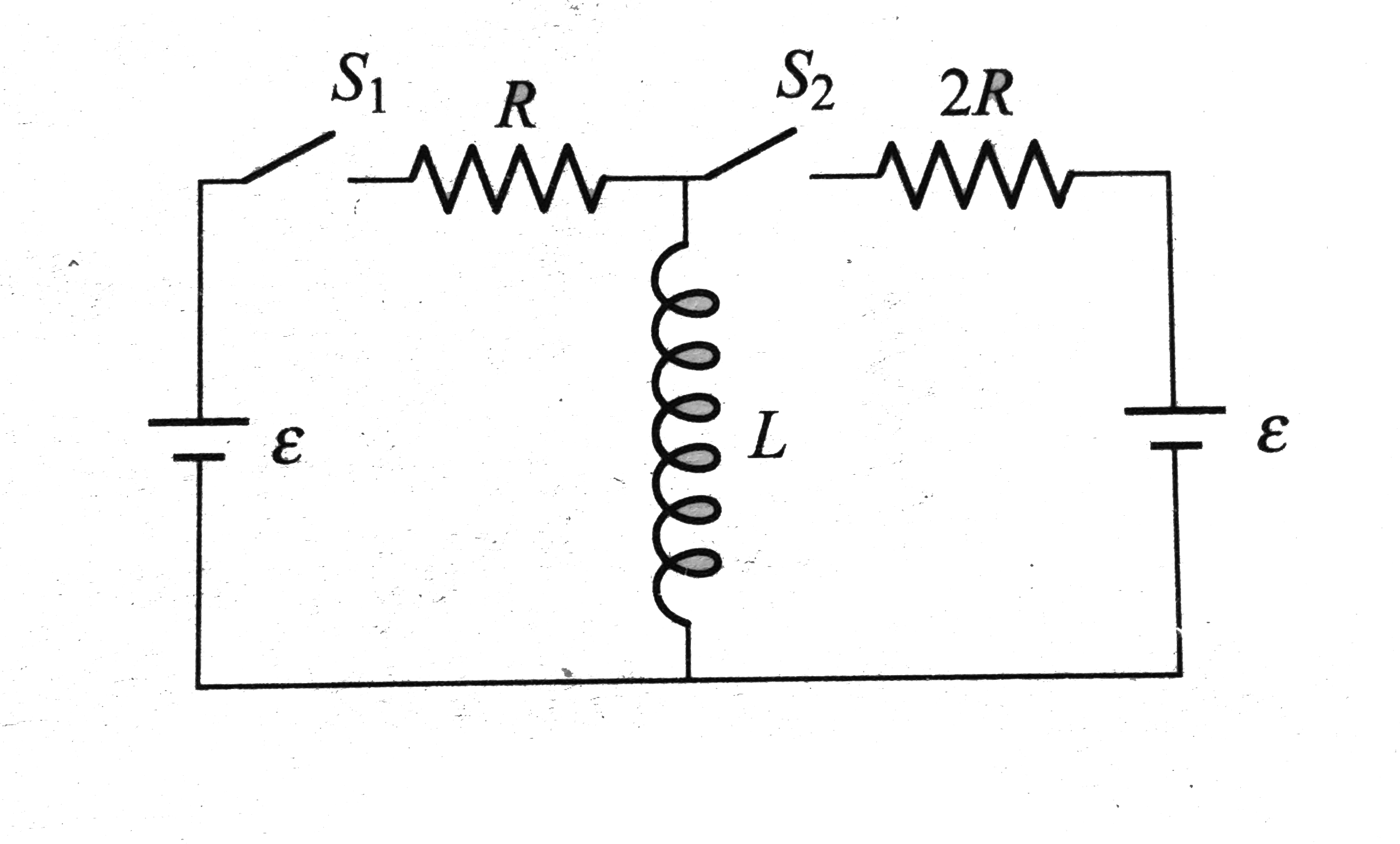
In the circuits shows in S1 and S2 are switches. S2 remains closed for a long time and S1 is opened. Now S1 is also closed. Just after S1 is closed, find the potential difference (V) across R and di/dt (with sign) in L.
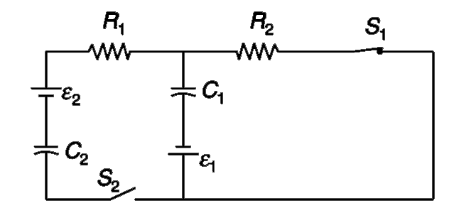
View SolutionIn the circuit shown in the figure R1=R2=5Ω,C1=C2=2μfandε1=ε2=5V. Switch S1 is kept closed for a long time. Now switch S2 is also closed. Immediately after S1 is closed, find
(a) current through R1
(b) current through R2
View Solution
Knowledge Check
In the circuits (A) and (b) switches S1 and S2 are closed at t = 0 and are kept closed for a long time.The variation of current in the two circuits for t≥0 are roughly shown by figure (figures are schematic and not drawn to scale):
 A
A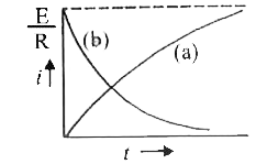 B
B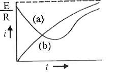 C
C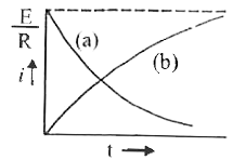 D
D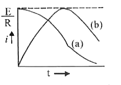
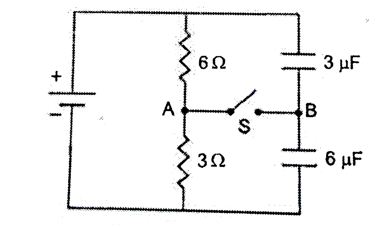
In the circuit shown above, when then switch S is closed,Ano charge flows through SBcharge flows from A to BCcharge flows from B to ADcharge flows initially from A to B and later from B to AIn the circuit shown in the figure, if switches S1 and S2 have been closed for a long time, then charge on the capacitor.
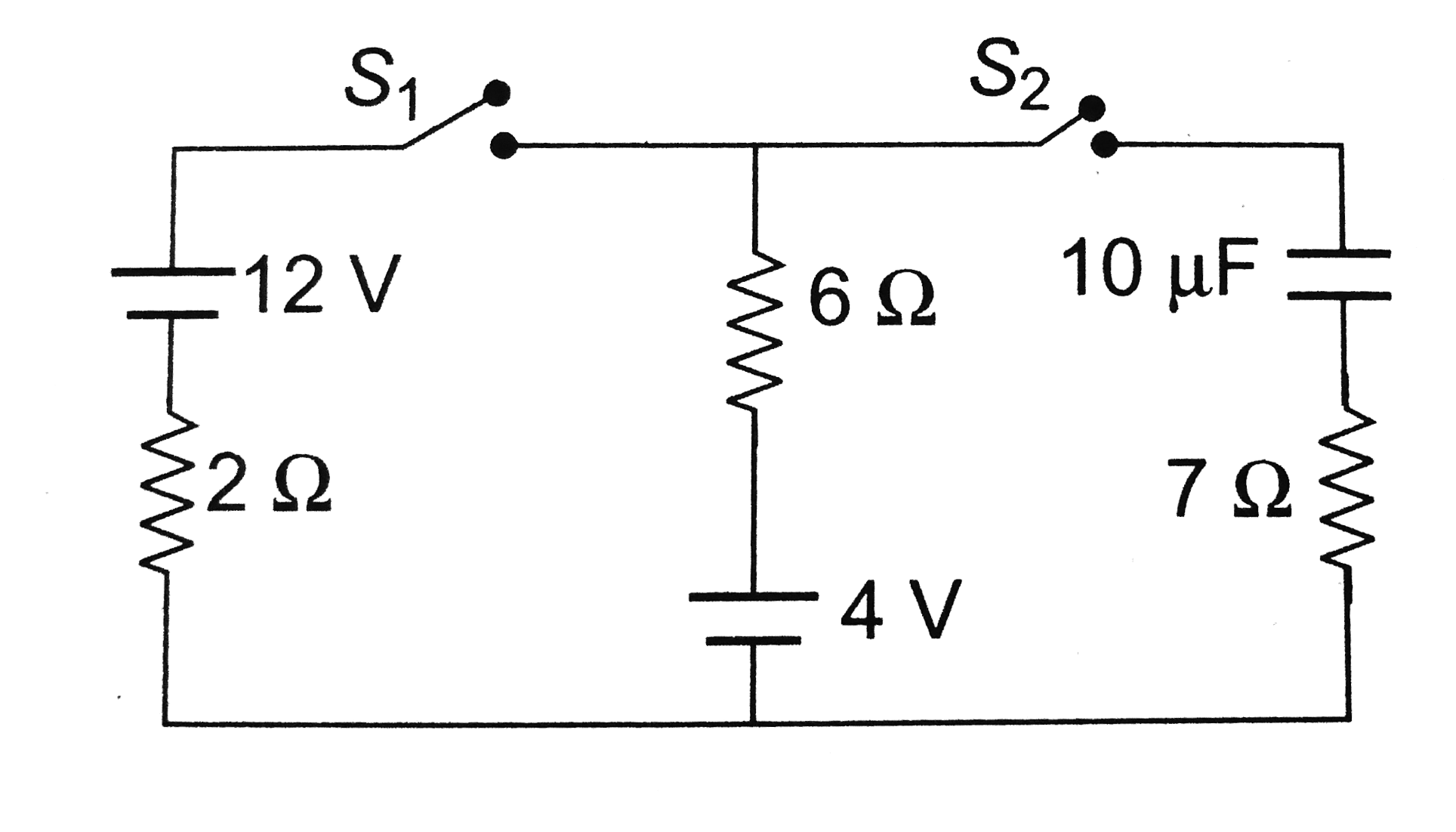 Ais 100μCBincreases to 200μC if one third of the gap of the capacitor's plates is filled with a dielectric (K=2) of same areaCboth (a) and (b) aboveDcharge on the capacitor remains unchanged if one third of the gap of the capacitor's plates is filled with a dielectric (K=2) of same area.
In the given circuit switch S2 is Kept closed and S1 is kept open for a very long time such that the system is in steady- state . Now S1 is also slosed keeping S2 closed.
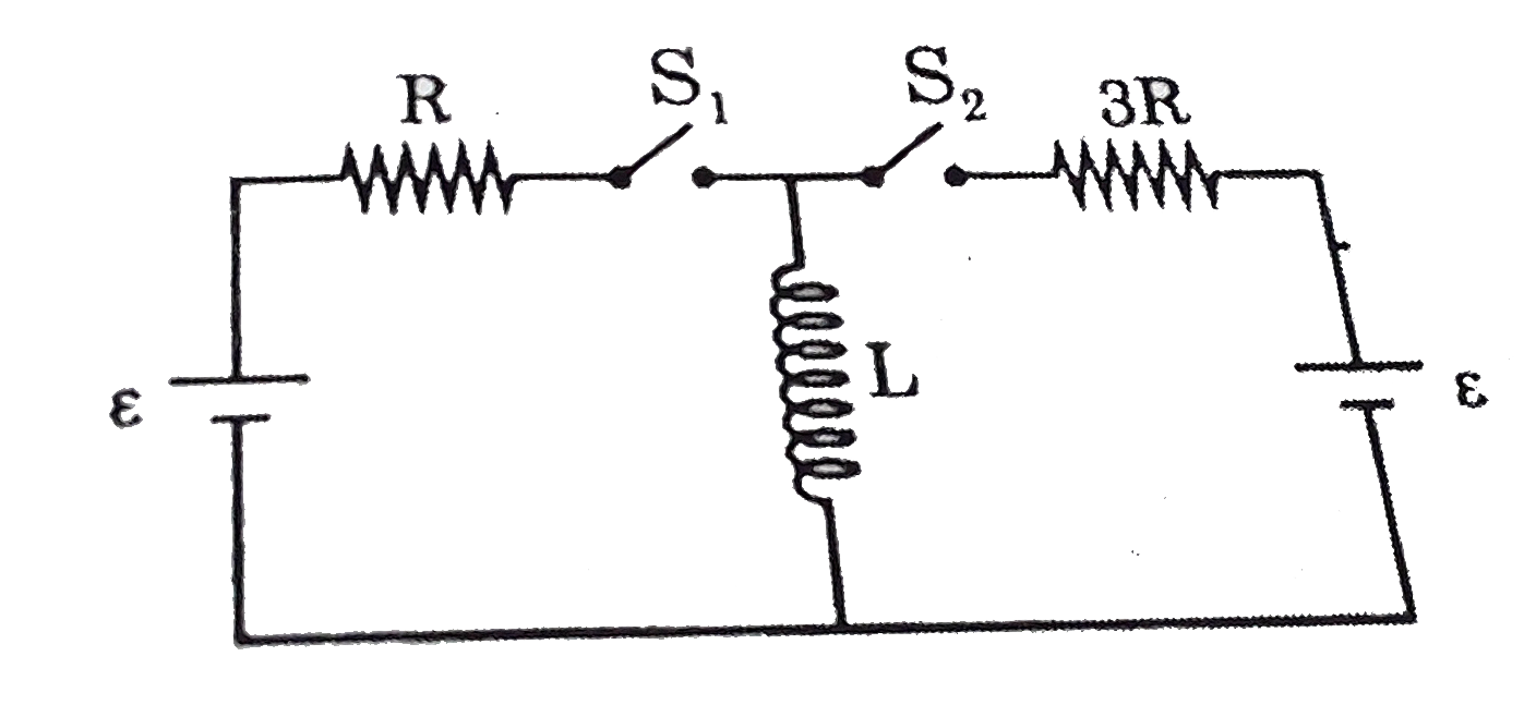
Current passing through R just after S1 is closed , is :
View SolutionIn the given circuit switch S2 is Kept closed and S1 is kept open for a very long time such that the system is in steady- state . Now S1 is also slosed keeping S2 closed.
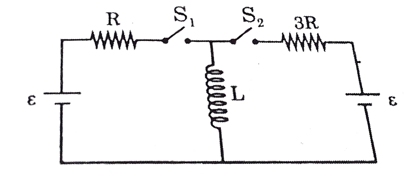
Current passing through inductor L time after S1 is closed , is :
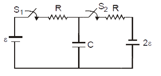
View SolutionAt t=0 switch S1 is closed and remains closed for a long time and S2 remains open. Now S1 is opened and S2 is closed. Find out
(i) The current through the capacitor immediately after that moment
(ii) Charge on the capacitor long after that moment.
(iii) Total charge flown through the cell of emf 2ε after S2 is closed.
View SolutionAt t =0 switch S1 is closed and remains closed for a long time and S2 remains open. Now S1 is opened and S2 is closed. Find out
The current through the capacitor immediately after that moment
View SolutionWhen the switch S is closed in the given circuit, the current passed through it is

View Solution
