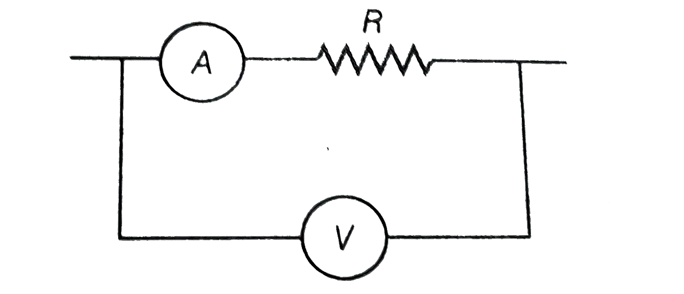
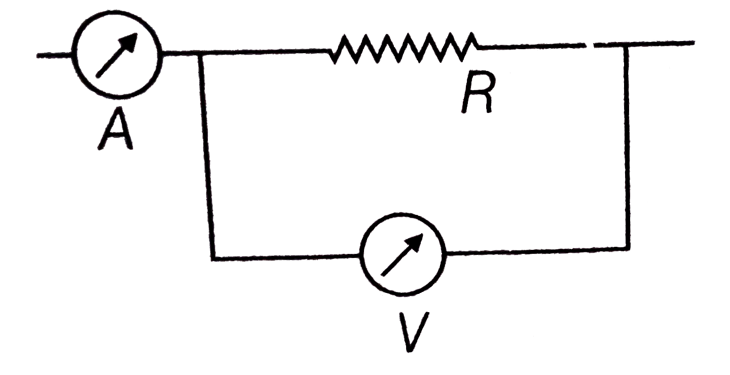
In the circuit shown the reading of ammeter and voltmeter are 4A and 20V respectively. The meters are non ideal, then R ia

A
5Ω
B
less than 5Ω
C
greater than 5Ω
D
between 4Ω and 5Ω
Video Solution
Text Solution
The correct Answer is:C
(c ) Measured value of R=VI=204=5Ω
But current in R will acturally be less than I, so R should be greater than 5Ω.
|
Updated on:21/07/2023
Topper's Solved these Questions
- BOOK - A2ZCHAPTER - CURRENT ELECTRICITYEXERCISE - Potentiometer And Meter Bridge45videos
CURRENT ELECTRICITY
- BOOK - A2ZCHAPTER - CURRENT ELECTRICITYEXERCISE - Heating Effect Of Current40videos
CURRENT ELECTRICITY
- BOOK - A2ZCHAPTER - CURRENT ELECTRICITYEXERCISE - R-C Circuits17videos
CURRENT ELECTRICITY
- BOOK - A2ZCHAPTER - ATOMIC PHYSICSEXERCISE - Section D - Chapter End Test30videos
ATOMIC PHYSICS
- BOOK - A2ZCHAPTER - DUAL NATURE OF RADIATION AND MATTEREXERCISE - Section D - Chapter End Test30videos
DUAL NATURE OF RADIATION AND MATTER
Similar Questions
Knowledge Check
- Question 1 - Select One
In the circuit shown here, the readings of the ammeter and voltmeter are
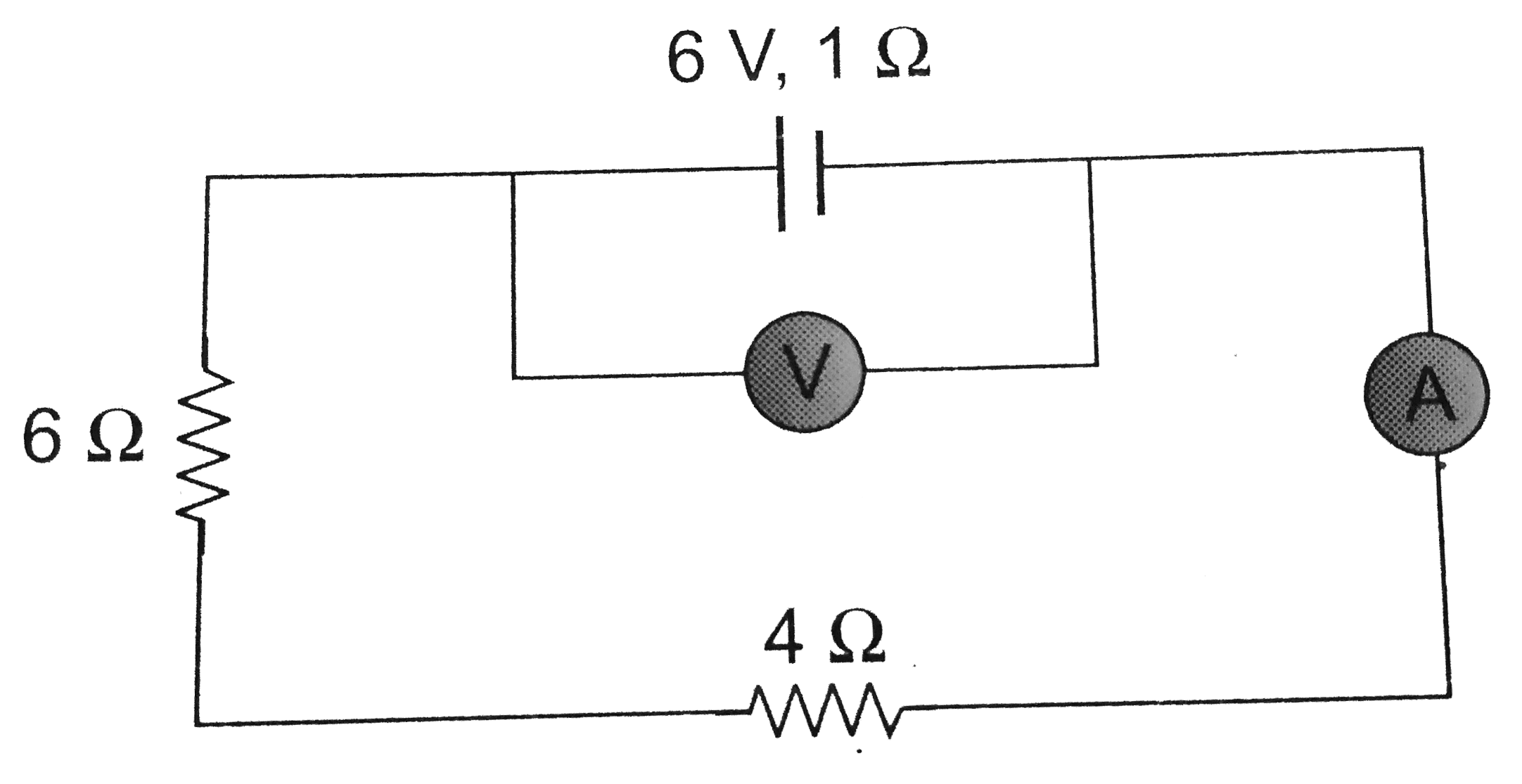 A6A,60VB0.6A,6VC6/11A,60/11VD11/6A,11/60V
 - Question 2 - Select One
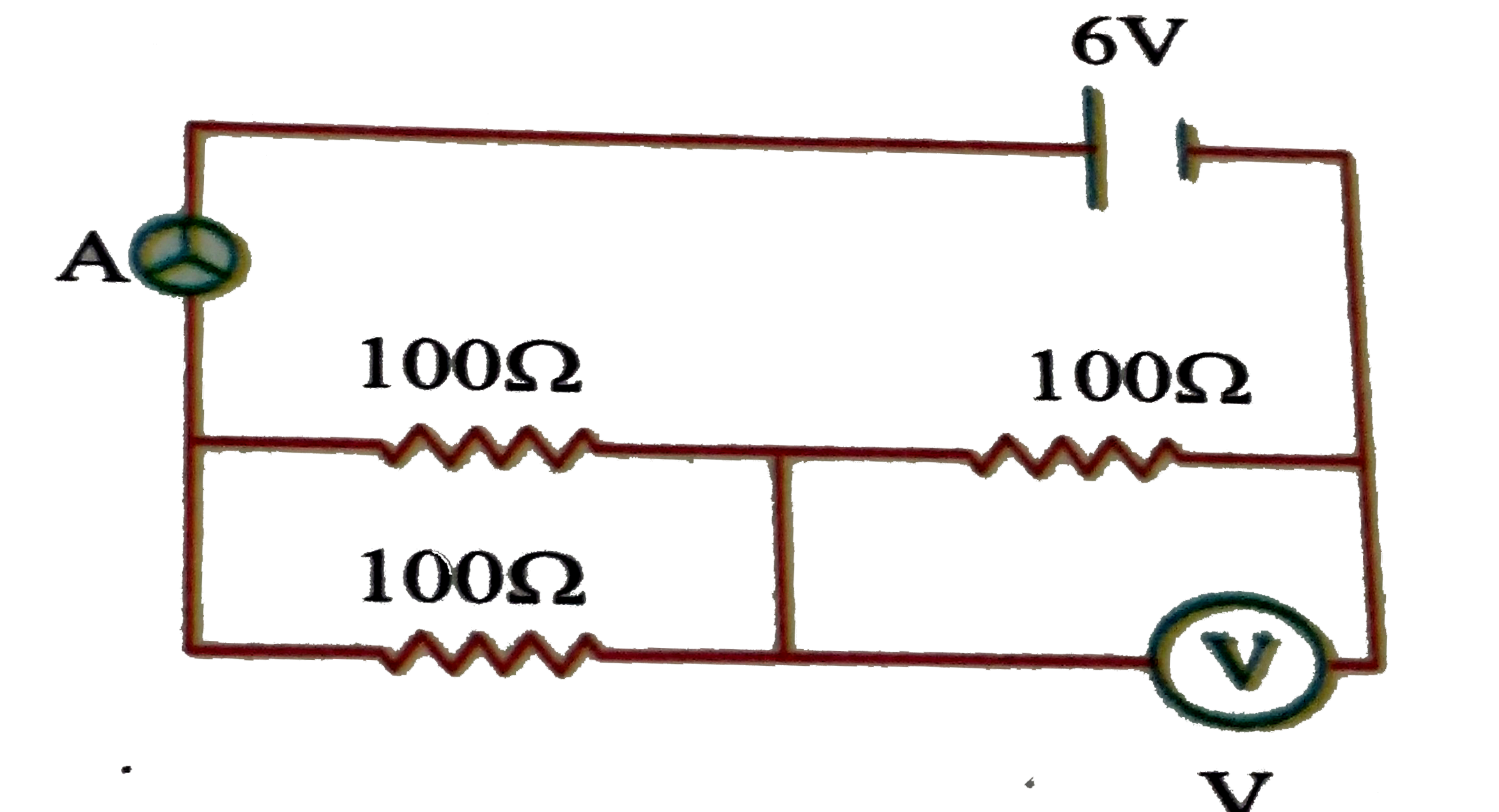
In the circuit shown, the reading of the voltmeter and the ammeter areA4V.0.2AB2V,0.4AC3V,0.6AD4V,0.04A - Question 3 - Select One
For the AC circuit shown, the reading of ammeter and voltmeter are 5A and 50√5 volts respectively, then
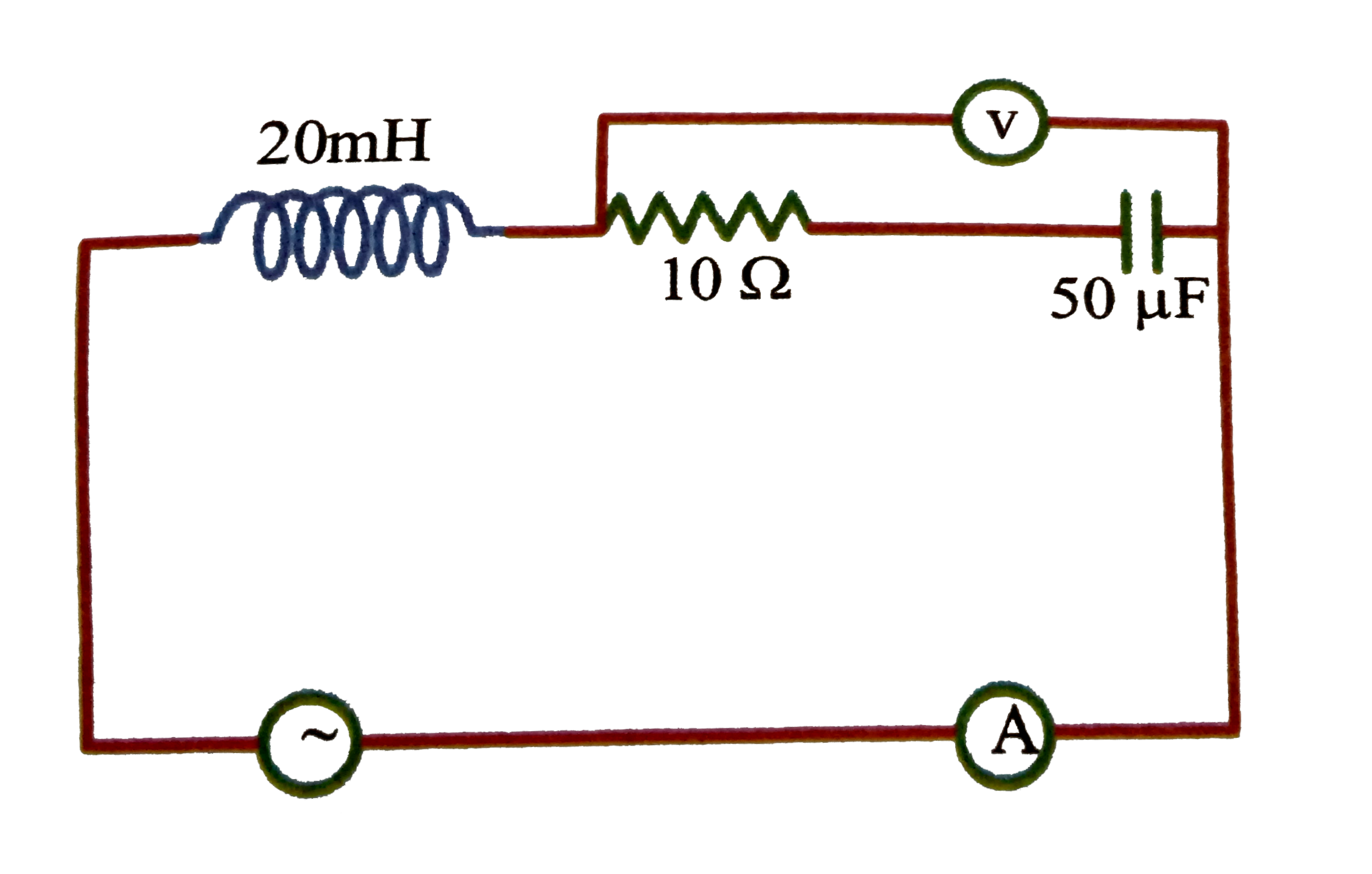 Aaverage power deliverd by the source is 250WBrms value of AC source is 50 voltsCvoltage gain is 2Dfrequency of ac source is 1000rad/s
In the adjoining circuit diagram, the readings of ammeter and voltmeter are 2 A and 120 V, respectively. If the value of R is 75Ω, then the voltmeter resistance will be
 View Solution
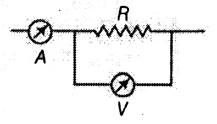
For the adjoining circuit diagram, the readings of ammeter and voltmeter are 2A and 120 V respectively. If the value of R is 75Ω, then the voltmeter resistance will be
 View Solution
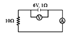
Find the readings of the ammeter (A) and voltmeter (V):
 View Solution
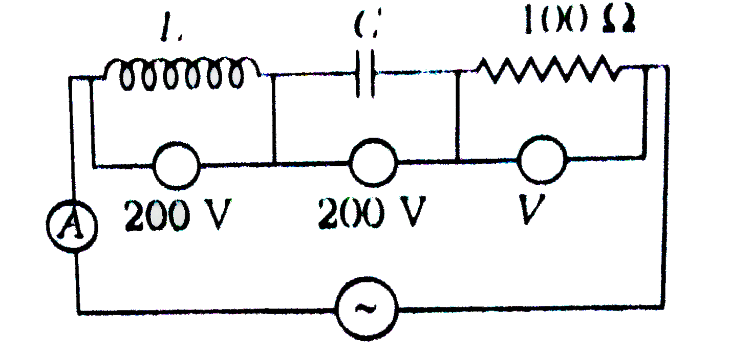
The reading of ammeter and voltmeter in the following circuit are respectively
 View Solution
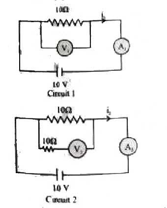
In the circuits shown below, the readings of the voltmeters and the ammeters will be
 View Solution


