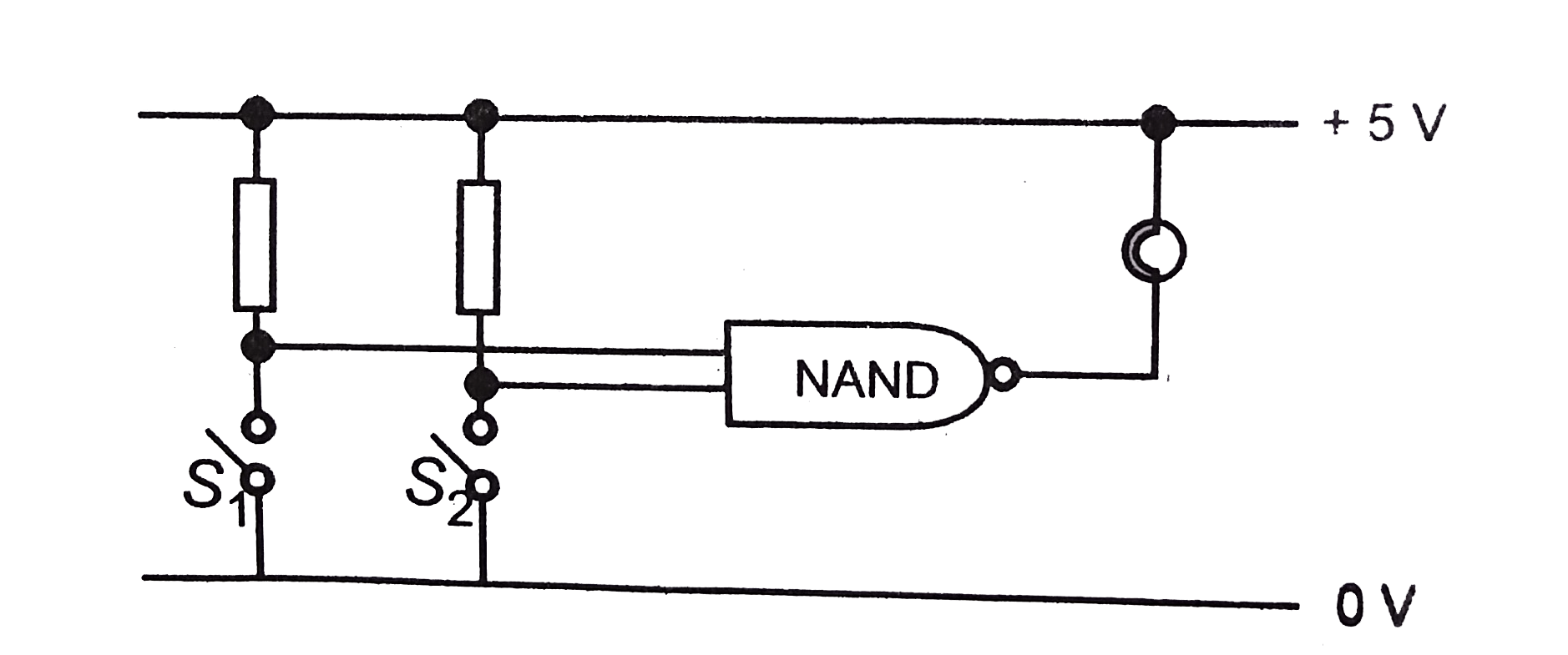
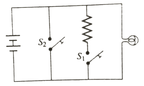
Figure shows a circuit designed to control a lamp. For what positions of the switches and will the lamp the lit?
The correct Answer is:D
The truth table of the gate is as shown below:
Where a level at the input, or corresponds to a closed switch (at ) and a logic level at the output means the lamp will be lit. From the truth table, both switches and have to be at open position in order to light up the lamp at the output of the gate.
Topper's Solved these Questions
- SEMICONDUCTOR ELECTRONICSBOOK - A2ZCHAPTER - SEMICONDUCTOR ELECTRONICSEXERCISE - Section B - Assertion Reasoning
22 Videos
- SEMICONDUCTOR ELECTRONICSBOOK - A2ZCHAPTER - SEMICONDUCTOR ELECTRONICSEXERCISE - AIPMT/NEET Questions
77 Videos
- SEMICONDUCTOR ELECTRONICSBOOK - A2ZCHAPTER - SEMICONDUCTOR ELECTRONICSEXERCISE - Digital Electronics
40 Videos
- NUCLEAR PHYSICSBOOK - A2ZCHAPTER - NUCLEAR PHYSICSEXERCISE - Section D - Chapter End Test
29 Videos
- SOURCE AND EFFECT OF MAGNETIC FIELDBOOK - A2ZCHAPTER - SOURCE AND EFFECT OF MAGNETIC FIELDEXERCISE - Section D - Chapter End Test
30 Videos
Similar Questions
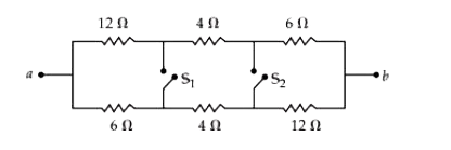
In the given figure switches S1andS2 are in open condition. The resistance across ab when the switches S1andS2 are closed is ……………… Ω.
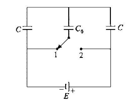
View SolutionFigure shows a circuit with three capacitors connected with a battery. What amount of heat will be generated in the circuit when the switch S is shifted from position 1 to 2.
View Solution
Knowledge Check
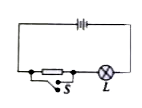
The given figure shows an electric circuit in which a lamp L is connected .What happens to the brightness of the lamp L when the switch S is closed ?
(Box represents extra resistance in the circuit.)
 AIt becomes dimmerBIt becomes brighter .CIt goes off .DIt remains the same .
Figure shows four plates each of plate area A and separated between plates is d. Two switches Sw1andSw2 can activate two batteries in the circuit.
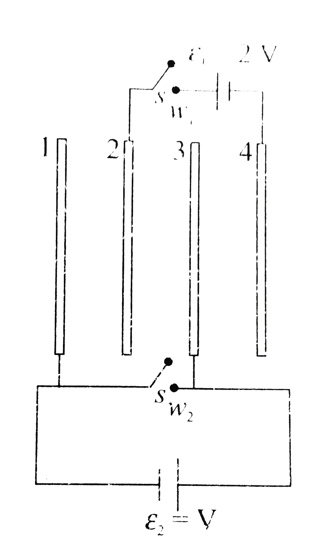
Switch Sw1andSw2 are closed, What is the charge on plate 2?A32ε0AVDB32ε0AVdC13ε0AVdD43ε0AVdIn the given circuit, the initial charges on the capacitors are shown in the figure. The charge flown through the switches S1andS2 respectively after closing the switches are
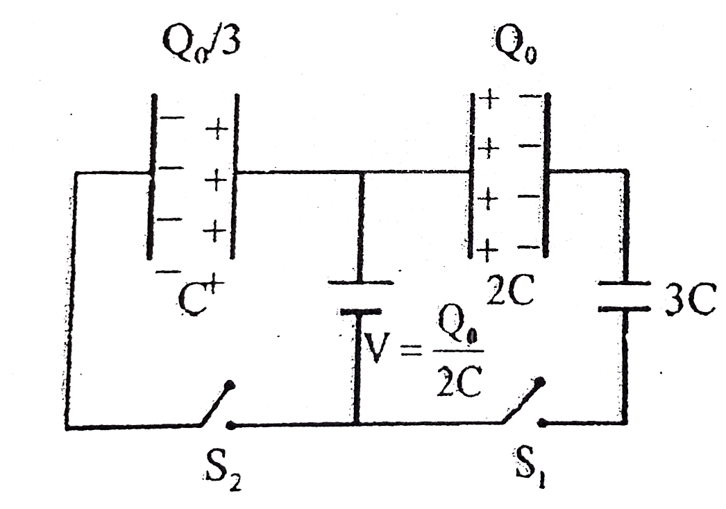 AzeroQ06BQ05,Q02Czero,Q02D35Q0,Q06
Using the circuit given below, state which of the following statemet is correct?
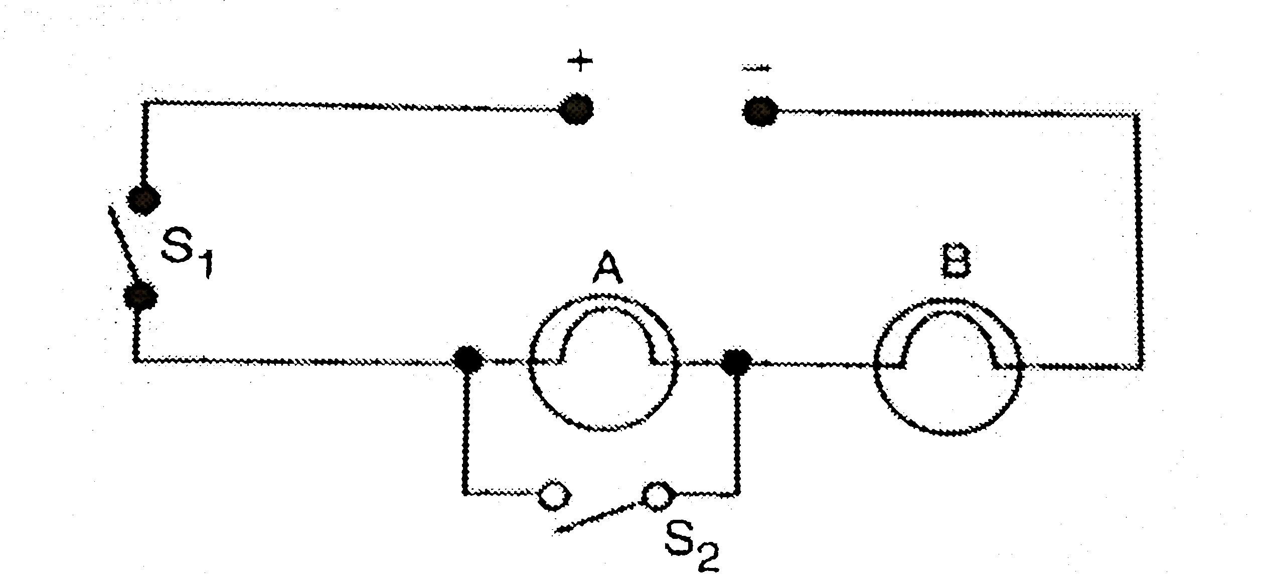
(a) When S1 and S2 are closed, lamps A and B are lit.
(b) With S1 open and S2 closed, A is lit and B is not lit.
(c) With S2 open and S1 closed A and B are lit.
(d) With S1 closed and S2 open, lamp A remains lit even if lamp B gets fused.
View SolutionFigure shows four plates each of plate area A and separated between plates is d. Two switches Sw1andSw2 can activate two batteries in the circuit.
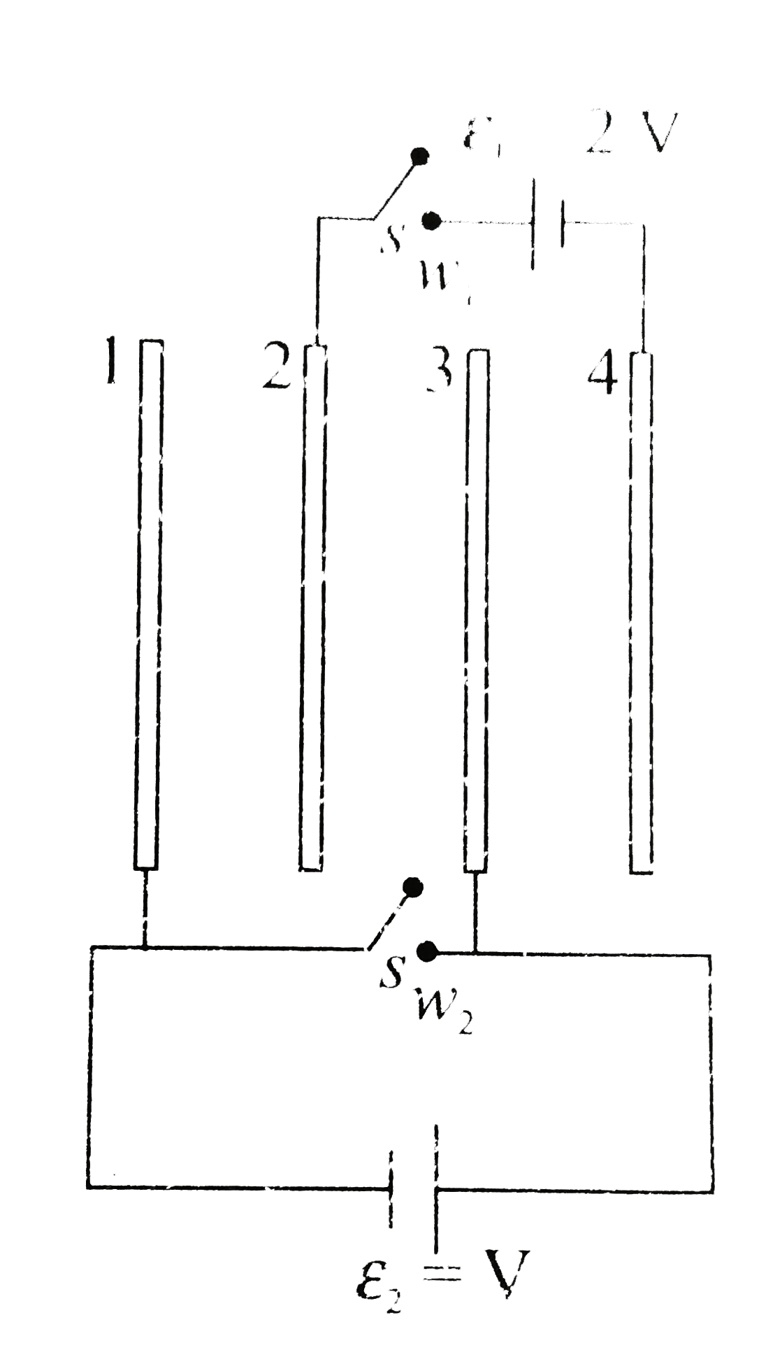
Now switch Sw2 is opened, what is the charge on plate 4?
View SolutionFigure shows four plates each of plate area A and separated between plates is d. Two switches Sw1andSw2 can activate two batteries in the circuit.
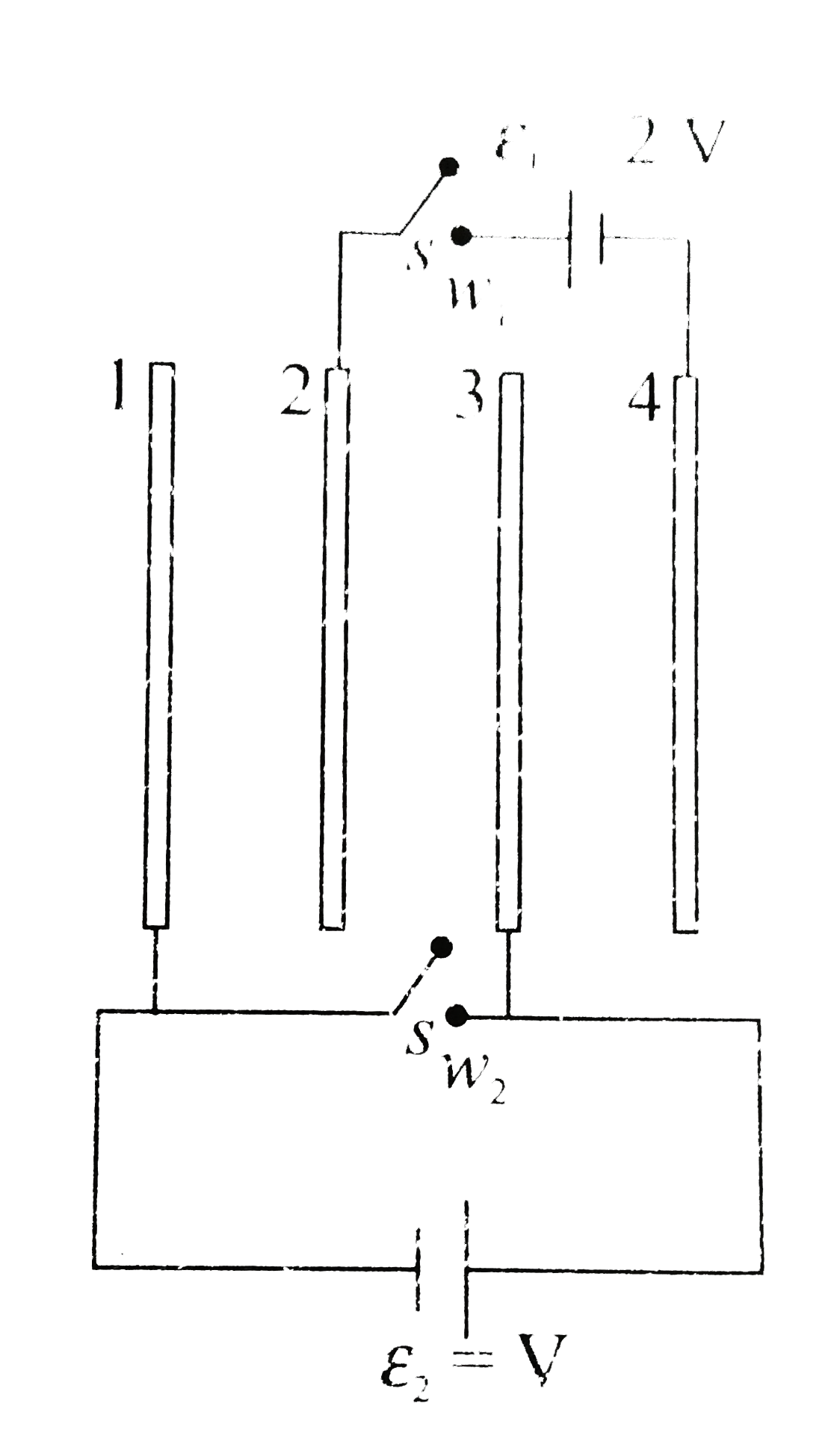
What is the charge passing through battery 1?
View SolutionWhich of two switches S1andS2 shown in Fig. 7.31 will produce short - circuiting?
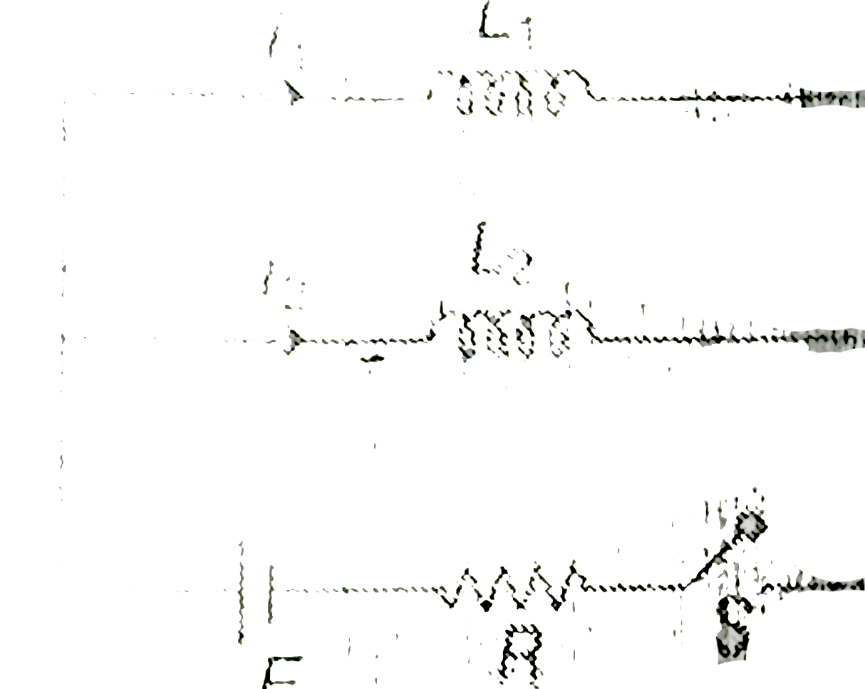
View SolutionIn the circuit shown in the figure The steady state currents i1andi2 in the coils after the switch S is closed are
View Solution
