The function of a half -adder may be represented as shown in Figure.

A full-adder may be constructed from two half-adders together with a single logic gate as shown in figure.

Which logic gate must be used?
A
AND
B
EX−NOR
C
HAND
D
OR
Text Solution
The correct Answer is:D
When three bits is to be added, a full-adder may be constructed form two half-adders together with a single logic gate of OR.
|
Topper's Solved these Questions
- SEMICONDUCTOR ELECTRONICSBOOK - A2ZCHAPTER - SEMICONDUCTOR ELECTRONICSEXERCISE - Section B - Assertion Reasoning
22 Videos
- SEMICONDUCTOR ELECTRONICSBOOK - A2ZCHAPTER - SEMICONDUCTOR ELECTRONICSEXERCISE - AIPMT/NEET Questions
77 Videos
- SEMICONDUCTOR ELECTRONICSBOOK - A2ZCHAPTER - SEMICONDUCTOR ELECTRONICSEXERCISE - Digital Electronics
40 Videos
- NUCLEAR PHYSICSBOOK - A2ZCHAPTER - NUCLEAR PHYSICSEXERCISE - Section D - Chapter End Test
29 Videos
- SOURCE AND EFFECT OF MAGNETIC FIELDBOOK - A2ZCHAPTER - SOURCE AND EFFECT OF MAGNETIC FIELDEXERCISE - Section D - Chapter End Test
30 Videos
Similar Questions
Knowledge Check
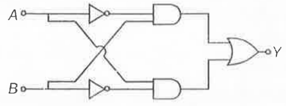
The combination of the gates as shown in figure represent
 AOR gateBAND gateCNOR gateDXOR gate
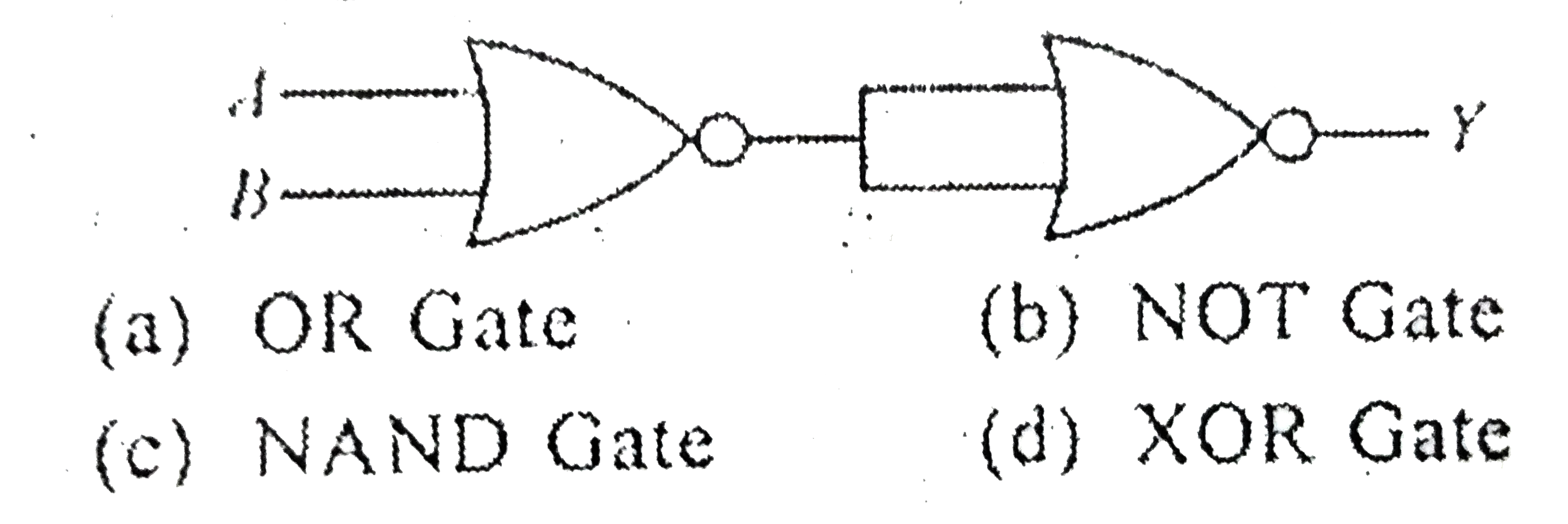
The logic gate represented in following figure is
 AOR GateBNOT GateCNAND GateDXOR Gate
The output Y of the logic circuit as shown in figure is best represents as
 A¯¯¯A+¯¯¯¯¯¯¯¯¯B⋅CBA+¯¯¯B⋅CC¯¯¯¯¯¯¯¯¯¯¯¯¯¯¯¯¯A+B⋅CD¯¯¯¯¯¯¯¯¯¯¯¯¯¯¯¯¯A+¯¯¯B⋅C
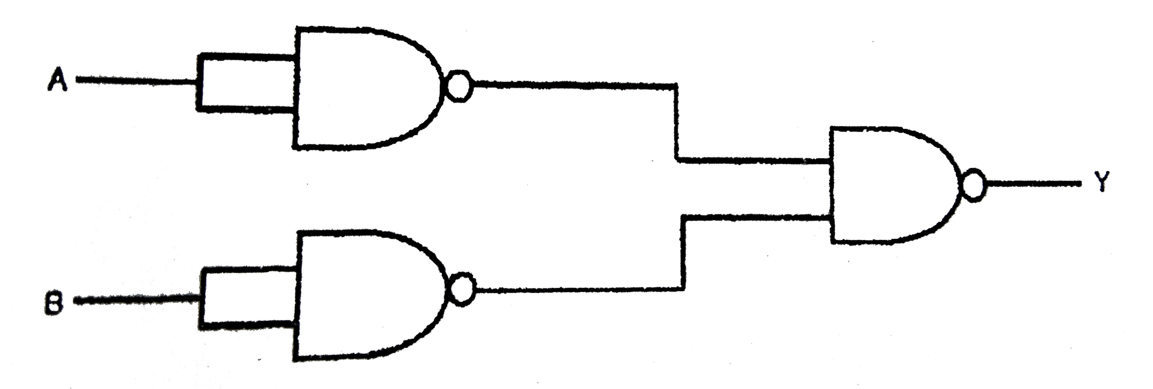
The logic circuit (figure) represents which logic gate?

View SolutionThe logic circuit (figure) represents which logic gate?

View SolutionThe logic gate represented in following figure is

View SolutionLogic gate realised from pn Junctions shown in figure is
View Solution
Name of gate obtained from the combination of gates shown in the figure. Draw its logic symbol. Write the truth table of the combination.
View Solution

