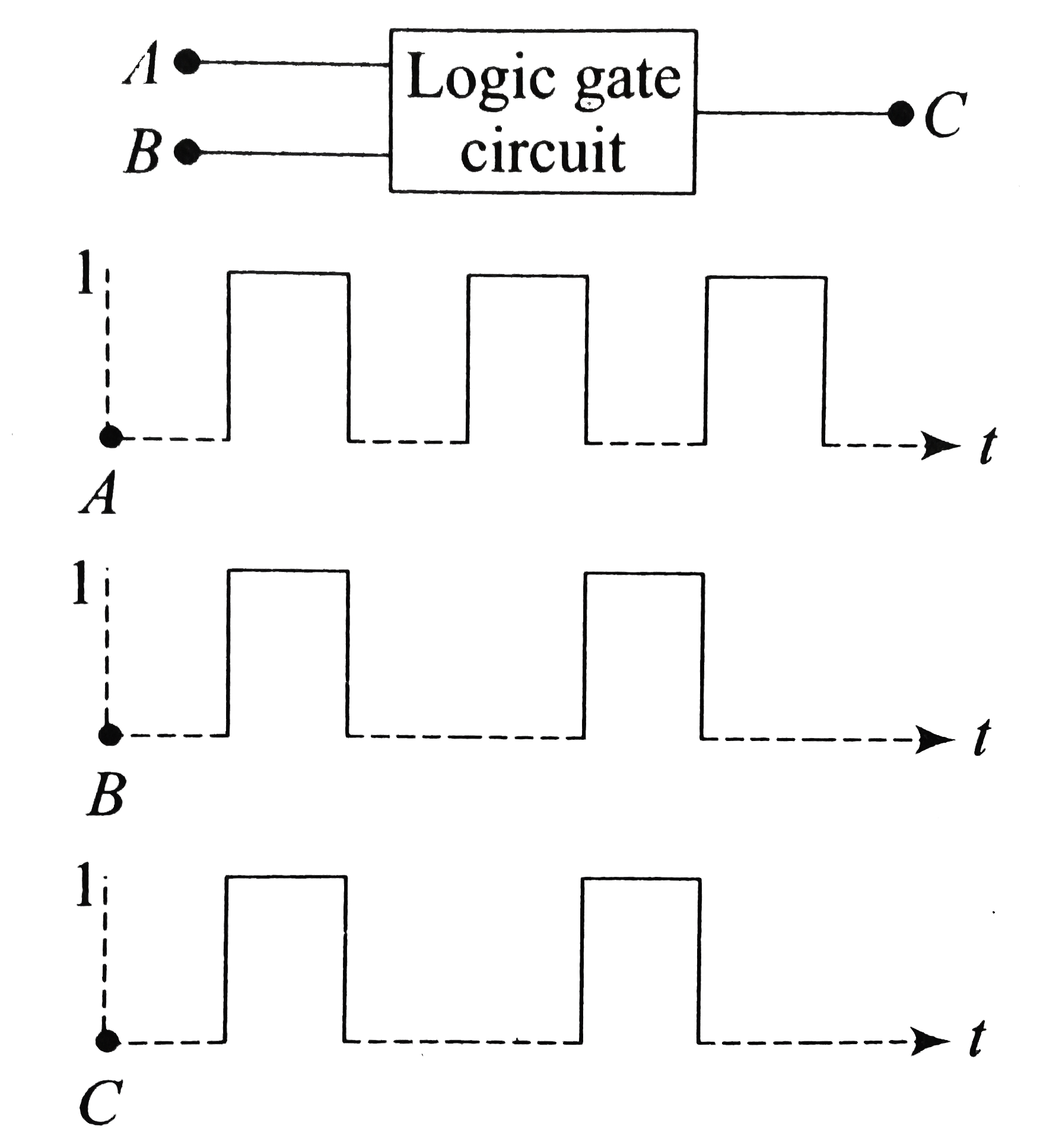
The following figure shows a logic gate circuit with two inputs A and B and the output C. The voltage waveforms of A,B and C are as shown below
AND gate
NAND gate
NOR gate
OR gate
The correct Answer is:A
The Boolean expression which satisfies the output of this logic gate is C=A.B,which is for AND gate.
Topper's Solved these Questions
- BOOK - A2ZCHAPTER - SEMICONDUCTOR ELECTRONICSEXERCISE - AIIMS Questions38videos
SEMICONDUCTOR ELECTRONICS
- BOOK - A2ZCHAPTER - SEMICONDUCTOR ELECTRONICSEXERCISE - Assertion Reason18videos
SEMICONDUCTOR ELECTRONICS
- BOOK - A2ZCHAPTER - SEMICONDUCTOR ELECTRONICSEXERCISE - Section B - Assertion Reasoning22videos
SEMICONDUCTOR ELECTRONICS
- BOOK - A2ZCHAPTER - NUCLEAR PHYSICSEXERCISE - Section D - Chapter End Test29videos
NUCLEAR PHYSICS
- BOOK - A2ZCHAPTER - SOURCE AND EFFECT OF MAGNETIC FIELDEXERCISE - Section D - Chapter End Test30videos
SOURCE AND EFFECT OF MAGNETIC FIELD
Similar Questions
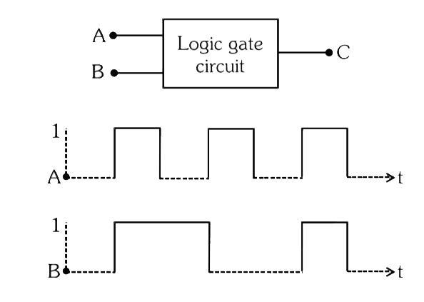
The following figure showns a AND logic gate circuit with two inputs A and B and the output C. The voltage waveforms at C will be -
 View Solution
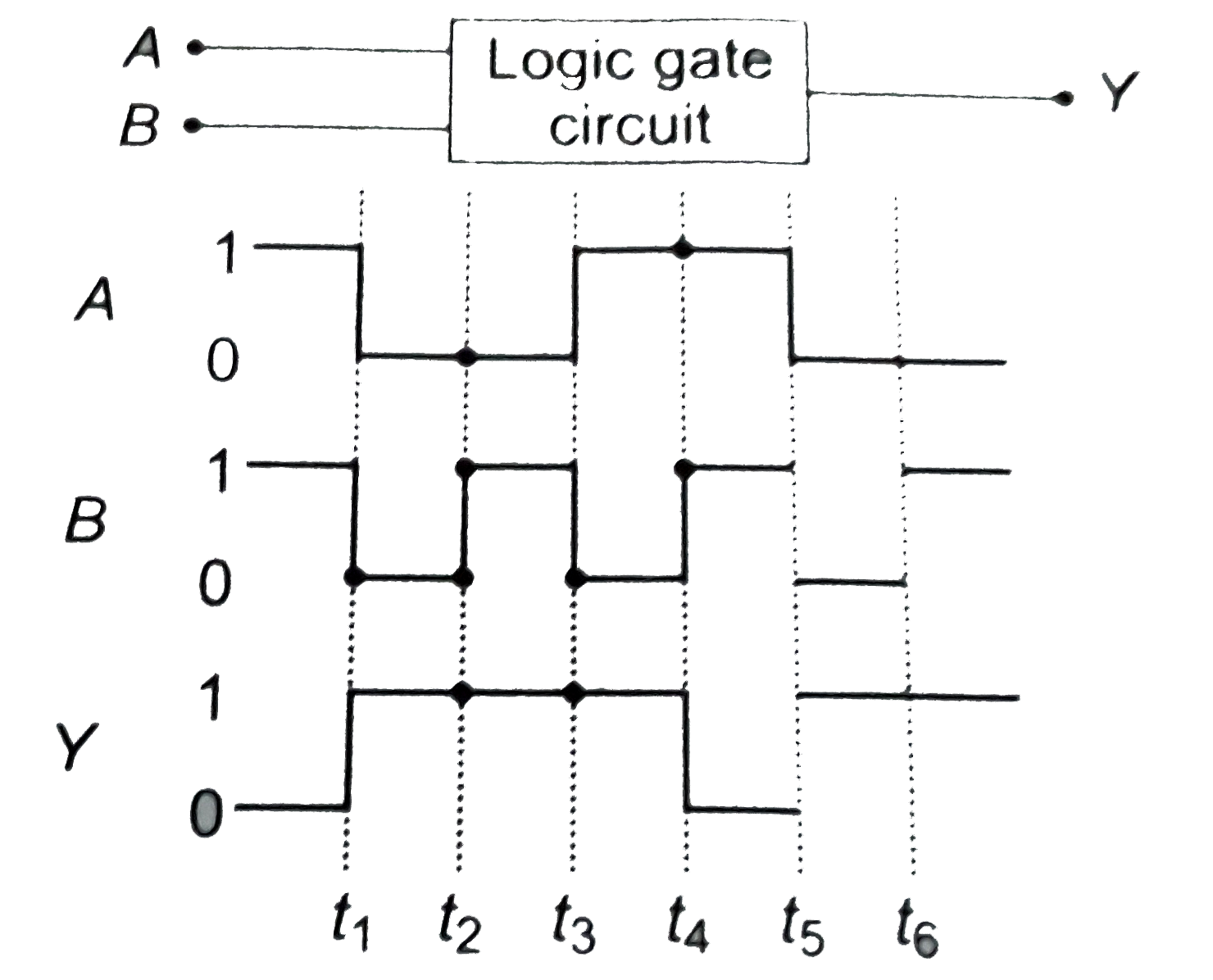
The following figure shows a logic gate circuit with two inputs A and B and the output Y. The voltage waveforms of A,B and the output Y are as given
 View Solution
Knowledge Check
- Question 1 - Select One
The following shows a logic gate circuit with two inputs A and B and the output C. The voltage waveforms of A, B and C are as shown below.
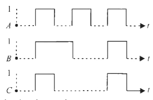
The logic circuit gate isAOR gateBAND gateCNAND gateDNOR gate - Question 2 - Select One
The following figure shows a logic gate circuit with two inputs A and B and the output Y. The voltage waveforms of A,B and the output Y are as given
 ANOR gateBOR gateCAND gateDNAND gate
 - Question 3 - Select One
The following figure shows a logic gate circuit with two inputs A and B and the output Y. The voltage waveforms of A,B and Y are as given :
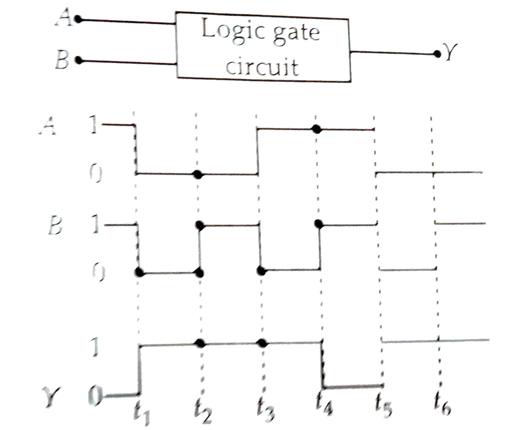
The logic gate isANOR gateBOR gateCAND gateDNAND gate
The following figure shows a logic gate circuit with two inputs A and B output C. The voltage waveforms of A,B and C are as shown in second figure given below :-
_E01_436_Q01.png)
The logic circuit gate is :-View SolutionFig, shows a logic gate circuit with two input A and B and the output C. The voltage wave form of A, B and C are as shown in Fig.The logic gate circuit is
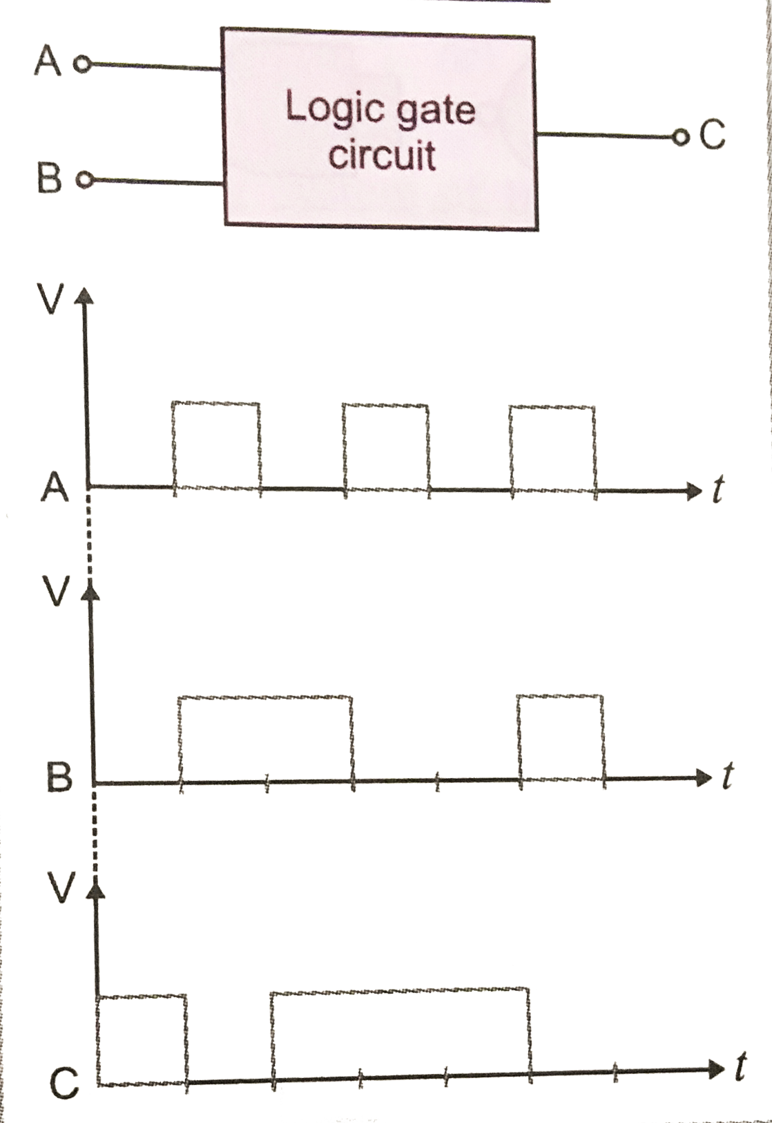 View Solution
The figure shows a logic circuit with two inputs A and B and the output C. The voltage wave forms across A,B and C are as given. The logic circuit gate is
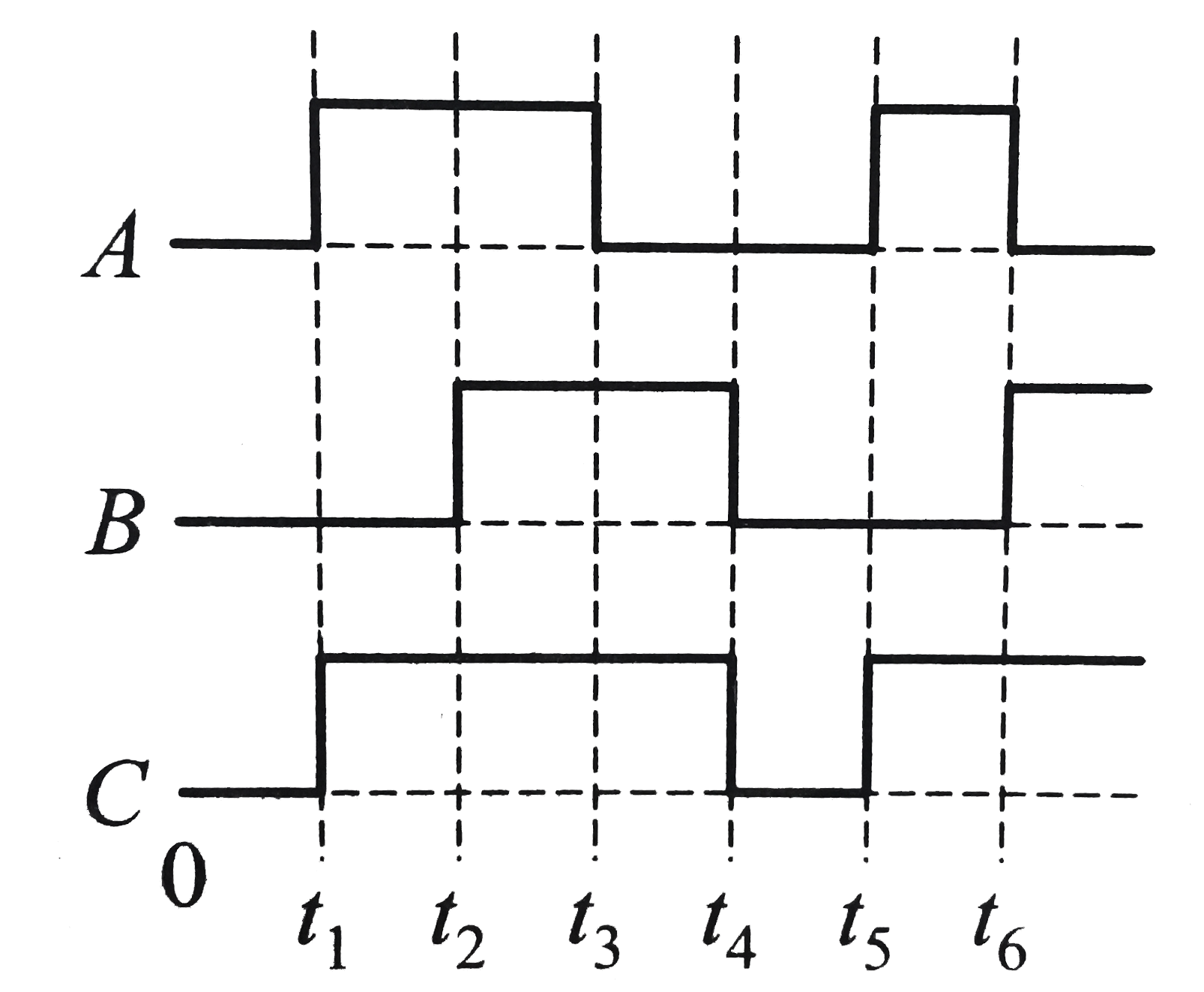 View Solution
The figure shows a logic circuit with two inputs A and B and the output C. The voltage wave forms across A,B and C are as given. The logic circuit gate is
 View Solution
The Fig.shows a logic gate circuit with two inputs A and B and the output C are as shown in Fig.
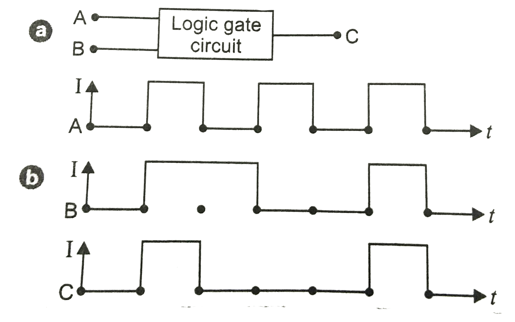 View Solution

