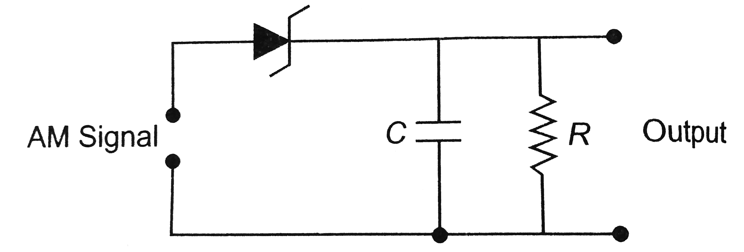
Given below a circuit diagram of an AM demodulator.

For good demodulation of AM signal of carrier frequency f, the value of RC should be:
RC=1f
RC<1f
RC≥1f
RC>>1f
The correct Answer is:d
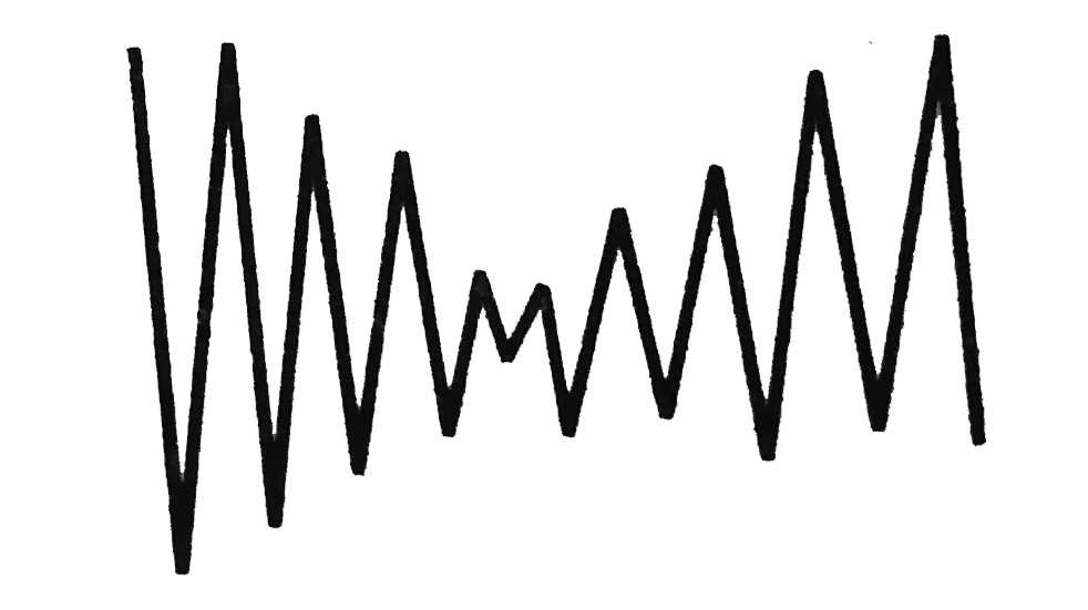
From the modulated signal, we can demodulate or detect the modulating or message signal by using a diode and suitable capacitor filter. The AM signal given to the input of the circuit appears at output of the diode as a rectified wave as shown

For good demodulation of AM signal the value of RC (which is a time-constant) is chosen such that
1F<<RC or RC>>1f
where f is the frequency of the carrier signal.
Topper's Solved these Questions
- MOCK TESTBOOK - A2ZCHAPTER - MOCK TESTEXERCISE - Mock Test 2
45 Videos
- MOCK TESTBOOK - A2ZCHAPTER - MOCK TESTEXERCISE - Mock Test 3
44 Videos
- MAGNETISM AND MATTERBOOK - A2ZCHAPTER - MAGNETISM AND MATTEREXERCISE - Section D - Chapter End Test
30 Videos
- NUCLEAR PHYSICSBOOK - A2ZCHAPTER - NUCLEAR PHYSICSEXERCISE - Section D - Chapter End Test
29 Videos
Similar Questions
Knowledge Check
Fig. 10 (CF).1 is the circuit diagram of an AM demondulator. For good demodulation of AM signal of carrier frequency f, the value of RC should be
 ARC=1/fBRC<1/fCRC≤1/fDRC>>1/f
In the given detector circuit, the suitable value of carrier frequency is
 A<<109HzB<<105HzC>>109HzDNone of these
In an AM wave for audio frequency of 3400 cycle/s, the appropriate carrier frequency will be
A1000 HzB34000 MHzC60000 HzD800,000 Hz
If Am and Acare the amplitudes of modulating signal and carrier wave respectively, then modulation index is given by
View SolutionWhat is the modulation index if an audio signal of amplitude one half of the carrier amplitude is used in AM?
View SolutionIf Am and Acare the amplitudes of modulating signal and carrier wave respectively, then modulation index is given by
View SolutionA message signal m(t)=4cos2000πt modulates the carrier C(t)=cos2πfct where fc=1MHz to produce an AM signal. For demodulation using envelope detector the time constant RC should satisfy
View SolutionOne of the components of frequency of amplitude modulated wave (AM) formed by the superposition of message signal of frequency ω1 on a carrier wave of frequency ω2 is
View Solution
