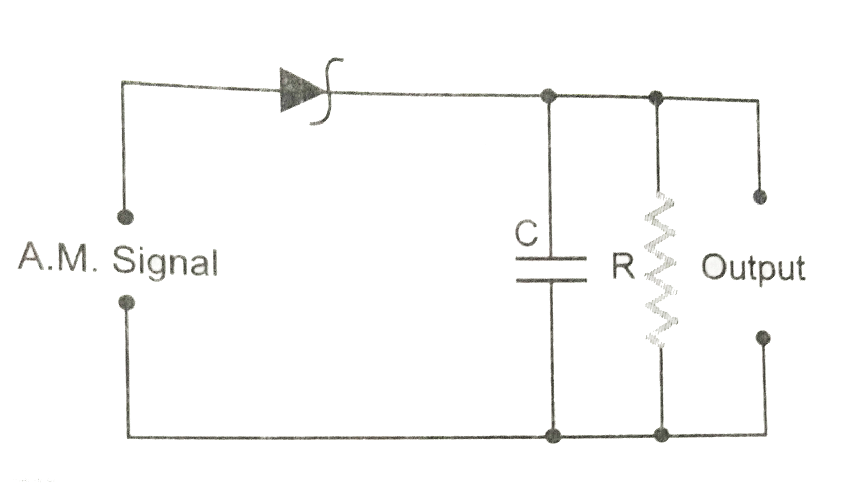
Fig. 10 (CF).1 is the circuit diagram of an AM demodulator. For good demodulation of AM signal of carrier frequency f, the value of RC should be

RC=1/f
RC<1/f
RC≥1/f
RC>>1/f
The correct Answer is:D
For good demdulation.
1f<<RC.orRC>>1f.
Similar Questions
A bat moving at 10ms−1 towards a wall sends a sound signal of 8000 Hz towards it. On reflection it hears a sound of frequency f. The value of g in Hz is close to (speed to sound =320ms−1) :
View SolutionBoth amplitude modulation (AM) and frequency modulation (FM) are used for radio broadcasting. The amplitude of the high frequency carrier wave is varied or modulated in accordance with the variations in the amplitude of the audio signals that are to be transmitted, in te process of amplitude modulation in frequency modulation te amplitude of the carrier remains constant but its frequency is varied inn accordance withh the audio signal. Reception with AM signals is in general is affected by interference of various kinds ad elaborated equipment is required for FM broadcast.
In india the radio signals are boarcast using-
View Solution
Knowledge Check
A message signal of freuency ωm is superposed on a carrier wave of frequency ωc to get an amplititude modulated wave (AM). The frequency of the AM wave will be
AωmBωcCωc+ωm2Dωc−ωm2A message signal of freuency ωm is superposed on a carrier wave of frequency ωc to get an amplititude modulated wave (AM). The frequency of the AM wave will be
AωmBωcCωc+ωm2Dωc−ωm2
Both amplitude modulation (AM) and frequency modulation (FM) are used for radio broadcasting. The amplitude of the high frequency carrier wave is varied or modulated in accordance with the variations in the amplitude of the audio signals that are to be transmitted, in te process of amplitude modulation in frequency modulation te amplitude of the carrier remains constant but its frequency is varied inn accordance withh the audio signal. Reception with AM signals is in general is affected by interference of various kinds ad elaborated equipment is required for FM broadcast.
The rangeof a transmitter is
View SolutionA carrier frequency of 1 MHz and peak value of 10 V is amplitude modulated with a signal frequency of 10 KHz with peak value of 0.5 V. What are the values of the modulation index and the side band frequencies ?
View Solution(a) Draw a schematic diagram of an AC generator. Explain is working and obtain the expression for the instantaneous value of the emf in terms of the magnetic field B, number of turns N of the coil of area A rotating with angular frequency ω. Show how an alternating emf is generated by loop of wire rotating in a magnetic field.
(b) A circular coil of radius 10 cm and 20 turns is rotated about its vertical diameter with angular speed of 50 rad s−1. in a uniform horizontal magnetic field of 3.0×10⁻²T.
(i) Calculate the maximum and average emf induced in the coil.
(ii) If the coil forms a closed loop of resistance 10Ω, calculate the maximum current in the coil and the average power loss due to Joule heating.
View SolutionA message signal of freuency ωm is superposed on a carrier wave of frequency ωc to get an amplititude modulated wave (AM). The frequency of the AM wave will be
View SolutionA message signal of freuency ωm is superposed on a carrier wave of frequency ωc to get an amplititude modulated wave (AM). The frequency of the AM wave will be
View SolutionOne of the components of frequency of amplitude modulated wave (AM) formed by the superposition of message signal of frequency ω1 on a carrier wave of frequency ω2 is
View Solution
