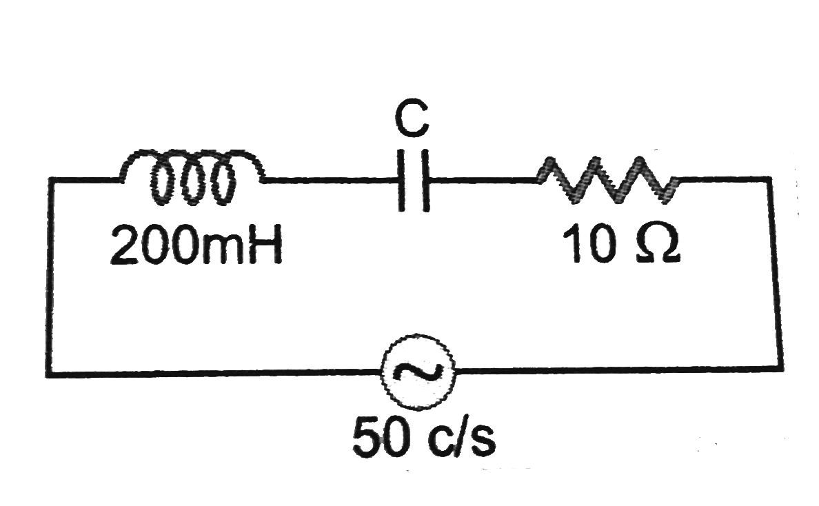
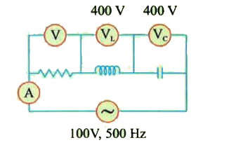
In the circuit shown in fin. Calculate the capacitance C of the capacitor, if the power factor of the circuit is unity. Also, calculate Q factor of the circuit.
Video Solution
Text Solution
Here, C=?,
Power factor, cosϕ=RZ=1
∴Z=R∴XC=XL,12πvC=2πvL
C=14π2v2L=14(3.14)2(50)2×200×10−3
=5×10⁻⁵f=50μF
Q factor =12√LC=110√200×10−350×10−6=6.32
|
Topper's Solved these Questions
- ELECTROMAGNETIC INDUCTION & ALTERNATING CURRENTBOOK - PRADEEPCHAPTER - ELECTROMAGNETIC INDUCTION & ALTERNATING CURRENTEXERCISE - Solved Examples (b)
1 Videos
- ELECTROMAGNETIC INDUCTION & ALTERNATING CURRENTBOOK - PRADEEPCHAPTER - ELECTROMAGNETIC INDUCTION & ALTERNATING CURRENTEXERCISE - Short Answer Qusetions
2 Videos
- DUAL NATURE OF RADIATION AND MATTERBOOK - PRADEEPCHAPTER - DUAL NATURE OF RADIATION AND MATTEREXERCISE - Exercise
191 Videos
- ELECTROMAGNETIC WAVESBOOK - PRADEEPCHAPTER - ELECTROMAGNETIC WAVESEXERCISE - II Focus multiple choice question
5 Videos
Similar Questions
In the circuit shown in Fig. 7.41, calculate
(a) the capacitance of the capacitor if the power factor of the circuit is unity, and
(b) the Q-factor of the circuit. Given that the angular frequency of the a.c. source is 100s−1 .
(C) Also calculate the average power dissipated in the circuit.
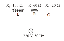
View SolutionWhat is the power factor for the circuit shown ?
View Solution
Knowledge Check
The power factor of a circuit is
AZ/RBR/ZCR/XDX/RThe power factor of L-R circuit is-
AωLRBR√(ωL)2+R2CωLRD√ωLRIf the power factor in a circuit is unity, then the impedance of the circuit is
AinductiveBcapacitiveCpartially inductive and partially capacitiveDresistive
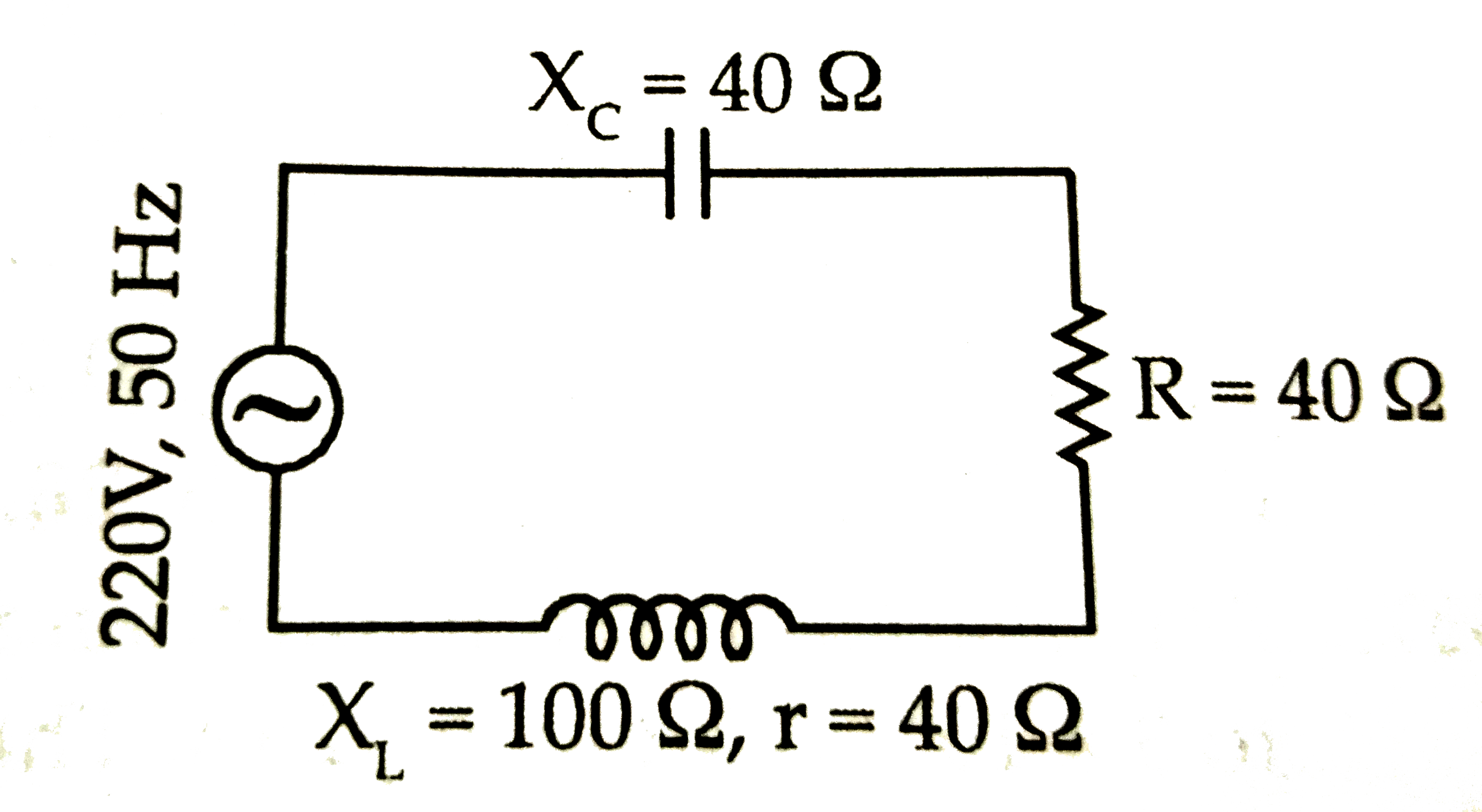
The power factor of the circuit shown in figure is
View SolutionThe power factor for the circuit shown below is
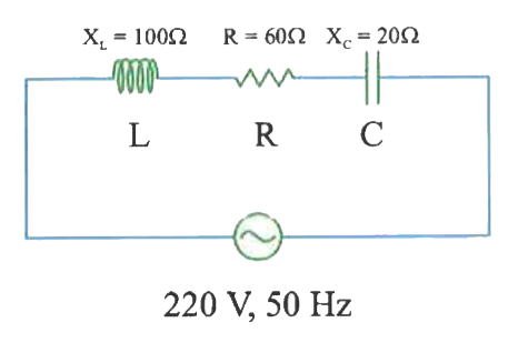
View SolutionThe power factor for the circuit shown below is

View SolutionFind the power factor of the circuit shown in figure.
View SolutionFind the power factor of the circuit shown in figure.

View Solution
