Altering current through pure, inductor and pure capacitor is wattless
Step-by-Step Solution:
1. Understanding Wattless Power:
- Wattless power refers to the condition where no active power is consumed in an electrical circuit. Active power is the power that performs useful work, measured in watts (W).
2. Identifying Pure Inductor and Pure Capacitor:
- A pure inductor and a pure capacitor are components that store energy in magnetic and electric fields, respectively, without dissipating any energy as heat.
3. Phase Difference:
- In an AC circuit, the current and voltage can be out of phase. For a pure inductor, the current lags the voltage by 90 degrees (π/2 radians), while for a pure capacitor, the current leads the voltage by 90 degrees.
4. Active Power Formula:
- The formula for active power (P) in an AC circuit is given by:
P=V×I×cos(ϕ)
where V is the voltage, I is the current, and ϕ is the phase difference between the current and voltage.
5. Substituting Phase Difference:
- For both pure inductors and pure capacitors, the phase difference ϕ is 90 degrees. Thus, we substitute ϕ into the active power formula:
P=V×I×cos(90∘)
6. Calculating Cosine of 90 Degrees:
- The cosine of 90 degrees is 0:
cos(90∘)=0
7. Conclusion on Active Power:
- Substituting this value back into the power formula gives:
P=V×I×0=0
- Therefore, the active power (P) is zero, indicating that there is no power consumed (wattless) in the circuit.
8. Reactive Power:
- While active power is zero, the circuit still has reactive power, which is the power that oscillates between the source and the reactive components (inductor and capacitor) but does not perform any useful work.
Final Conclusion:
- In summary, alternating current through a pure inductor and a pure capacitor is wattless because the active power is zero due to the phase difference of 90 degrees, leading to a cosine of 90 degrees being zero.
- Wattless power refers to the condition where no active power is consumed in an electrical circuit. Active power is the power that performs useful work, measured in watts (W).
- A pure inductor and a pure capacitor are components that store energy in magnetic and electric fields, respectively, without dissipating any energy as heat.
- In an AC circuit, the current and voltage can be out of phase. For a pure inductor, the current lags the voltage by 90 degrees (π/2 radians), while for a pure capacitor, the current leads the voltage by 90 degrees.
- The formula for active power (P) in an AC circuit is given by:
P=V×I×cos(ϕ)
where V is the voltage, I is the current, and ϕ is the phase difference between the current and voltage.
- For both pure inductors and pure capacitors, the phase difference ϕ is 90 degrees. Thus, we substitute ϕ into the active power formula:
P=V×I×cos(90∘)
- The cosine of 90 degrees is 0:
cos(90∘)=0
- Substituting this value back into the power formula gives:
P=V×I×0=0
- Therefore, the active power (P) is zero, indicating that there is no power consumed (wattless) in the circuit.
- While active power is zero, the circuit still has reactive power, which is the power that oscillates between the source and the reactive components (inductor and capacitor) but does not perform any useful work.
- In summary, alternating current through a pure inductor and a pure capacitor is wattless because the active power is zero due to the phase difference of 90 degrees, leading to a cosine of 90 degrees being zero.
Topper's Solved these Questions
- BOOK - PRADEEPCHAPTER - ELECTROMAGNETIC INDUCTION & ALTERNATING CURRENTEXERCISE - Solved Examples (b)1videos
ELECTROMAGNETIC INDUCTION & ALTERNATING CURRENT
- BOOK - PRADEEPCHAPTER - ELECTROMAGNETIC INDUCTION & ALTERNATING CURRENTEXERCISE - Short Answer Qusetions2videos
ELECTROMAGNETIC INDUCTION & ALTERNATING CURRENT
- BOOK - PRADEEPCHAPTER - DUAL NATURE OF RADIATION AND MATTEREXERCISE - Exercise191videos
DUAL NATURE OF RADIATION AND MATTER
- BOOK - PRADEEPCHAPTER - ELECTROMAGNETIC WAVESEXERCISE - II Focus multiple choice question5videos
ELECTROMAGNETIC WAVES
Similar Questions
Current flowing through a pure inductance and a pure capacitance is called wattless current because average power consumed in the circuit is zero.
View SolutionWhen the frequency of the AC source in an LCR circuit equals the resonant frequency, the reactance of the circuit is zero. Does it mean that there is no current through the inductor or the capacitor?
View Solution
Knowledge Check
- Question 1 - Select One
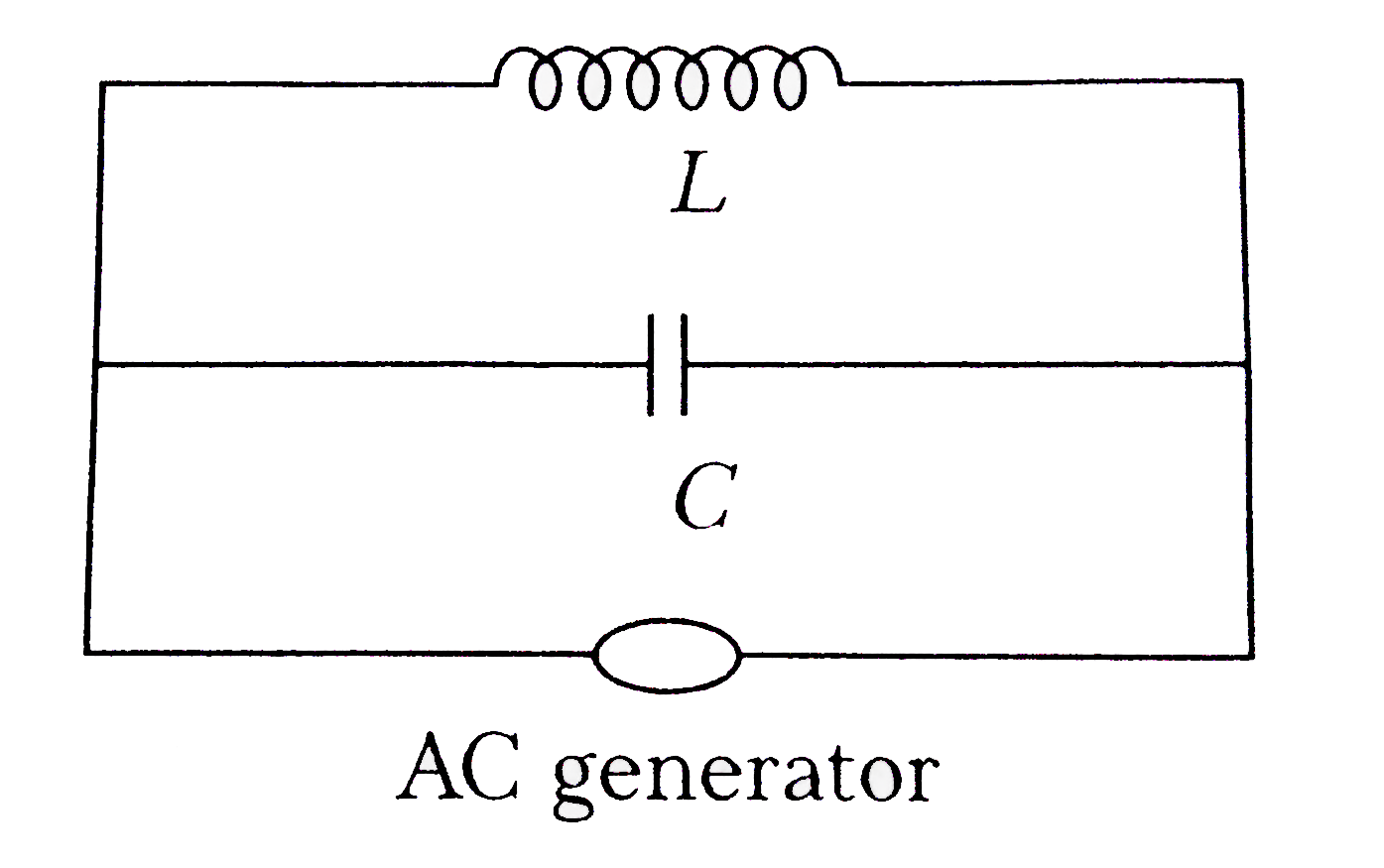
In the circuit shown in the figure , the alternating currents through inductor and capacitor are 1.2 and 1.0 A respectively . The current drawn from the generator is
 A0.4 AB0.2 AC1.0 AD1.2 A
 - Question 2 - Select One
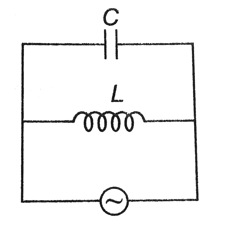
In the AC network shown in figureure the rms current flowing through the inductor and capacitor are 0.6A and 0.8A, respectively. Then the current coming out of the source is
 .A1.0AB1.4AC0.2ADnone of the above
 - Question 3 - Select One
A capacitor and an inductor are connected in parallel across an ac source If the current through the inductor is 0.4 A and that through the capacitor is 0.3 A then the current drawn from the source is .
A0.7AB0.5AC0.1AD√0.07A
Draw phasor diagrams showing phase relationship between voltage and current in an a.c. circuit containing
(a) a pure inductor only, and
(b) a pure capacitor only. Also show graphs of V and I versus time tView SolutionA 200 Mh (pure) inductor, and a 5μF (pure) capacitor , are connected , one by across a singusoidal ac voltage source V=[70.7sin(1000t)] voltage. Obtain the experiessions for the current in each case.
View SolutionCurrent in the circuit is wattless, if
View SolutionAverage power dissipation in a pure capacitor is:
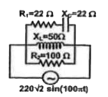
View SolutionThe current through the capacitor in the given circuit is
 View Solution

