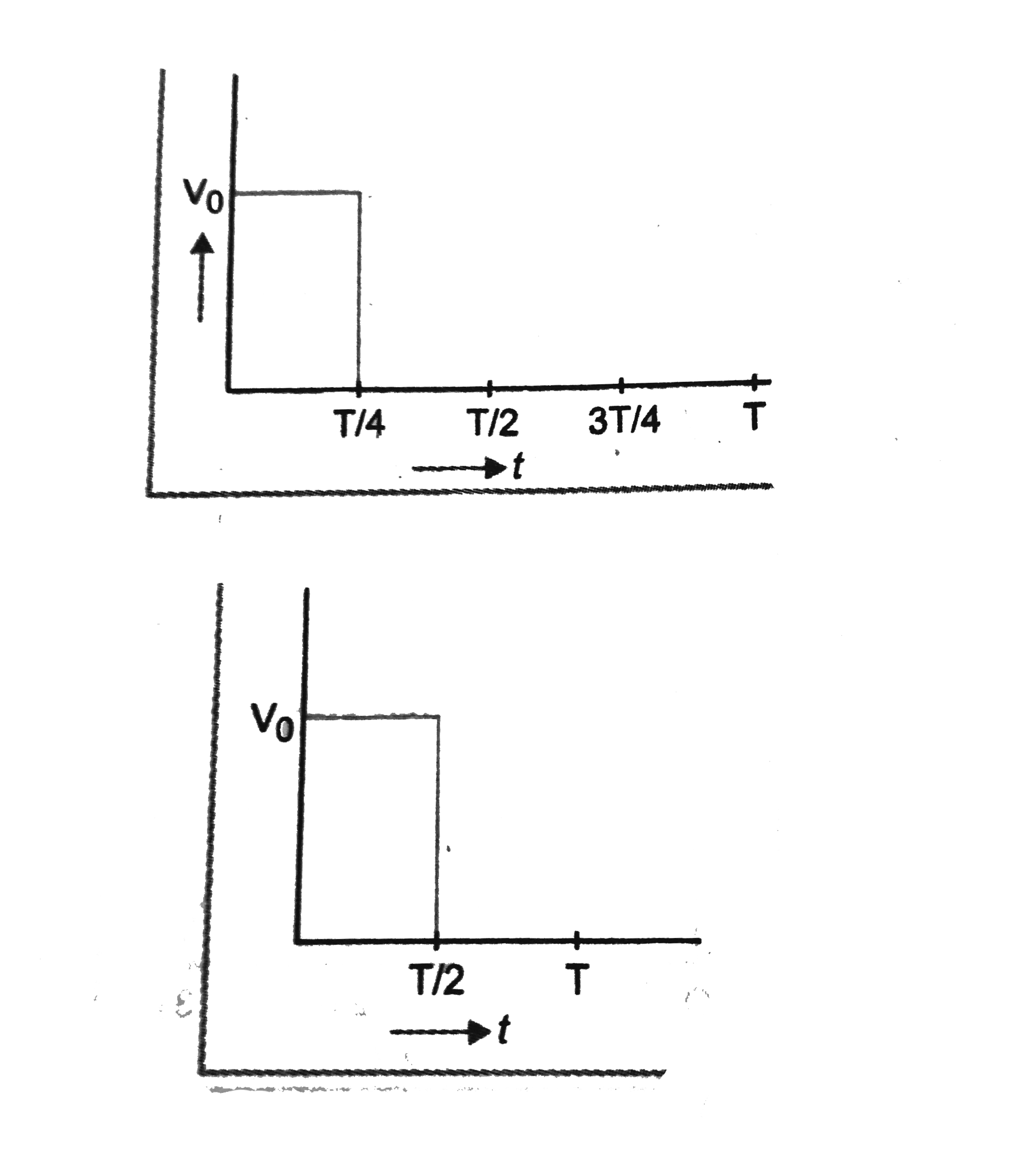
Find rms value of voltage given in Fig.

In Fig. we find, V=V0 form 0 to T/4 and V=0 for the next three quarters of time period.
∴Vrms=√V20+0+004=V02
In Fig. we find V=V0 form 0 to T/2 and V=0 from T/2 to T.
∴Vrms=√V20+02=V0√2
Topper's Solved these Questions
- ELECTROMAGNETIC INDUCTION & ALTERNATING CURRENTBOOK - PRADEEPCHAPTER - ELECTROMAGNETIC INDUCTION & ALTERNATING CURRENTEXERCISE - Solved Examples (b)
1 Videos
- ELECTROMAGNETIC INDUCTION & ALTERNATING CURRENTBOOK - PRADEEPCHAPTER - ELECTROMAGNETIC INDUCTION & ALTERNATING CURRENTEXERCISE - Short Answer Qusetions
2 Videos
- DUAL NATURE OF RADIATION AND MATTERBOOK - PRADEEPCHAPTER - DUAL NATURE OF RADIATION AND MATTEREXERCISE - Exercise
191 Videos
- ELECTROMAGNETIC WAVESBOOK - PRADEEPCHAPTER - ELECTROMAGNETIC WAVESEXERCISE - II Focus multiple choice question
5 Videos
Similar Questions
Knowledge Check
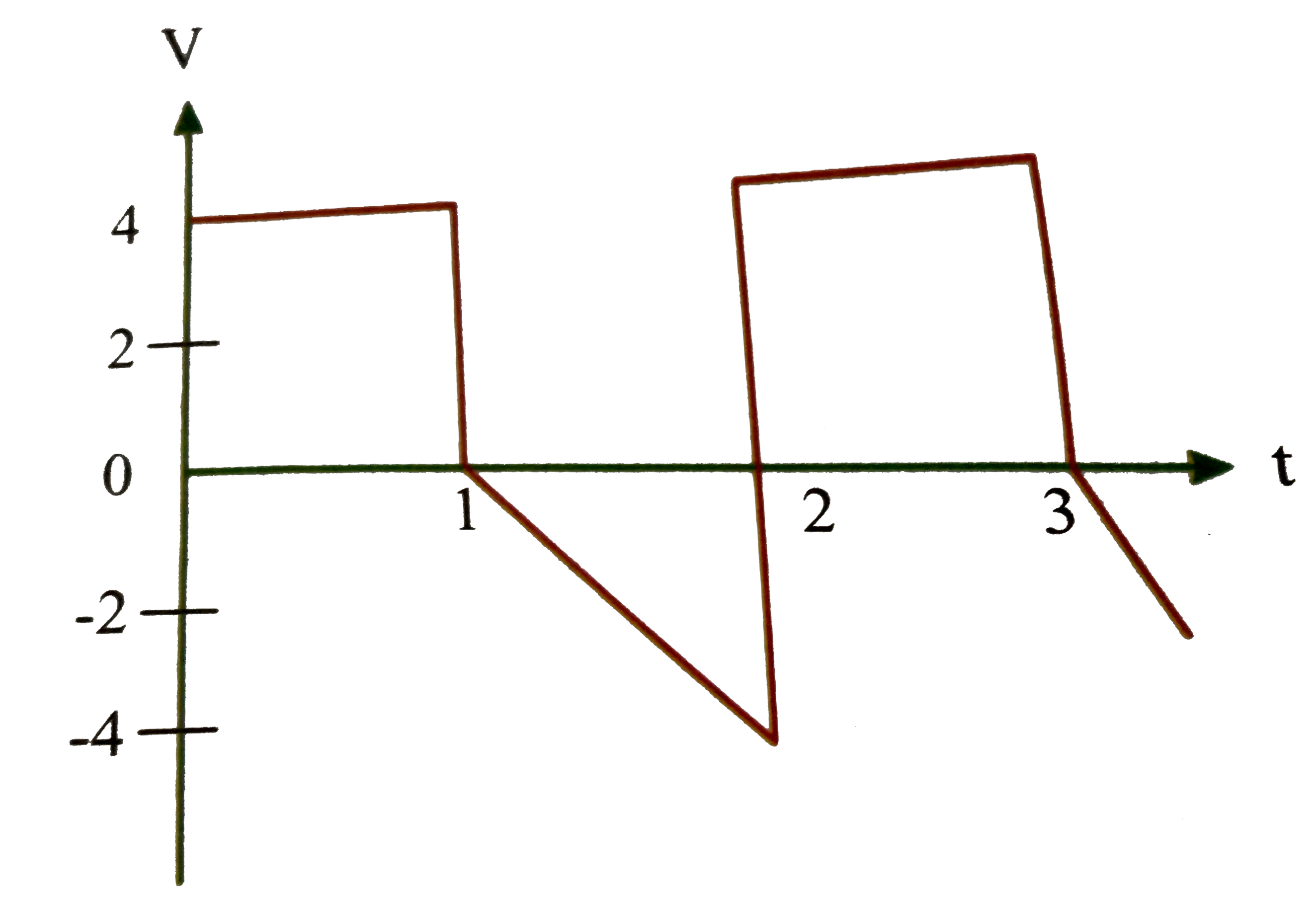
The rms and the average value of the voltage wave shown in figure are
 A√323V,1VB√113V,1VC√113V,3VD√323V,3V
The maximum value of AC voltage in a circuit is 70V. Its r.m.s. value is
A70.7VB100VC500VD707V
A Sinusoidal voltage V = 200 sin 314 t r is applied to a resistor of 10 ohm. Calculate (i) rms value of voltage (ii) rms current (iii) power dissipated as heat.
View SolutionThe rms value of input voltage in a full wave rectifier is 12 V determine the output voltage if a step up a transformer with ratio 1:2 is used
View SolutionIf the voltage in an ac circuit is represented by the equation.
V=220√2sin(314t−ϕ) volt calculate (a) peak and rms value of the voltage, (b) average voltage, (c) frequency of ac.
View SolutionA series combination of circuit elements X and Y is connected across AC mains. The current is ahead of voltage by a phase difference of π /3 radians . The element Y is a resistor of 150 Ω . Name the circuit element X. Calculate the rms value of current if rms value of voltage is 150 V.
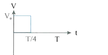
View SolutionA periodic voltage V varies with time t as shown in figure. T is the time period. Find the rms value of the voltage.

View SolutionCalculate the emiter current and collector voltage of the circuit given in Fig. 5.13
View Solution
