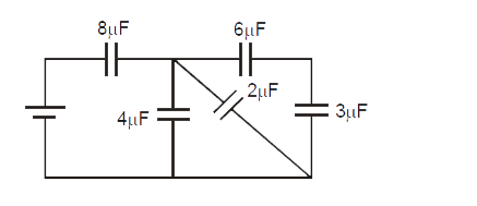
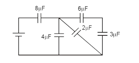
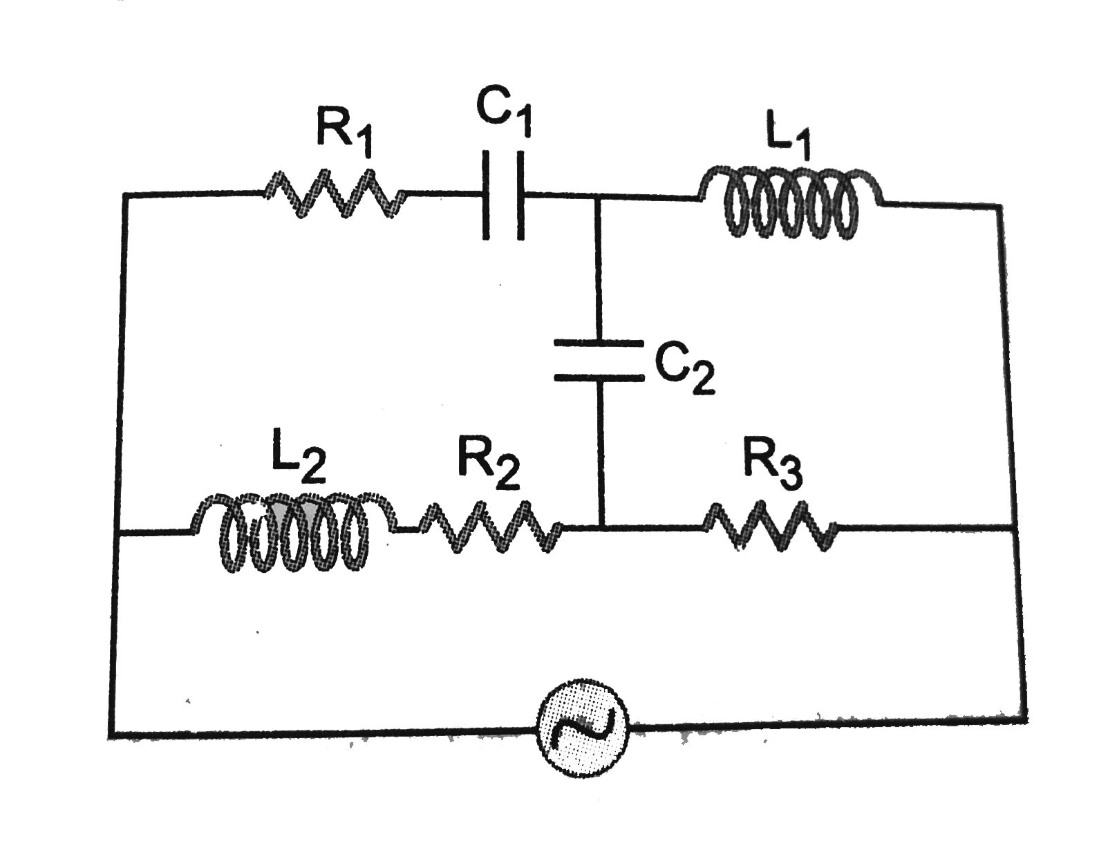
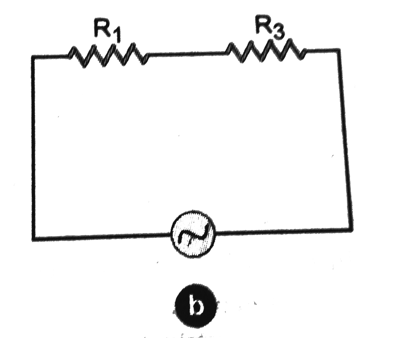
Draw the effective equivalent circuit of the circuit show in Fig. at very high frequencies and find the effective impedance.

Video Solution
Text Solution
At very high frequencies, XC=1ωC=12πvC→ Zero
XL=ωL=2πvL→ extremely high
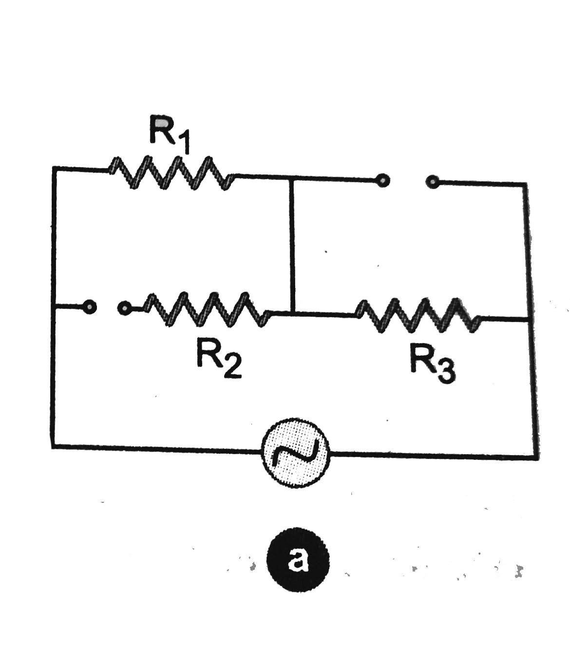
i.e., capacitor is short circuited and inductor blocks the currents (serving as open key). The effective equivalent circuits are show in Fig. (a) and (b).
Effective impedance, Z=R1+R3.
|
Updated on:21/07/2023
Topper's Solved these Questions
- BOOK - PRADEEPCHAPTER - ELECTROMAGNETIC INDUCTION & ALTERNATING CURRENTEXERCISE - Solved Examples (b)1videos
ELECTROMAGNETIC INDUCTION & ALTERNATING CURRENT
- BOOK - PRADEEPCHAPTER - ELECTROMAGNETIC INDUCTION & ALTERNATING CURRENTEXERCISE - Short Answer Qusetions2videos
ELECTROMAGNETIC INDUCTION & ALTERNATING CURRENT
- BOOK - PRADEEPCHAPTER - DUAL NATURE OF RADIATION AND MATTEREXERCISE - Exercise191videos
DUAL NATURE OF RADIATION AND MATTER
- BOOK - PRADEEPCHAPTER - ELECTROMAGNETIC WAVESEXERCISE - II Focus multiple choice question5videos
ELECTROMAGNETIC WAVES
Similar Questions
Knowledge Check
- Question 1 - Select One
The natural frequency of the circuit shows in Fig. is
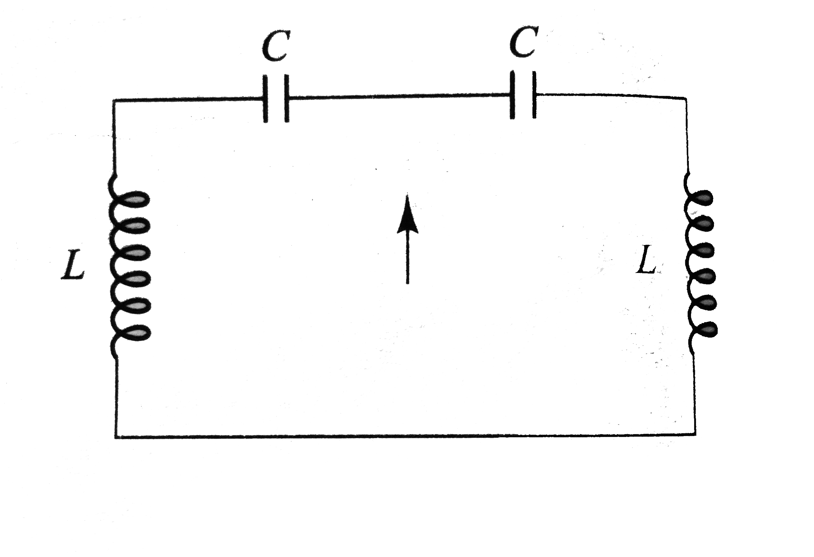 A1√LCB1√2LCC2√LCDNone of these
 - Question 2 - Select One
In the circuit shown in fig, the resonant frequency is
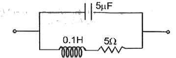 A75kcsB750kcsC7.5kcsD75mcs
 - Question 3 - Select One
Resultant impedence of the circuit is
A3.5ωB4.0ΩC4.5ΩD5.0Ω
Find the equivalent resistnace of the circuit shown in fig between the points A and B
 View Solution
Find the effective resistance of the following circuit :
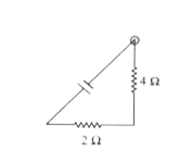 View Solution
What is the effective resistance in the given circuit?
View Solution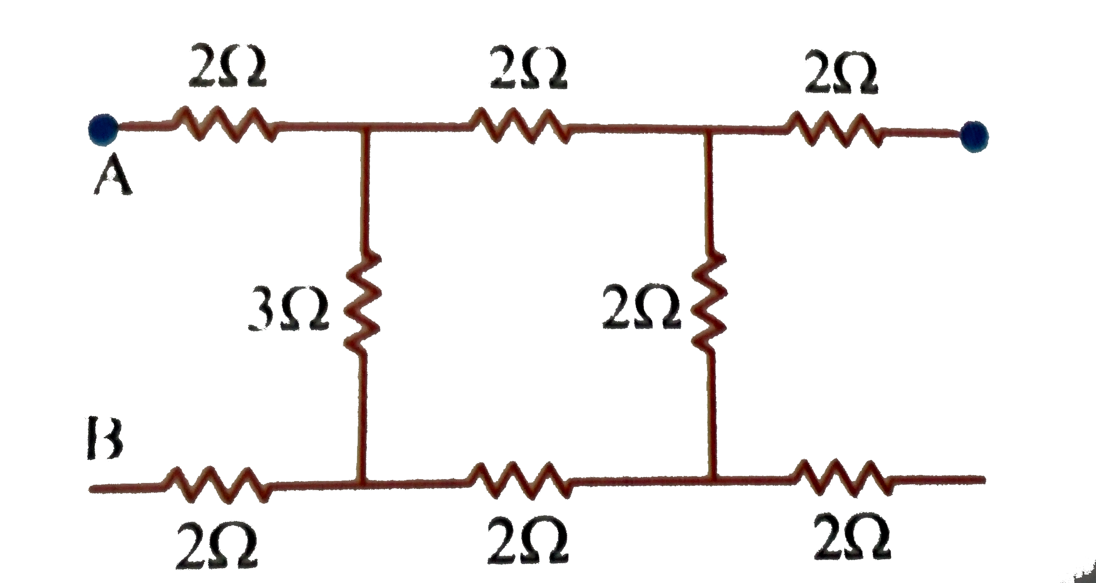
The effective between A&B in the given circuit isView SolutionIn the circuit shows in Fig the switch is closed at t=0.
 View Solution


