Study the circuit (a) and (b) shown in Fig. and answer the following questions.
(a) Under which conditions would the rms currents in the two circuits be the same ?
Can the rms curent in circuit (b) be larger than that in (a) ?
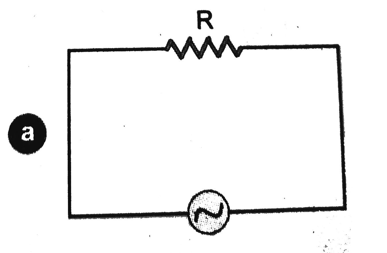
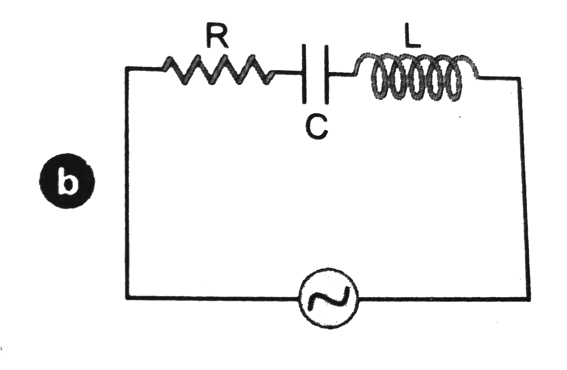
In fig. (a), Iv=EvR
In fig. (b), I'v=EvZ=Ev√R2+(XL−XC)2
Clearly, I'υ=Iυ only when XL=XC, i.e., at resonance only.
(b) As R≤Z, so Ia≥Ib
Therefore, rms current in cuicuit (b) cannot be larger than that in circuit (a).
Topper's Solved these Questions
- BOOK - PRADEEPCHAPTER - ELECTROMAGNETIC INDUCTION & ALTERNATING CURRENTEXERCISE - Solved Examples (b)1videos
ELECTROMAGNETIC INDUCTION & ALTERNATING CURRENT
- BOOK - PRADEEPCHAPTER - ELECTROMAGNETIC INDUCTION & ALTERNATING CURRENTEXERCISE - Short Answer Qusetions2videos
ELECTROMAGNETIC INDUCTION & ALTERNATING CURRENT
- BOOK - PRADEEPCHAPTER - DUAL NATURE OF RADIATION AND MATTEREXERCISE - Exercise191videos
DUAL NATURE OF RADIATION AND MATTER
- BOOK - PRADEEPCHAPTER - ELECTROMAGNETIC WAVESEXERCISE - II Focus multiple choice question5videos
ELECTROMAGNETIC WAVES
Similar Questions
Study the circuit (a) and (b) shown in Fig. and answer the following questions.
(a) Under which conditions would the rms currents in the two circuits be the same ?
Can the rms curent in circuit (b) be larger than that in (a) ?

 View Solution
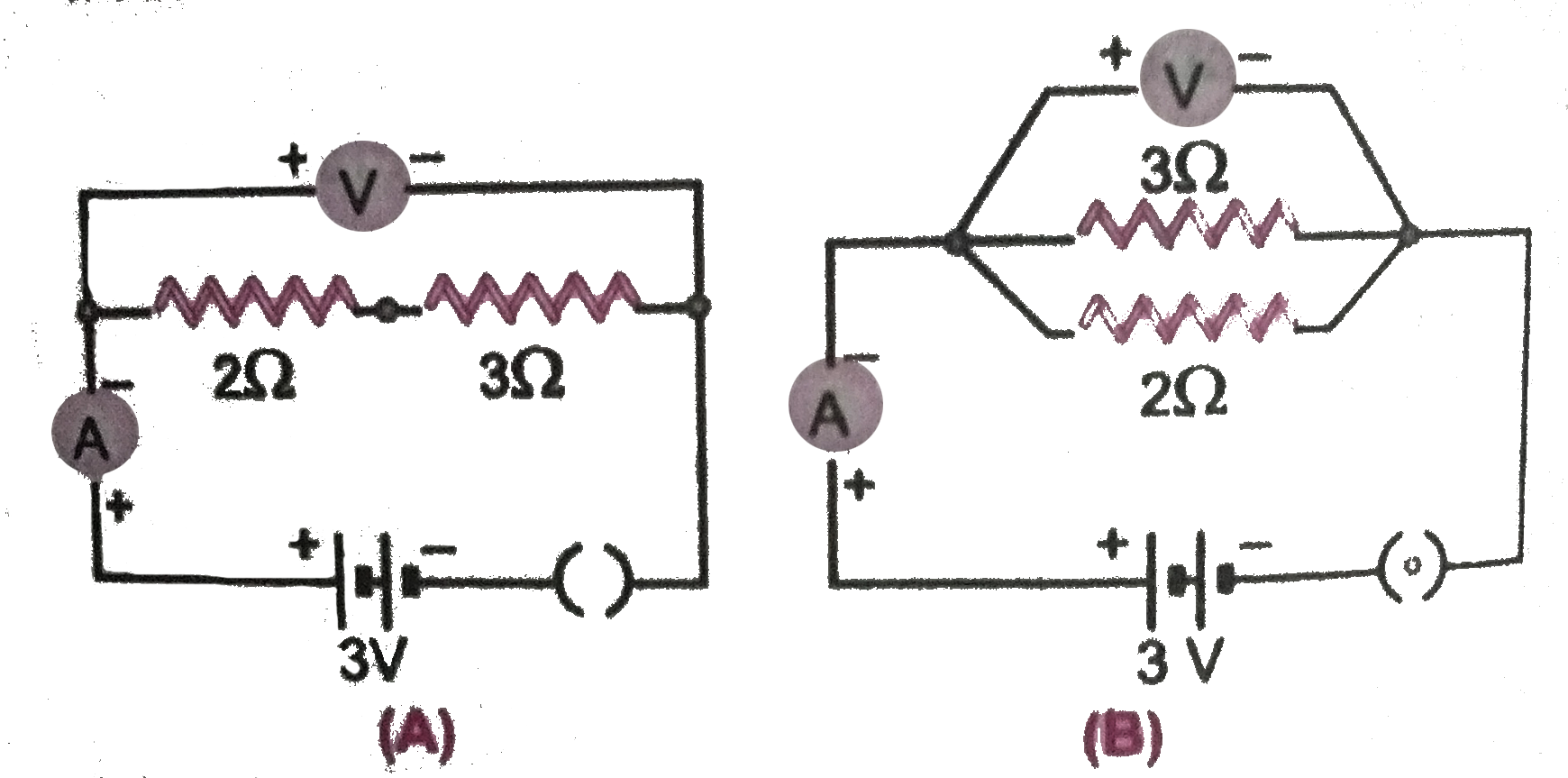
For the circuits AandB shown in (Fig. 3.64), what would be the voltmeter readings ?
 .View Solution
Knowledge Check
- Question 1 - Select One or More
For the circuit shown in Fig. Which of the following statements are correct?
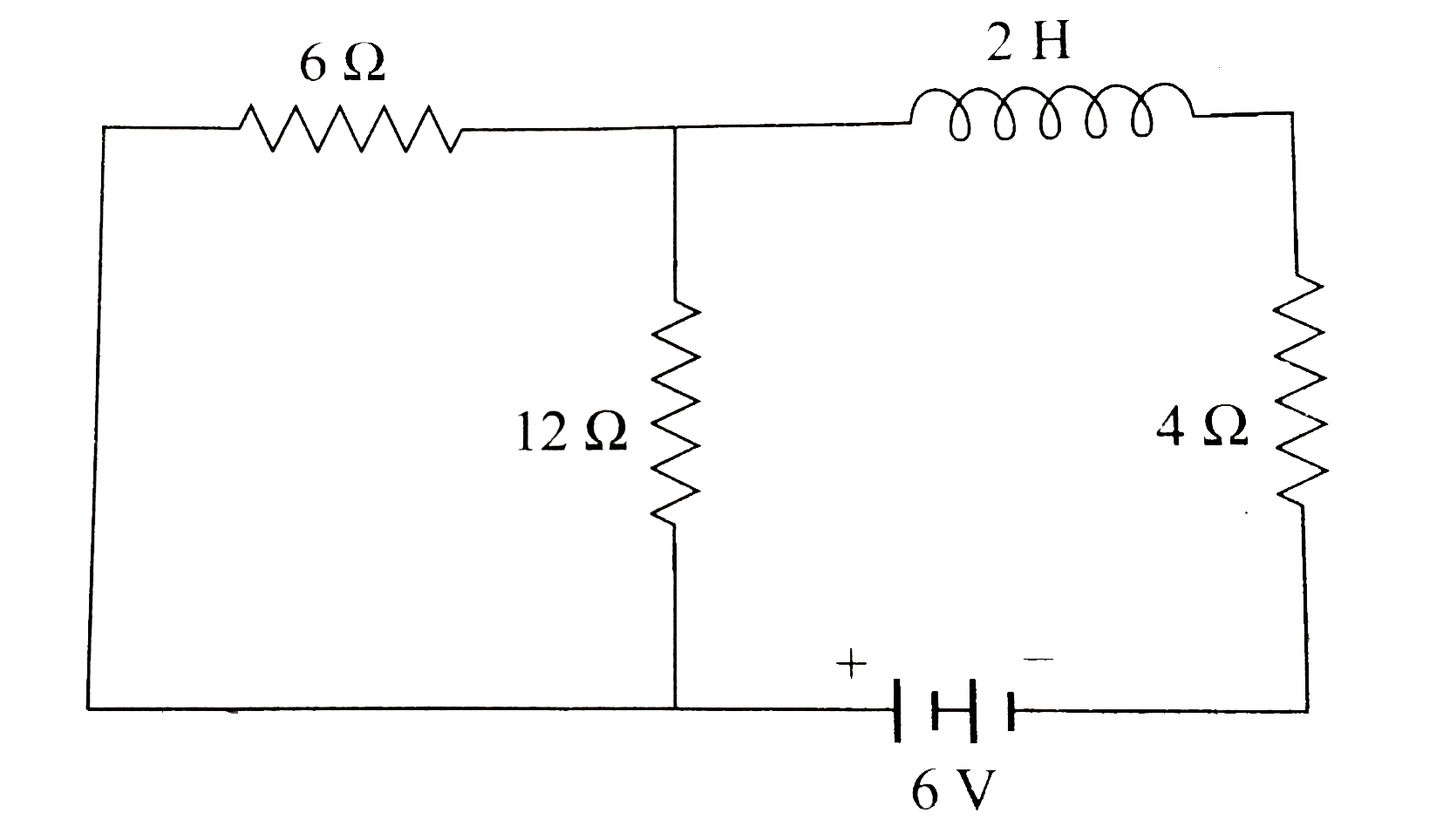 AIts time constant is 0.25 sBIn steady sate, current through inductance will be equal to zeroCIn steady state, current through the battery will be equal to 0.75 ADNone ot the above.
 - Question 2 - Select One
See the electrical circuit shown in Fig. Which of the following equations is a correct equation for it ?
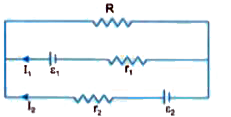 Aε1−(i1+i2)R−i1r1=0Bε2−i2r2−ε1−i1r1=0C−ε2−(i1+i2)R+i2r2=0Dε1−(i1+i2)R+i1r1=0
 - Question 3 - Select One
For the circuit shown figure answer the following questions
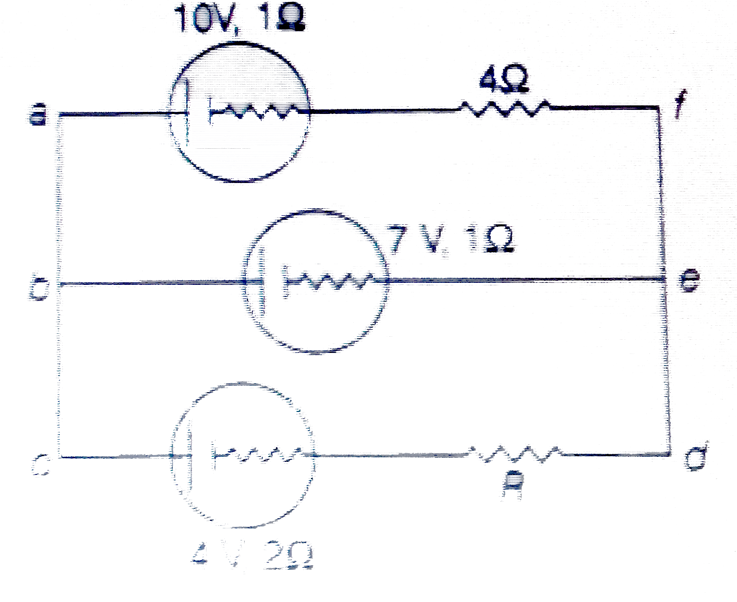
For what value of R, current through 7V battery is zero?A3ΩB4ΩC5ΩD6Ω
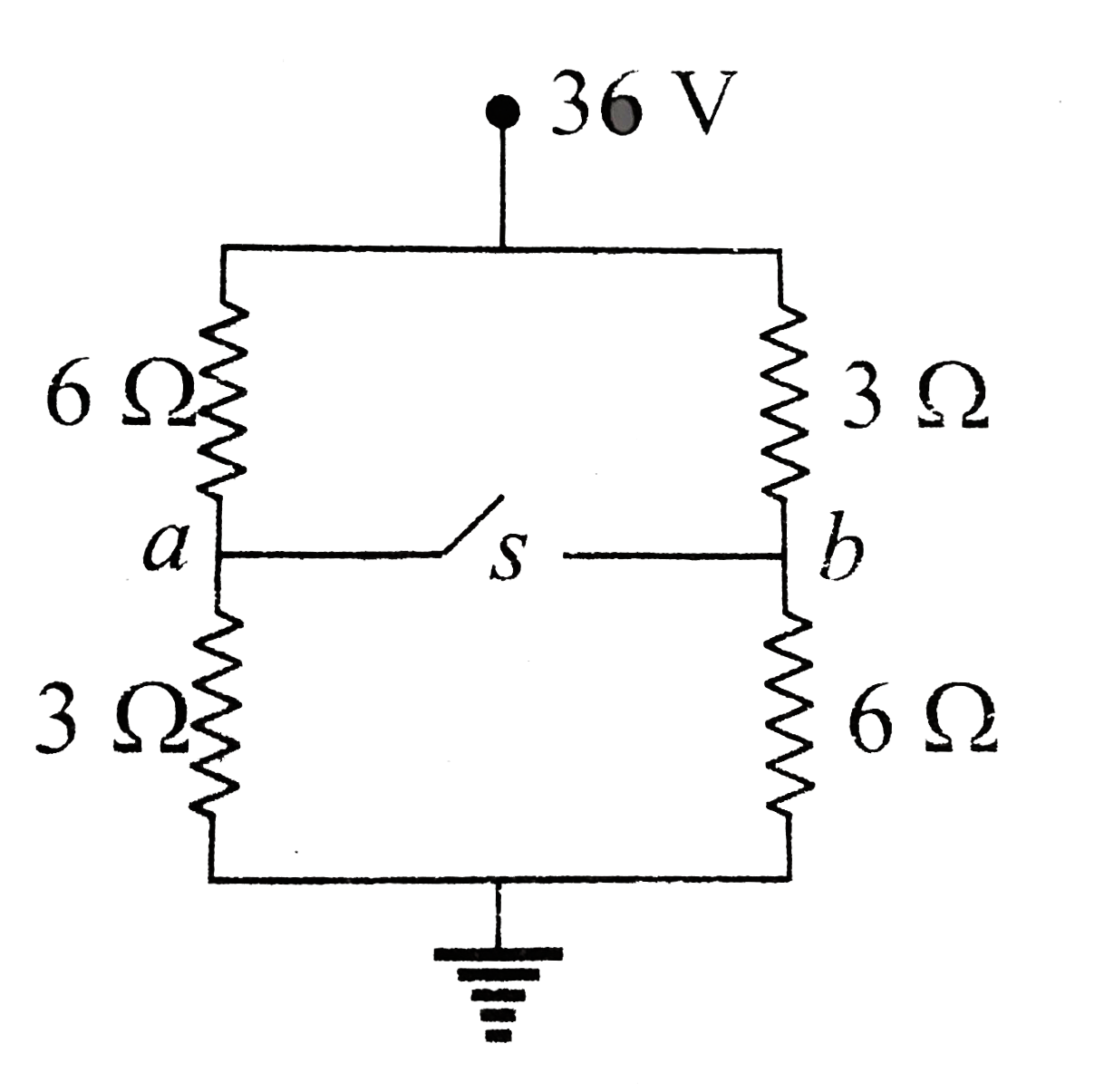
In the circuit shown in fig. calculate the following:
a. Potential differece between points a and b when switch S is open.
b.Current through S in the circuit
 View Solution
Find current i in the circuit in the following cases.
(a)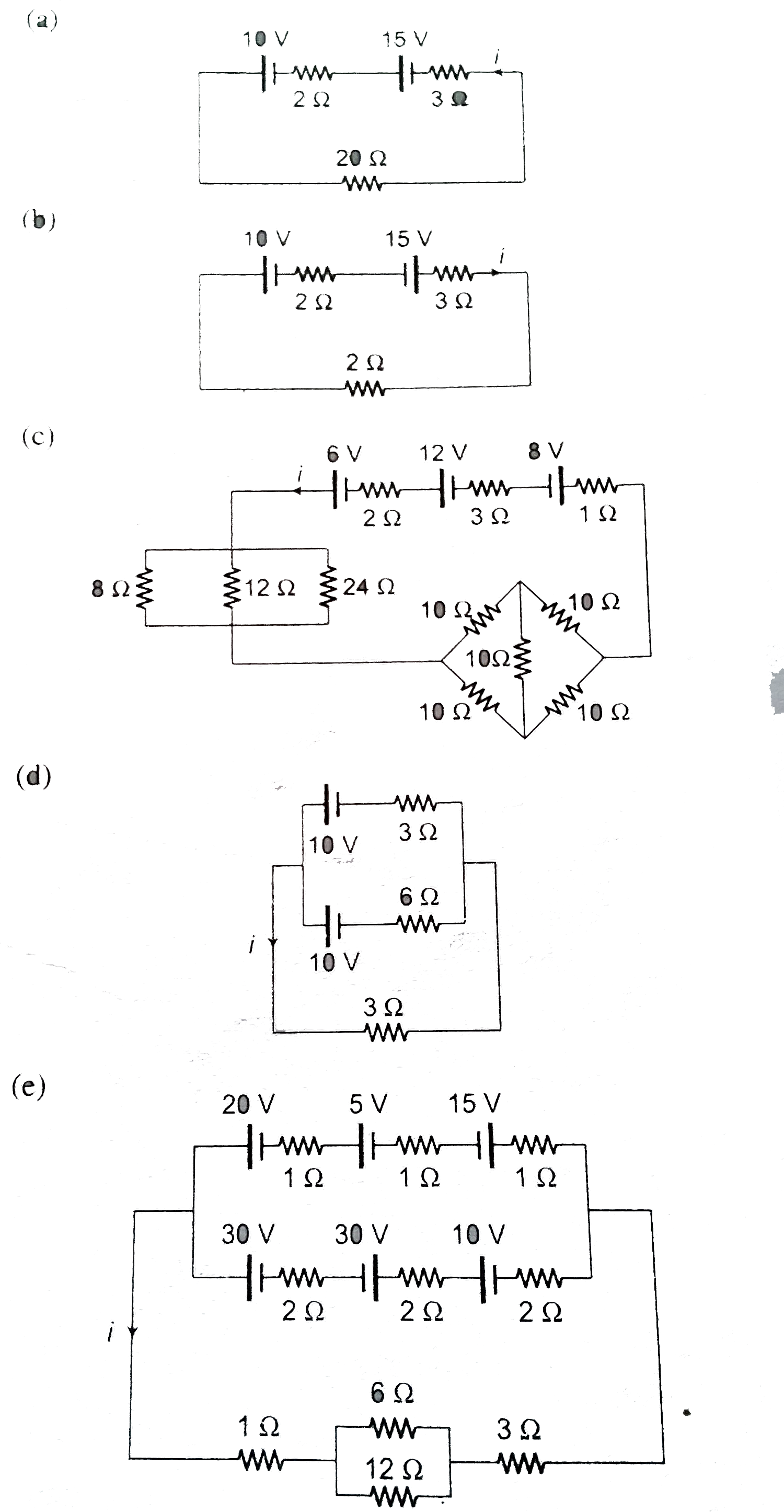
(b)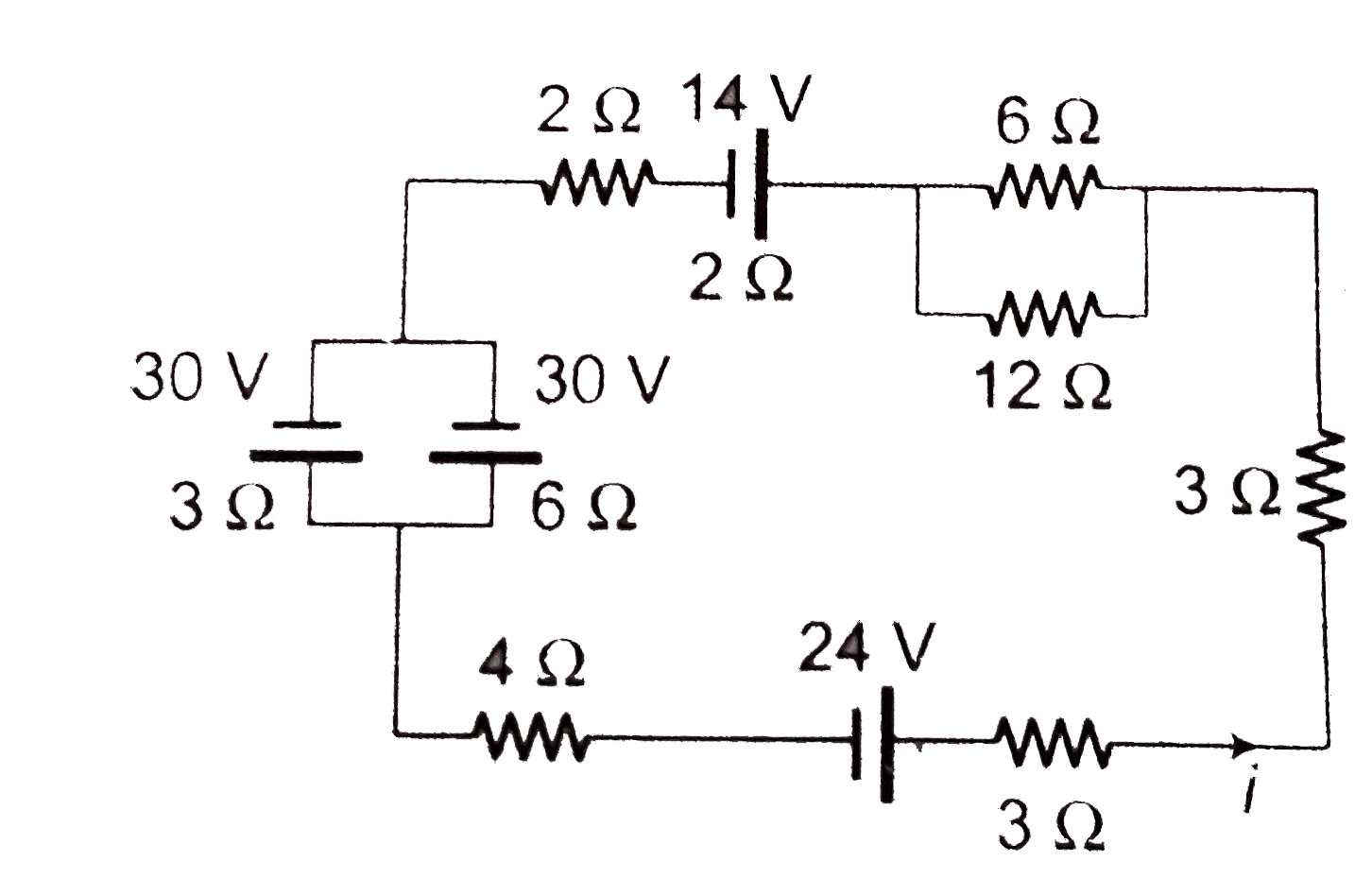 View Solution
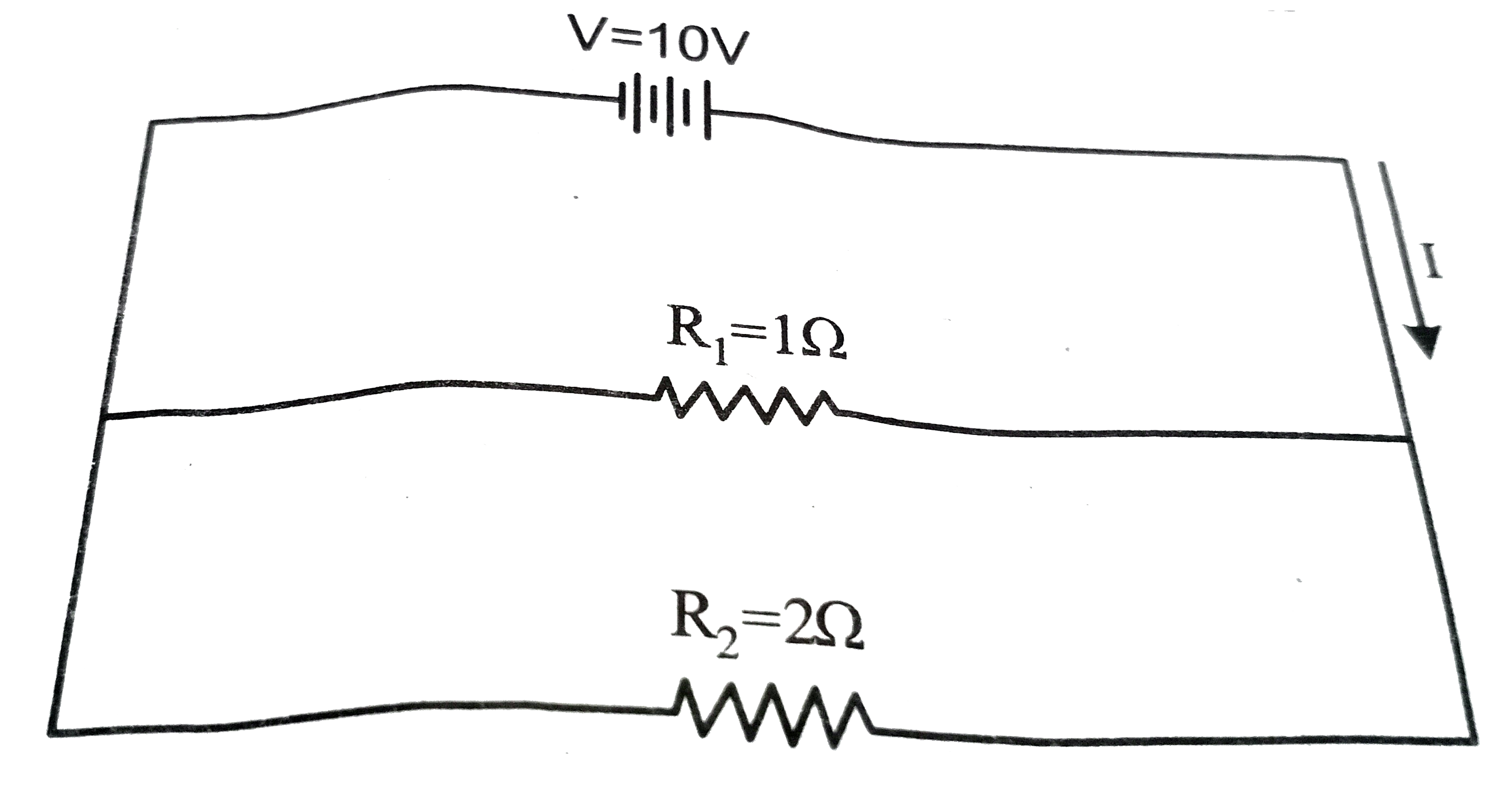
Which one of the following is the value of current I in the circuit shown above?View SolutionWhich one of the following equation is correct for the circuit shown. The currents in each branch of circuit are indicated and all three cells are ideal
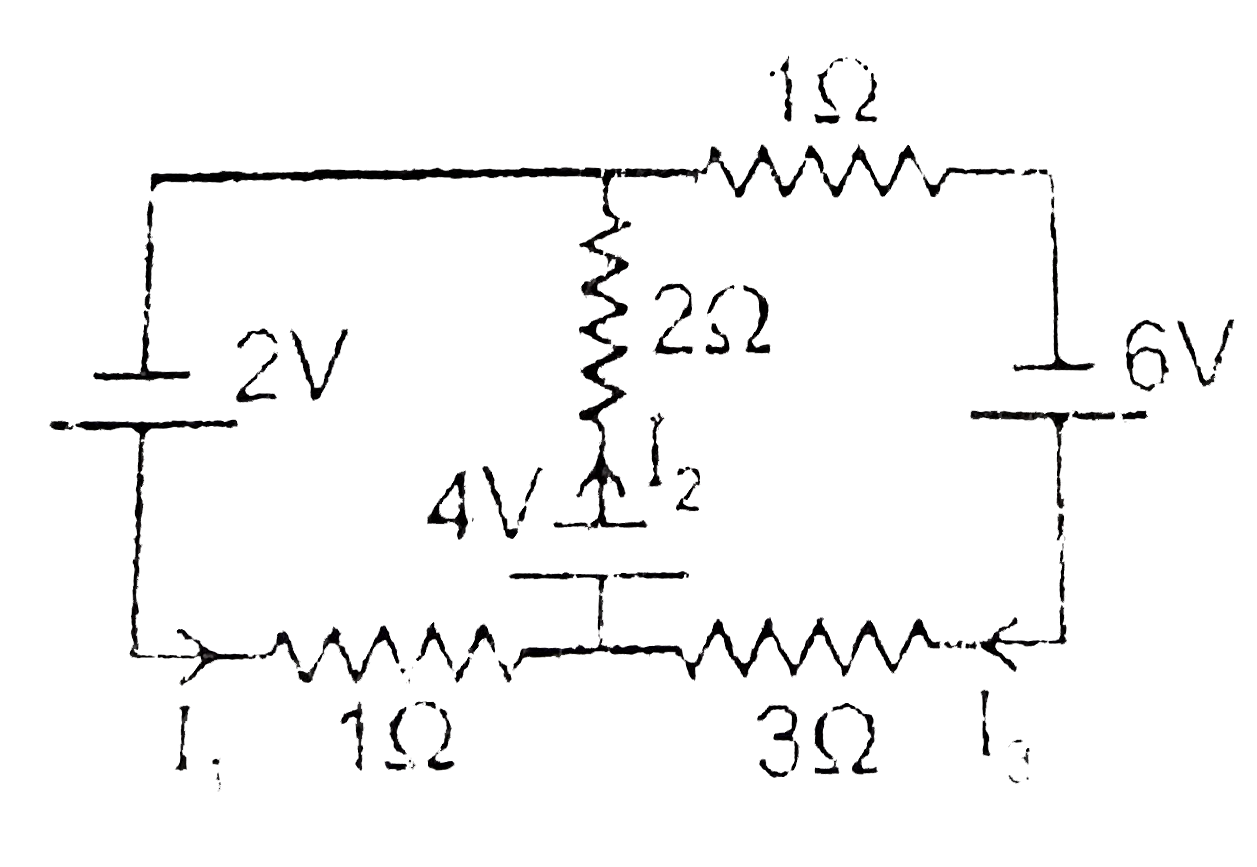 View Solution
Which one of the following equation is correct for the circuit shown. The currents in each brach of circuit are indicated and all three cells are ideal.
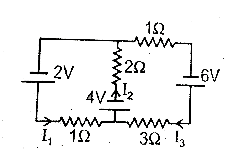 View Solution

