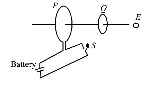
As shown in the figure, P and Q are two coaxial conducting loops separated by some distance. When the switch S is closed, a clockwise current (as seen by E) and an induced current flows in Q. The switch remains closed for a long time. when S is opened, a current flows in Q. Then the direction (as seen by E) are
A
respectively clockwise and anticlockwise
B
both clockwise
C
both anticlockwise
D
respectively anticlockwise and clockwise
Video Solution
Text Solution
The correct Answer is:D
When switch S is closed, Fig. current in coil P increases in clockwise direction. Induced currrent in Q must opposei this increase, as per Len'z law. Therefore, induced current in Q i.e., must be anticlockwise.
When switch S is opened current in coil P decreases. Induced current in Q oppoes this decrease. as per Lenz's law. Therefore,induced current in Q, i.e., must be clockwise.
|
Topper's Solved these Questions
- ELECTROMAGNETIC INDUCTION & ALTERNATING CURRENTBOOK - PRADEEPCHAPTER - ELECTROMAGNETIC INDUCTION & ALTERNATING CURRENTEXERCISE - JEE Mains Ad..(Multiple Choice Question)
1 Videos
- ELECTROMAGNETIC INDUCTION & ALTERNATING CURRENTBOOK - PRADEEPCHAPTER - ELECTROMAGNETIC INDUCTION & ALTERNATING CURRENTEXERCISE - Multiple Choice Questions
1 Videos
- ELECTROMAGNETIC INDUCTION & ALTERNATING CURRENTBOOK - PRADEEPCHAPTER - ELECTROMAGNETIC INDUCTION & ALTERNATING CURRENTEXERCISE - Value Based Questions
2 Videos
- DUAL NATURE OF RADIATION AND MATTERBOOK - PRADEEPCHAPTER - DUAL NATURE OF RADIATION AND MATTEREXERCISE - Exercise
191 Videos
- ELECTROMAGNETIC WAVESBOOK - PRADEEPCHAPTER - ELECTROMAGNETIC WAVESEXERCISE - II Focus multiple choice question
5 Videos
Similar Questions
Knowledge Check
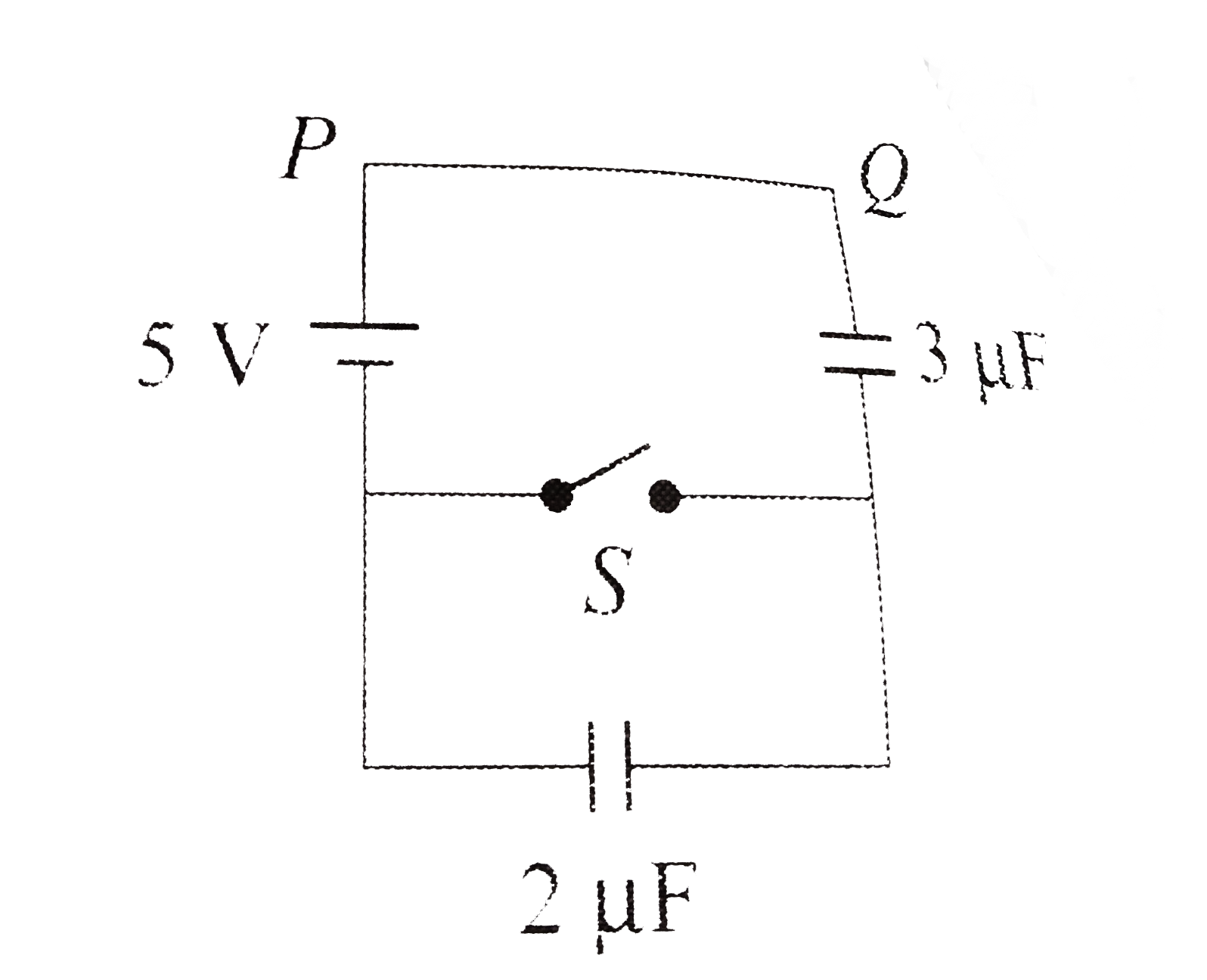
In fig. A2.27, the charge that flows from P to Q when the switch S is closed is
 A3μCB6μCC9μCD15μC
In the circuit shown, the switch is closed at t=0, the currents I1,I2 and I3 are
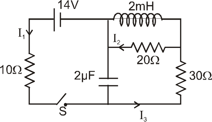 A1.4A,0,0B1.4 A,0.70 A,0.70 AC0,0,0D1.2A,0.6A,0.6A
In the circuit shown in the figure The steady state currents i1andi2 in the coils after the switch S is closed are
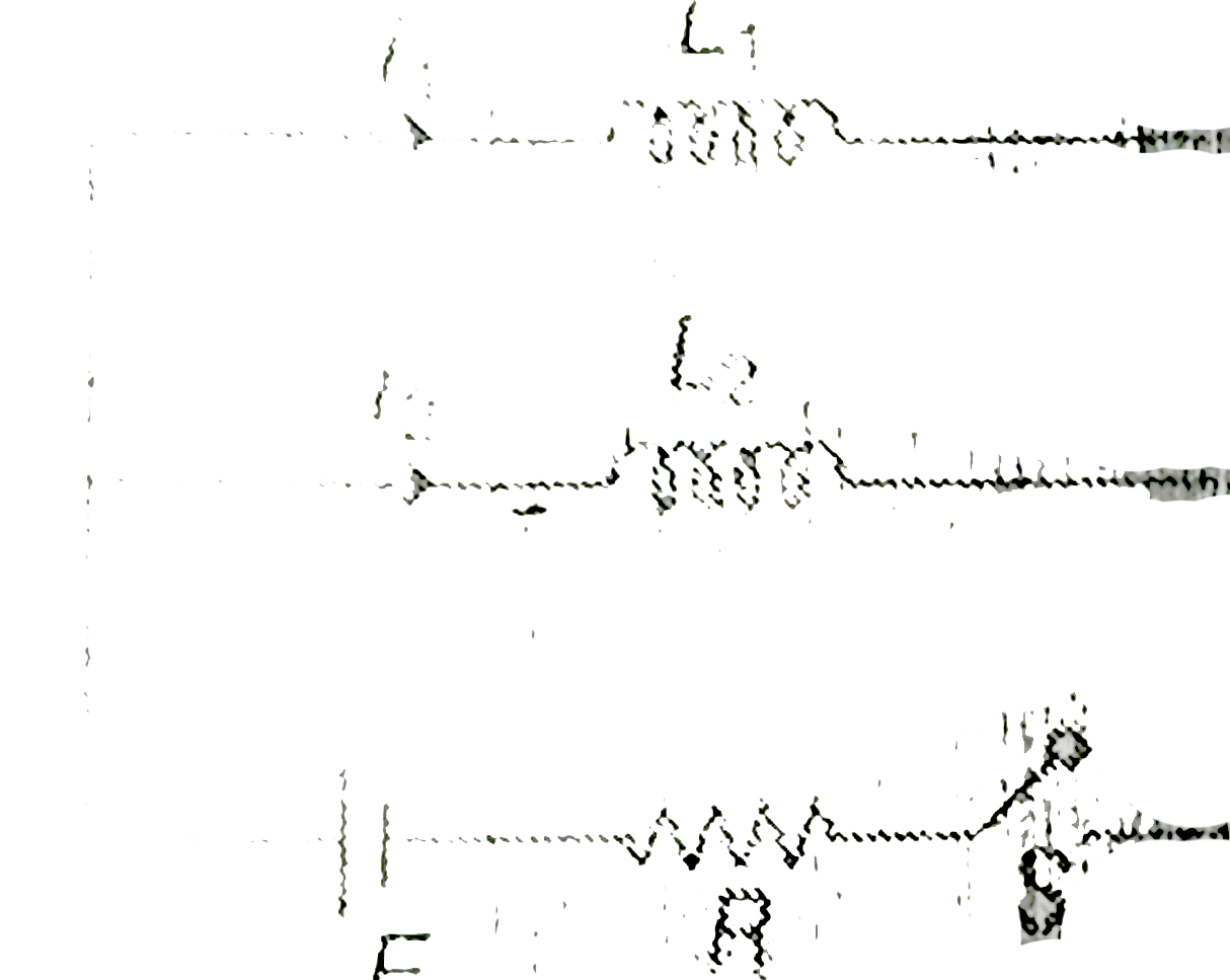 Ai1=EL2R(L1+L2)Bi1=EL1R(L1+L2)Ci2=EL2R(L1+L2)Di2=E√L1L2RL2
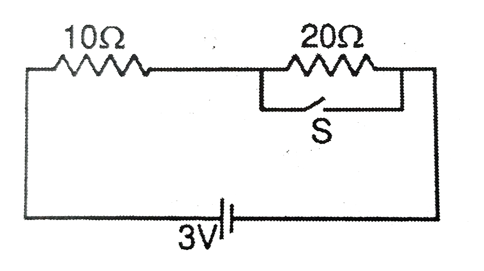
Consider the circuit shown in figure. Find the current through the 10Ω resistor when the switch S is (a) opened (b) closed.
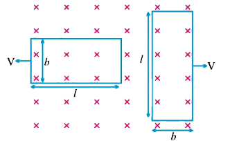
View SolutionIn the figure shown, coils P and Q are identical and moving apart with same velocity V. Induced currents in the coils are I1andI2. Find I1/I2.
View SolutionIn the circuit shown in figure switch S is closed at time t=0
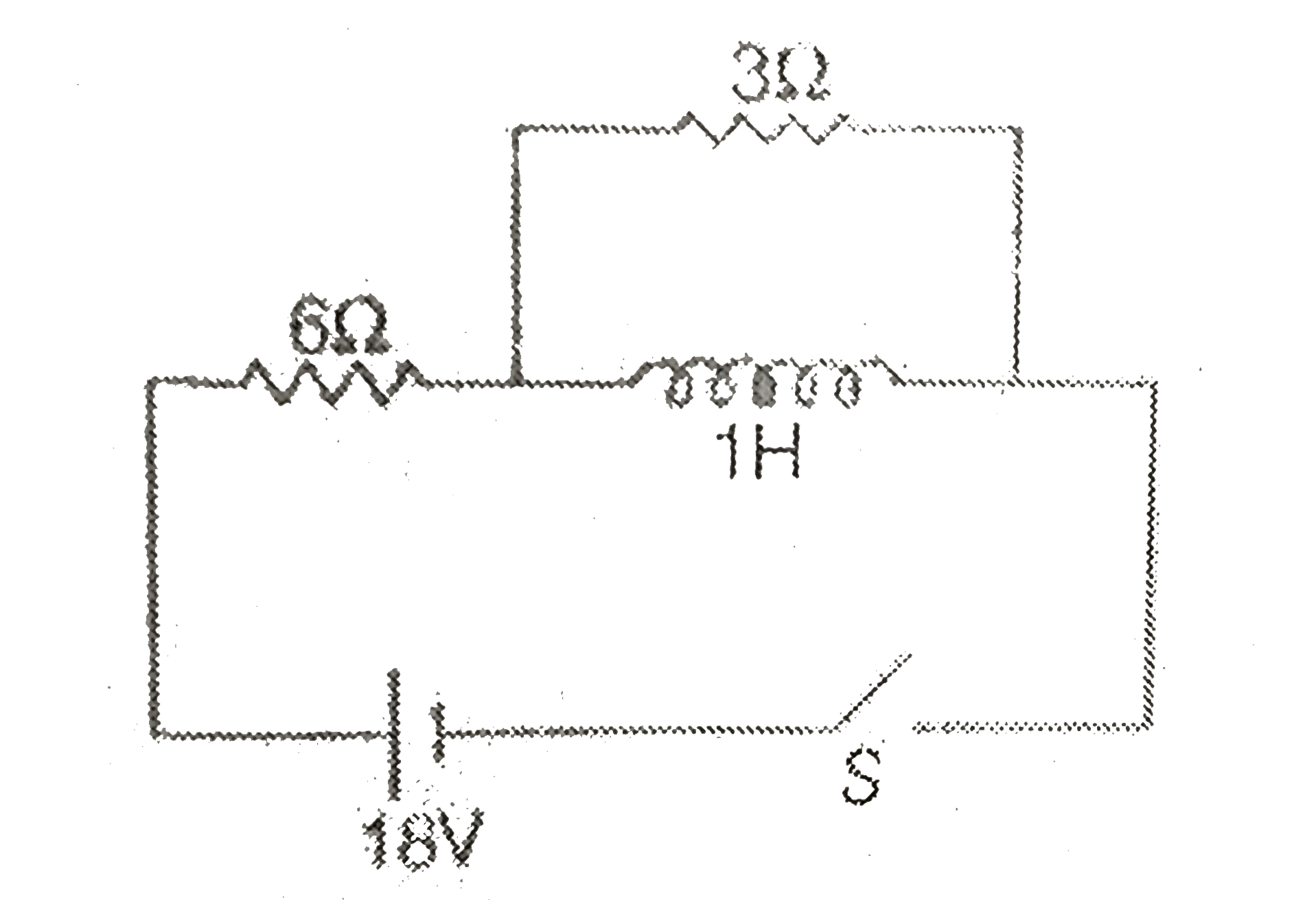
Current I from the battery at time t is given by
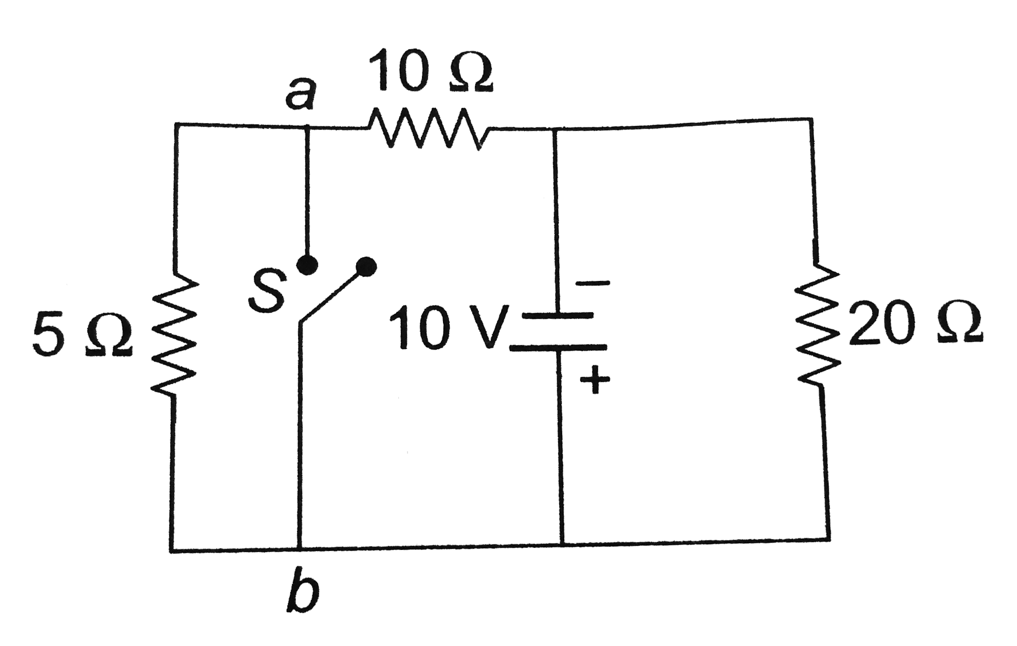
View SolutionIn the circuit shown below, the current that flows from a to b when switch S is closed is
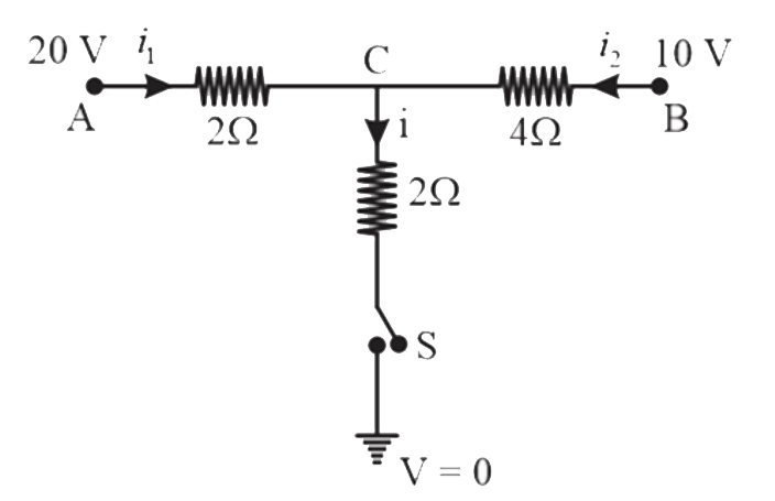
View SolutionWhen the switch S, in the circuit shown , is closed , then the Value of current i will be :
View Solution

