Consider the half wave rectifier circuit Fig.Assume the diode to be a silicon diode with a thershold voltage of 0.7V. Draw the output if the input is a sine wave with an amplitude of 2V.
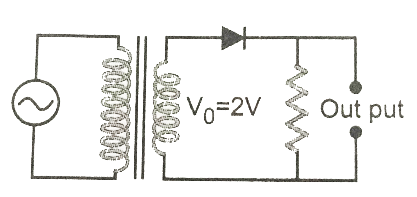
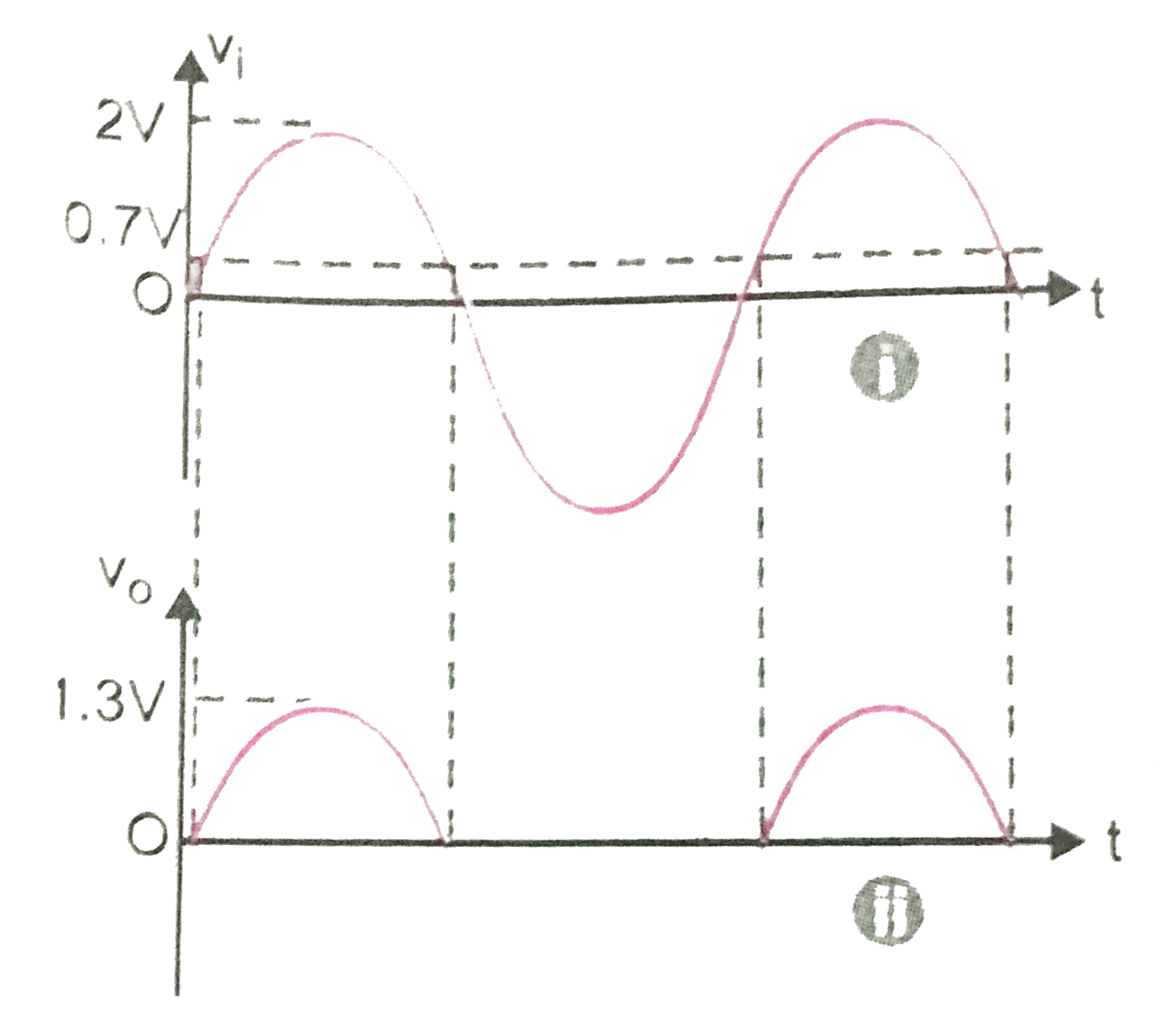
Since the diode threshold voltage is 0.7V, the diode will not conduct till the input voltage reaches from 0 to 0.7V. It will conduct from 0.7V to 2V input voltage and again till the input voltage falls down to 0.7V. Thus, the input and output wave from for the half wave rectifier will be as shown in the Fig. (i) and (ii) respectively.
Topper's Solved these Questions
- BOOK - PRADEEPCHAPTER - ELECTRONIC DEVICESEXERCISE - SAMPLE PROBLEM2videos
ELECTRONIC DEVICES
- BOOK - PRADEEPCHAPTER - ELECTRONIC DEVICESEXERCISE - CONCEPTUAL PROBLEMS1videos
ELECTRONIC DEVICES
- BOOK - PRADEEPCHAPTER - ELECTROMAGNETIC WAVESEXERCISE - II Focus multiple choice question5videos
ELECTROMAGNETIC WAVES
- BOOK - PRADEEPCHAPTER - ELECTROSTATICSEXERCISE - ASSERTION-REASON TYPE QUESTIONS2videos
ELECTROSTATICS
Similar Questions
Consider a silicon diode with a threshold voltage of −0.7V, used as a half wave rectifier. Draw the output if the input is a sine wave from of amplitude 2V and circuit is on in reverse position.
View SolutionIn the half-wave rectifier circuit shown, which one of the following waveform is true for VCD the output across C and D?
 View Solution
Knowledge Check
- Question 1 - Select One
A full wave rectifier circuit along with the input and output are shown in Fig. the concentrations from the diode I is (are)
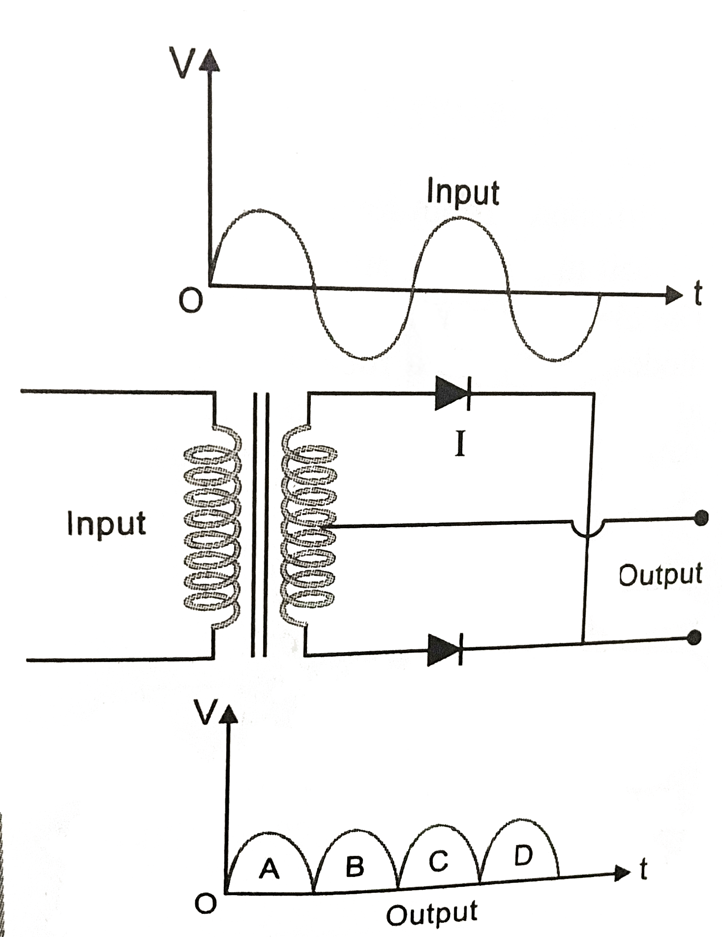 ACBA, CCB, DDA, B, C, D
 - Question 2 - Select One
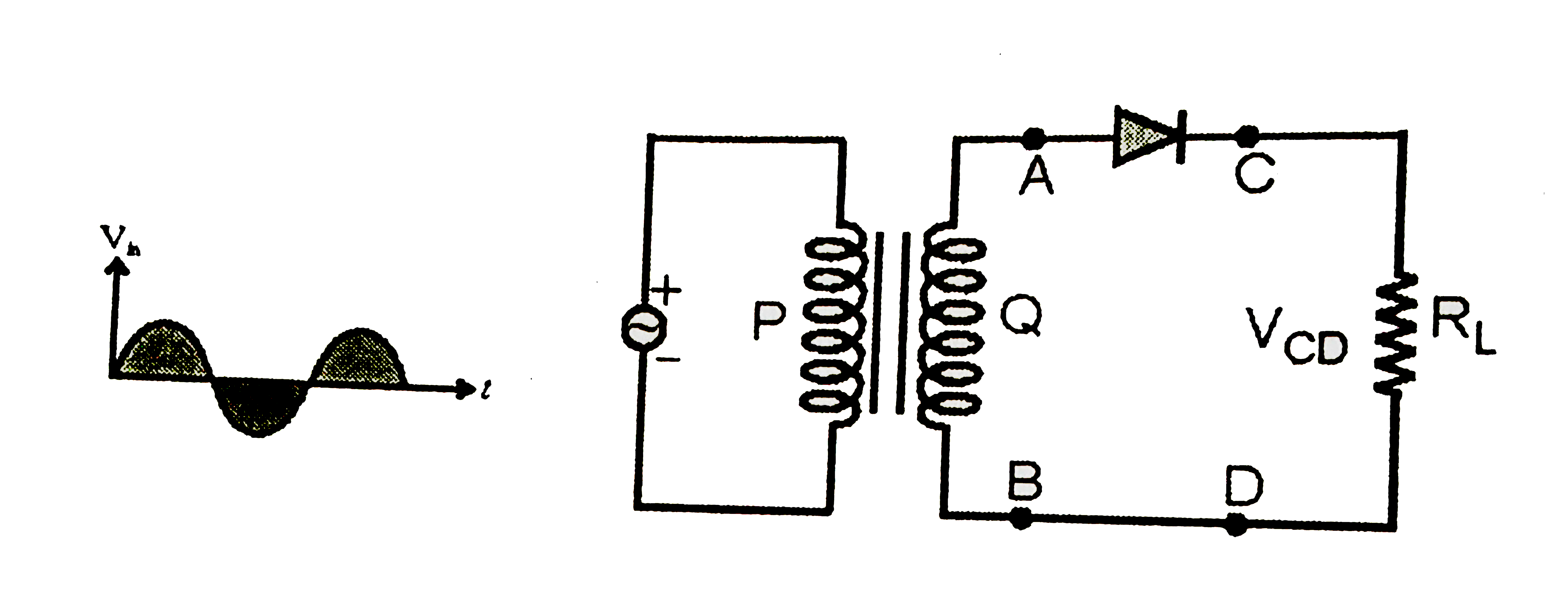
In the half-wave rectifier circuit shown. Which one of the following wave forms in true for VCD, if the input is as shown?A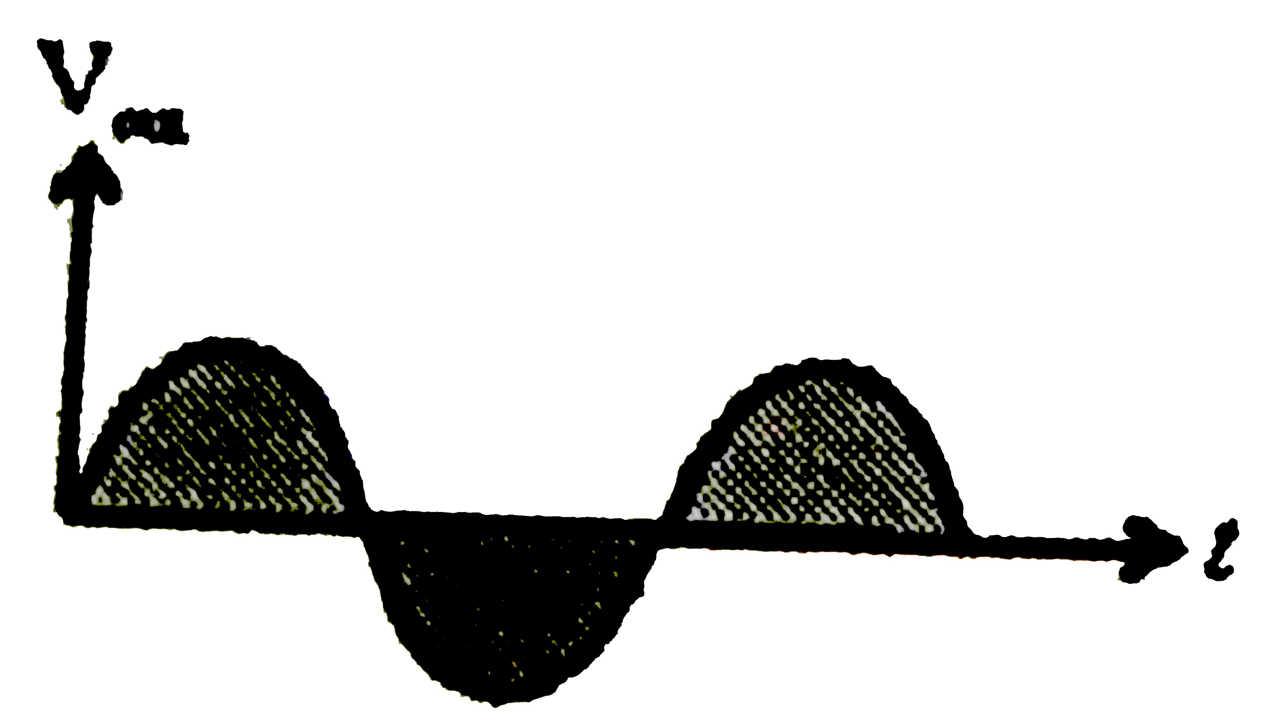 B
B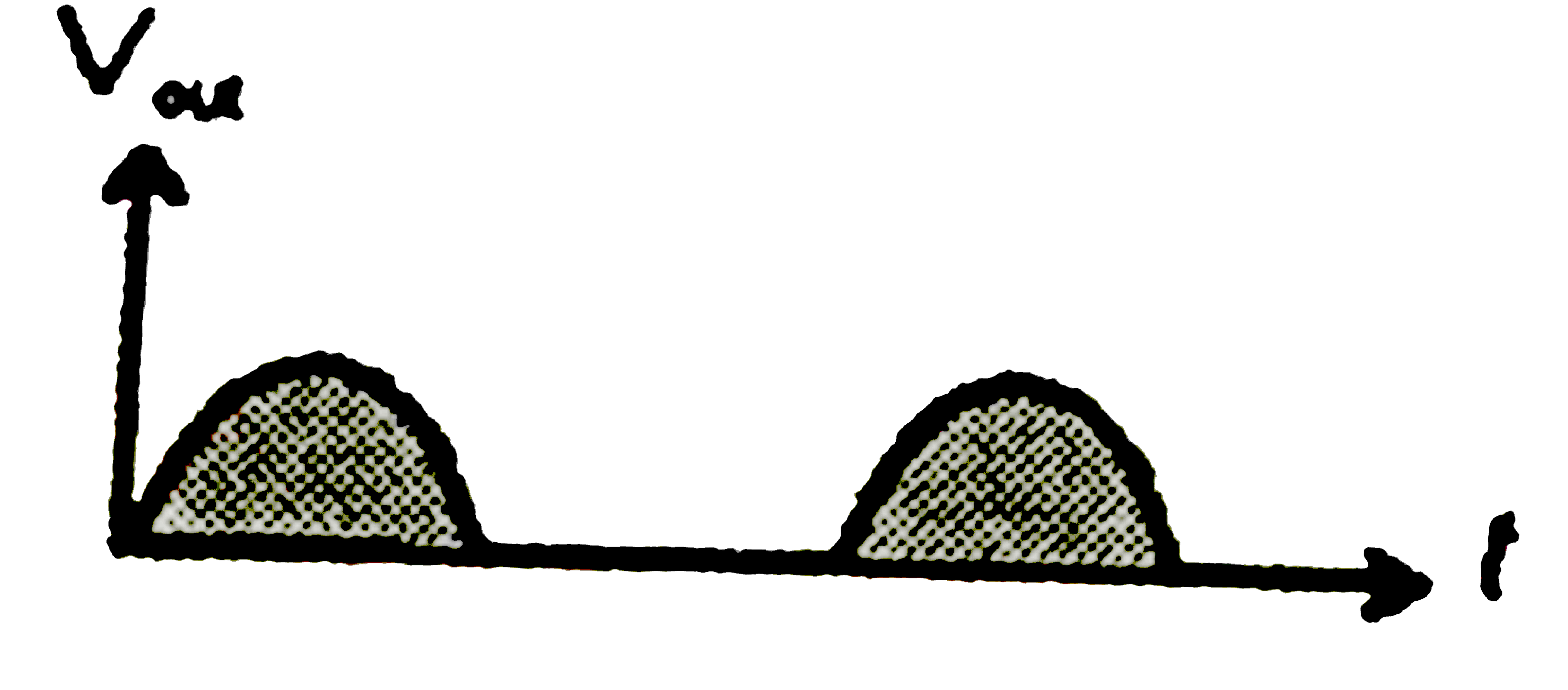 C
C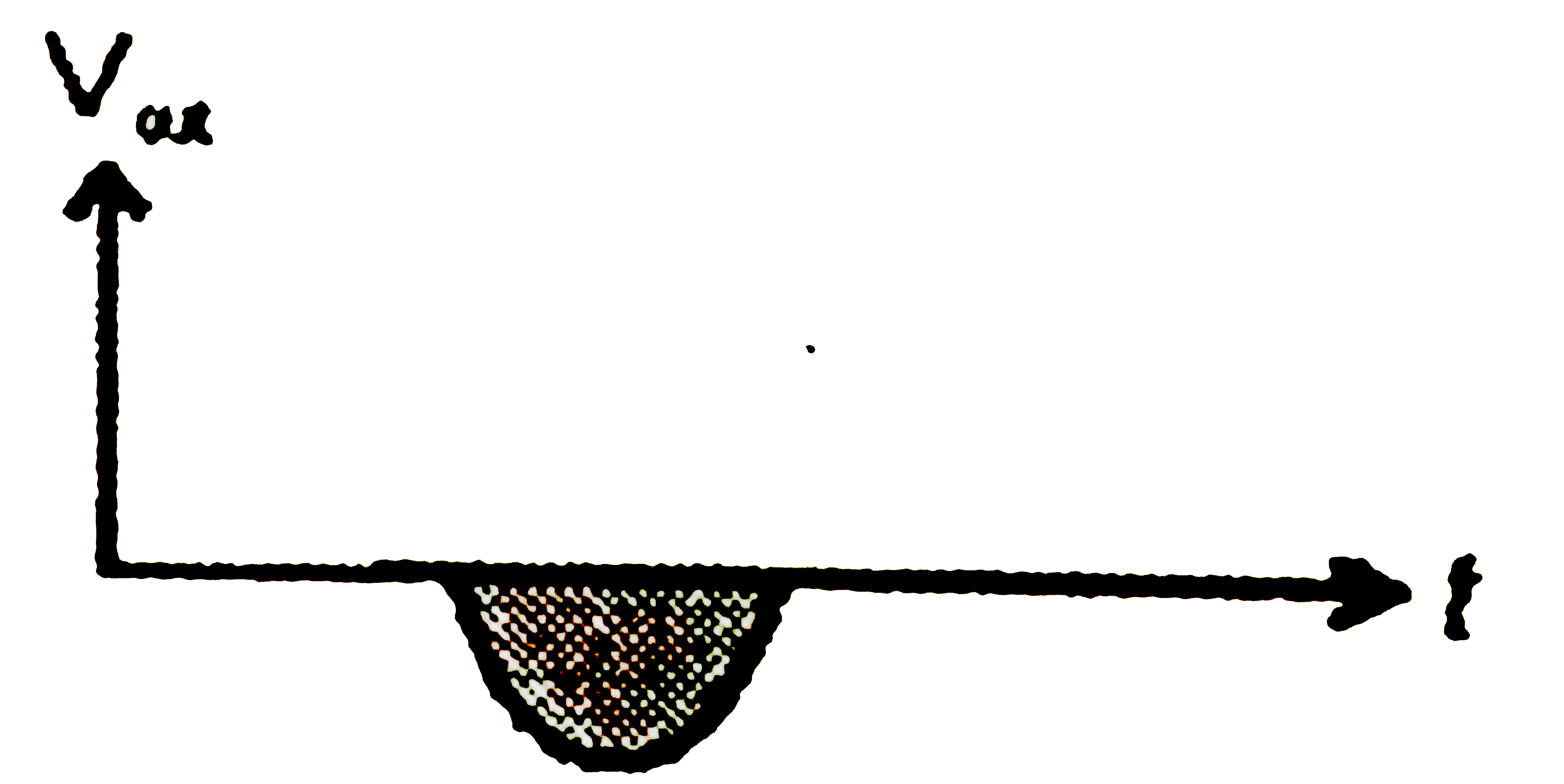 D
D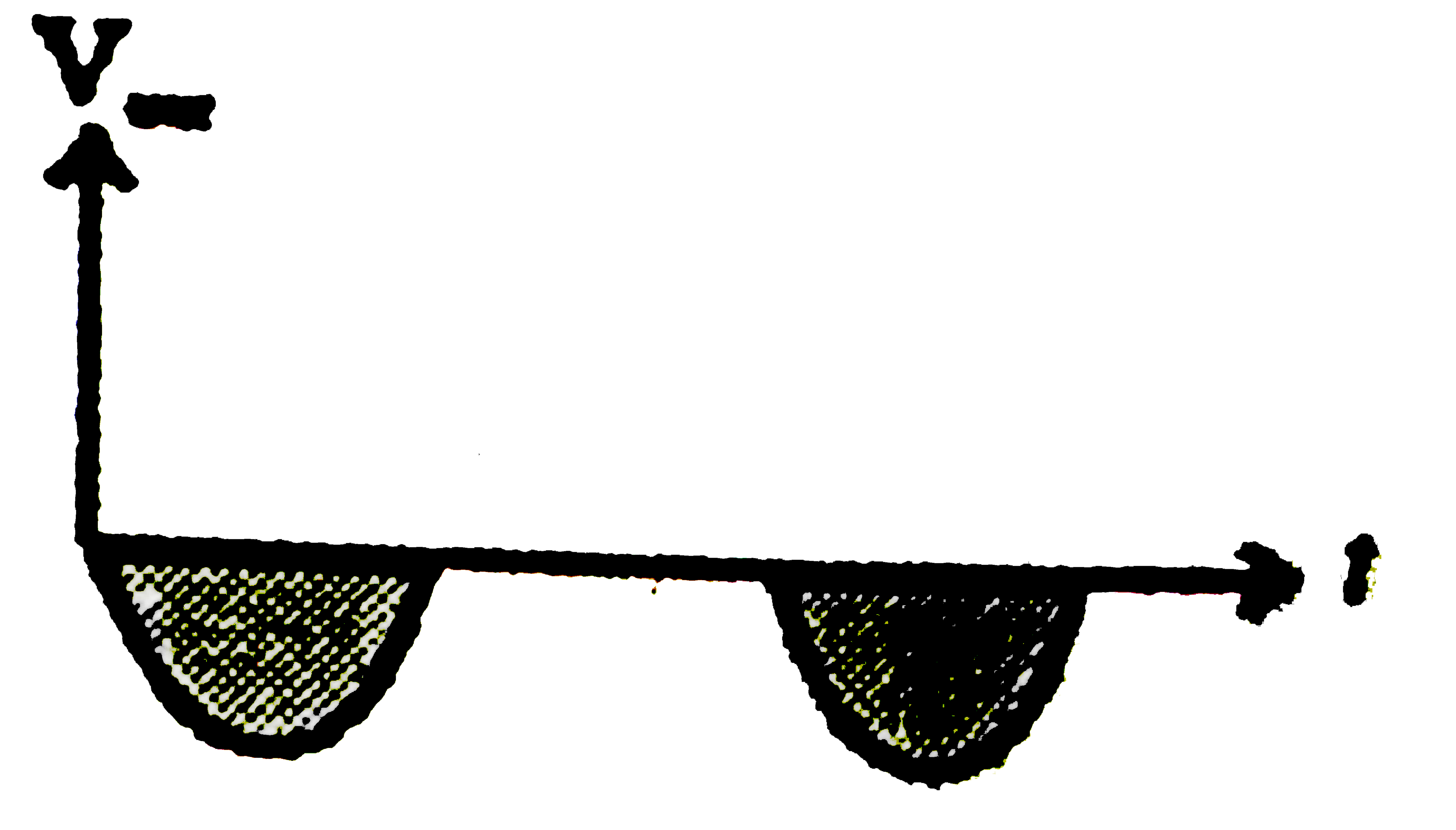
- Question 3 - Select One
A full wave rectifier circuit along with the input and output voltages is shown in the figure
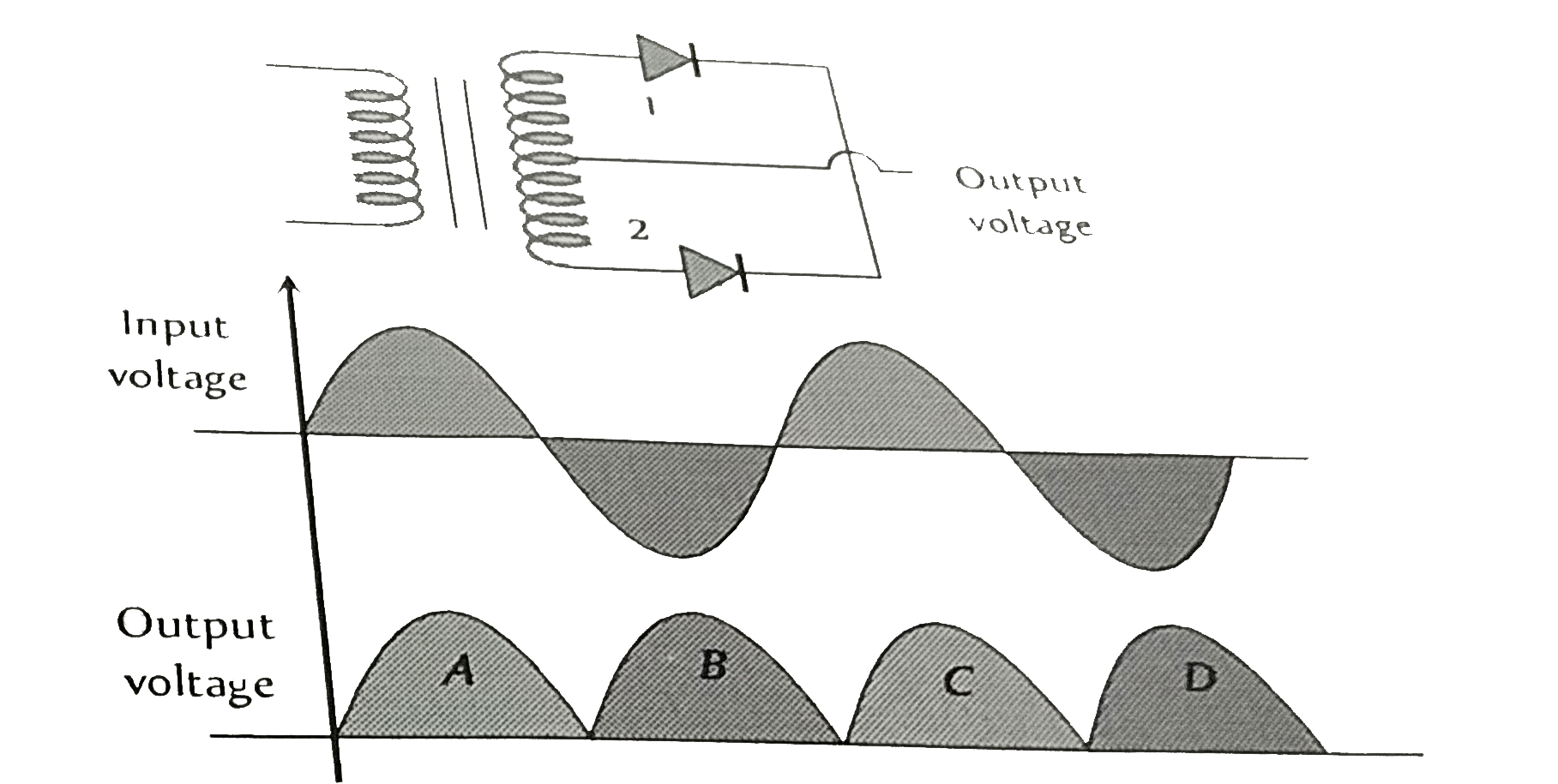
The contribution to output voltage from diode – 2 isAA,CBB,DCB,CDA,D
Draw a circuit diagram of a full-wave rectifier. Explain its working principle. Draw the input/output wave forms indicating clearly the function of the two diode used.
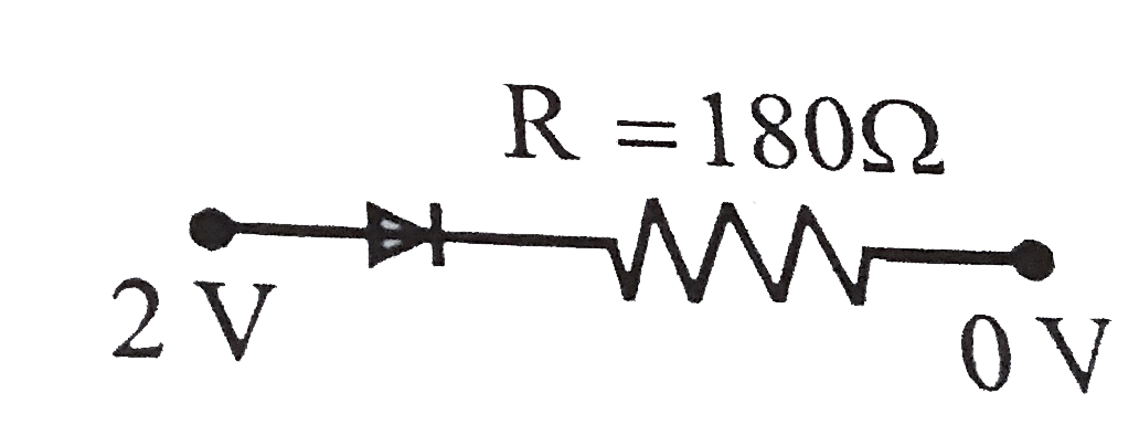
View SolutionAssuming that the silicon diode having resistance of 20Ω, the current through the diode is (knee voltage 0.7 V)
 View Solution
Draw the block diagram of a simple half wave rectifier circuit with respective output wave form
View SolutionThe symbol of a diode is show in the figure

(a) the diode is a _________rectifier diode / photo diode / zener diode
(b) draw the VI characteristics of above diode
(c ) a zener diode with Vz=6.0V is sued for voltage regulation if the unregulated input is 10.0 V what is the value of series resistor R
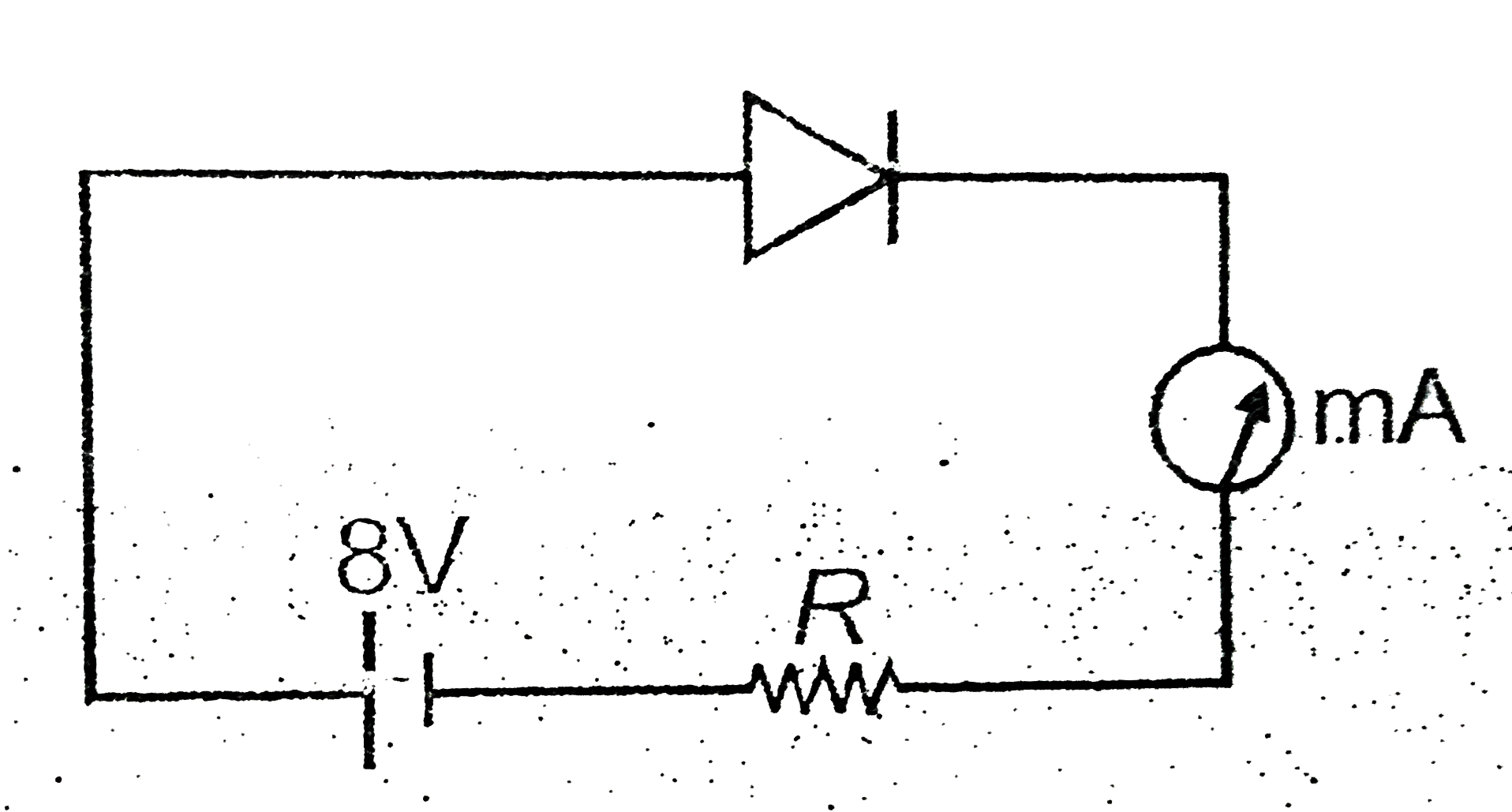
(d) what is the fundamental frequency of the ripple in a full wave rectifier cirucit operating from 50 Hz mainsView SolutionIn the given circuit a silicon diode with knee voltage 0.7V is forward biased with a battery of e.m.f 8V. The current in the circuit is 40 mA. Find the power drop at resistor R and diode.
 View Solution

