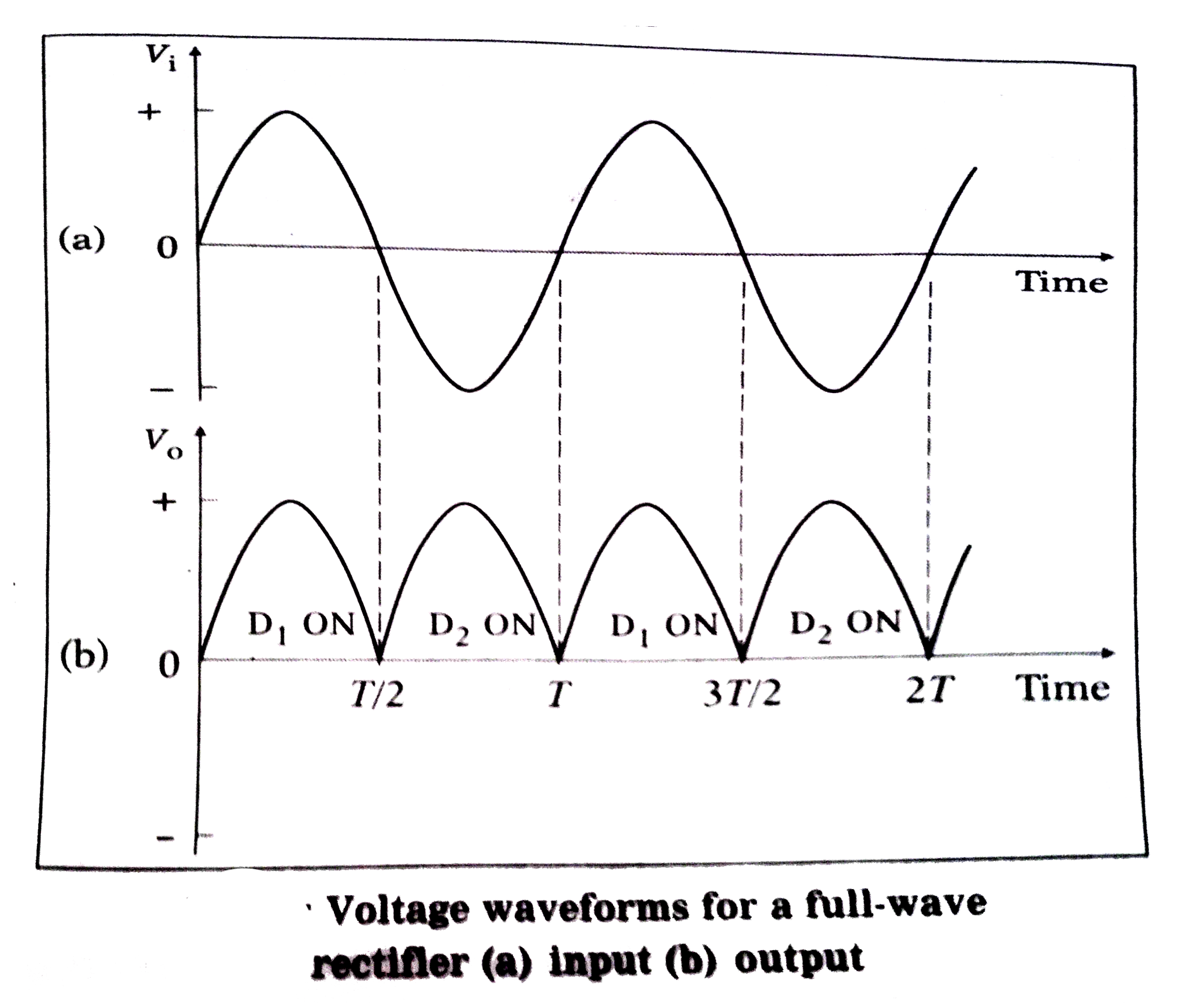
Draw a circuit diagram of a full-wave rectifier. Explain its working principle. Draw the input/output wave forms indicating clearly the function of the two diode used.
Electric circuit : The alternating voltage to be rectified is applied across the primary coil (P1P2) of a transformer with a centretapped secondary coil (S1S2). The terminals S1and S2 of the secondary are connected to the p-regions of two junction diodes D1 and D2, respectively. The centre-tap T is connected to the ground. The load resistance RL is connected across the common n-regions and the ground.
(##NVT21_PHYXIIC11E03001_S01.png width=80%><br>nWork∈g:Afl–−waverectifierrectifies⊥hhalvesofeachcyc≤ofana<ernat∈gvo<a≥.<br>dur∈go≠halfcyc≤ofthe∈put,terminalS_(1)ofthesecondaryispositivewhi≤S_(2)is¬ativewithrespect→theground(thecentre−tapT).Dur∈gthishalfcyc≤,diodeD_(1)isforward−basedandconducts,whi≤diodeD_(2)isreversedbasedanddoes¬conduct.ThedirectionofcurrentI_(L)throughR_(L)is∈thesenseshown.<br>Dur∈gthe≠xthalfcyc≤ofthe∈putvo<a≥,S_(2)becomespositivewhi≤S_(1)becomes¬ativewithrespect→T.DiodeD_(2) now conducts sending the input. This is called full-wave rectification.
The output voltage has a fixed polarity but varies periodically with time between zero and maximum. Fig. 2 shows the input and output voltage waveforms.

Topper's Solved these Questions
- BOOK - NAVNEET PUBLICATION - MAHARASHTRA BOARDCHAPTER - INSTRUMENTS : CONSTRUCTION AND WORKING EXERCISE - Electrons and photons1videos
INSTRUMENTS : CONSTRUCTION AND WORKING
- BOOK - NAVNEET PUBLICATION - MAHARASHTRA BOARDCHAPTER - EXPLANATION, CHARACTERISTICS AND PROPERTIES EXERCISE - Assignments2videos
EXPLANATION, CHARACTERISTICS AND PROPERTIES
- BOOK - NAVNEET PUBLICATION - MAHARASHTRA BOARDCHAPTER - LAWS AND THEORIESEXERCISE - Assignments2videos
LAWS AND THEORIES
Similar Questions
Knowledge Check
- Question 1 - Select One
The output form of full-wave rectifier is
AAn AC voltageBA DC voltageCZeroDA pulsating unidirectional voltage
Draw circuit diagram for a full wave rectifier and show input output voltages.
View SolutionDraw the circuit diagram of half wave rectifier, showing input and output voltages.
View SolutionDraw a neat labelled circuit diagram of full wave rectifier using semiconductor diode.
View SolutionWhat is the output form of full-wave rectifier ?
View SolutionDraw the circuit diagram of transistor as an oscillator and explain its working.
View SolutionDrawa labelled diagram of a full-wave rectifier circuit and briefly explain its working, Show the input-output waveforms.
Or
A student wants to use two p-n junction diodes to convert a.c. into d.c. Draw the labelled circuit diagram she would use and explain how it works.View SolutionDraw the output wave form across the resistor
 View Solution

