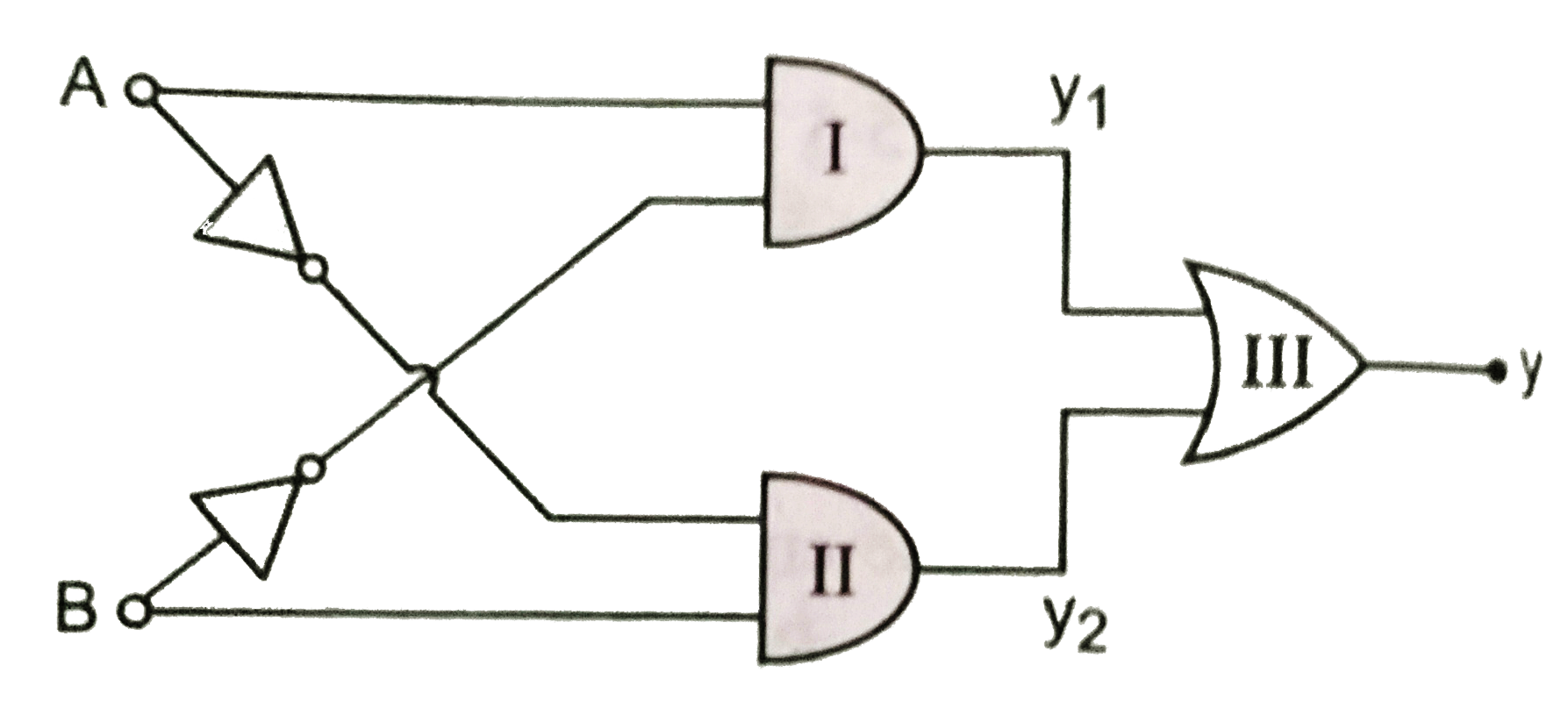
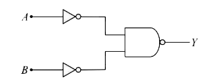
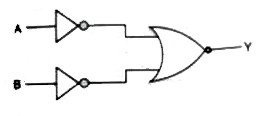
Identify the logic gate equivalent to the circuit shown in the Fig.Draw the truth table for all possible values of inputs A and B.
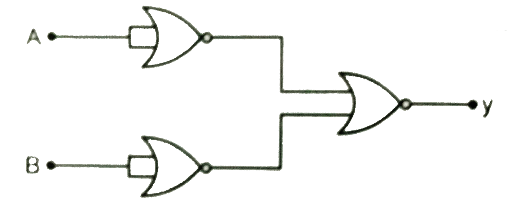
Video Solution
|
Answer
Step by step video & image solution for Identify the logic gate equivalent to the circuit shown in the Fig.Draw the truth table for all possible values of inputs A and B. by Physics experts to help you in doubts & scoring excellent marks in Class 12 exams.
Updated on:21/07/2023Topper's Solved these Questions
- ELECTRONIC DEVICESBOOK - PRADEEPCHAPTER - ELECTRONIC DEVICESEXERCISE - LONG QUESTION ANSWER
2 Videos
- ELECTRONIC DEVICESBOOK - PRADEEPCHAPTER - ELECTRONIC DEVICESEXERCISE - PROBLEMS FOR PRACTICE
7 Videos
- ELECTRONIC DEVICESBOOK - PRADEEPCHAPTER - ELECTRONIC DEVICESEXERCISE - HIGHER ORDER THINKING SKILLS
1 Videos
- ELECTROMAGNETIC WAVESBOOK - PRADEEPCHAPTER - ELECTROMAGNETIC WAVESEXERCISE - II Focus multiple choice question
5 Videos
- ELECTROSTATICSBOOK - PRADEEPCHAPTER - ELECTROSTATICSEXERCISE - ASSERTION-REASON TYPE QUESTIONS
2 Videos
Similar Questions
Knowledge Check
Identify the logic gate G in the combination of gates shown in fig. The truth table is shown here
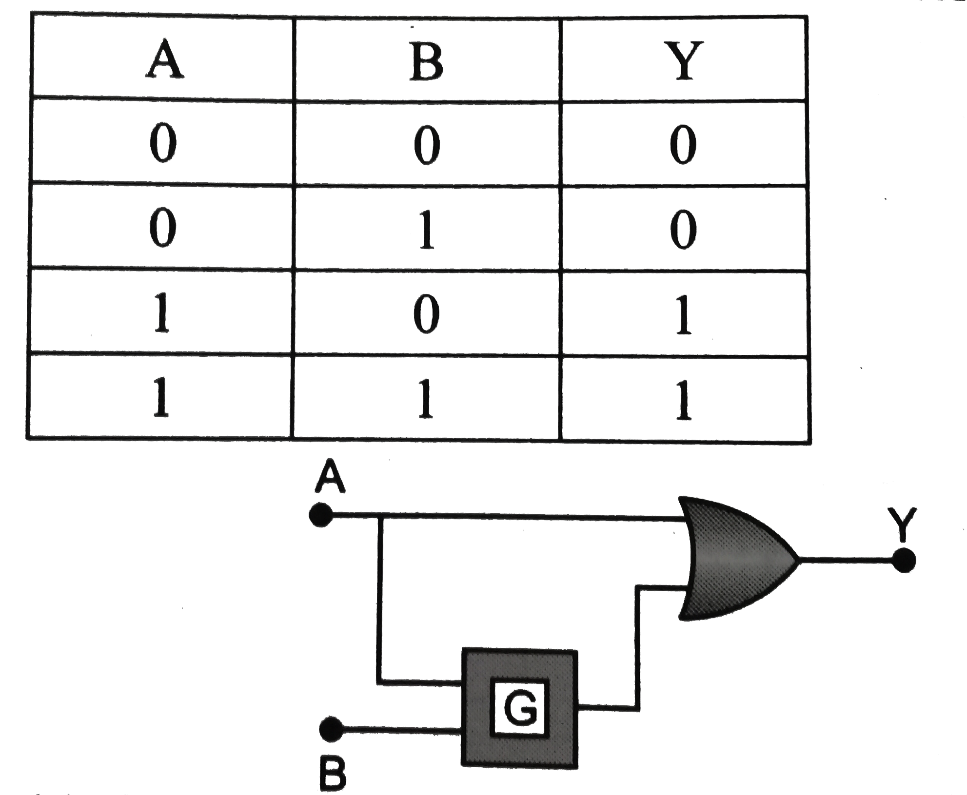 AOR gateBAND gateCNOTgateDNOR gate
The truth table of a logic gate is a table
Agiving only the true numbersBrejecting only the wrong numbersCgiving the relation between the input and output variables of a logic gateDwhich gives all the possible input logic levels and the corresponding resultant logic levels in the outputFor the logic circuit shown, the truth table is
 A
A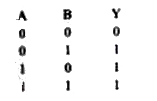 B
B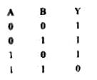 C
C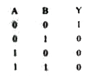 D
D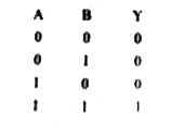
Identify the logic gates marked P and Q in the circuit Fig. Write the truth table for this combination.

View SolutionWrite the truth table for the circuit shown in Fig. Name the gate so formed.
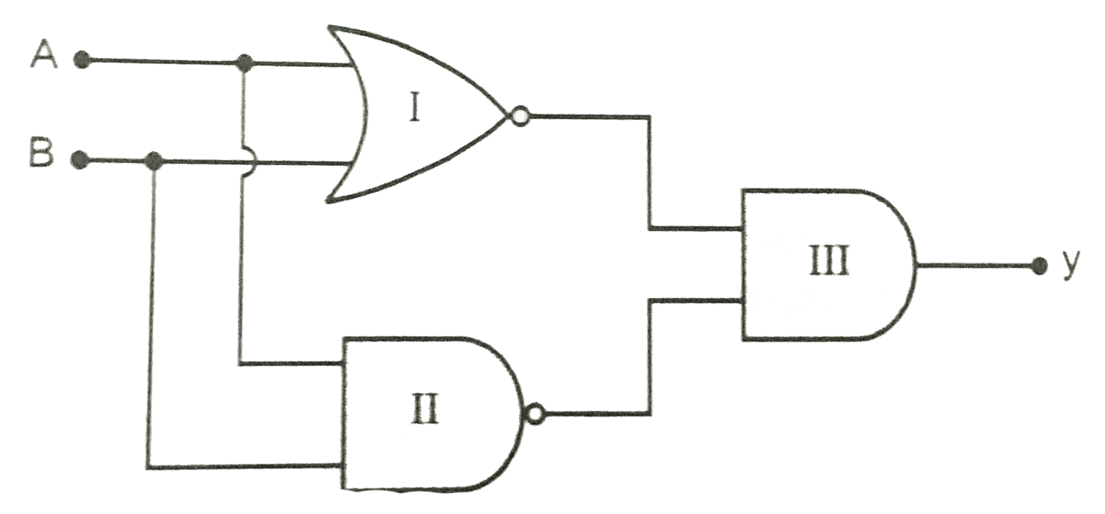
View Solutionidentify the equivalent gate for the following cirucit and write its truth table

View SolutionFor given logic gate truth table is
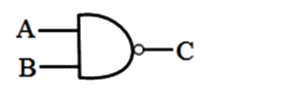
View SolutionThe truth table for the following logic circuit is

View Solution

