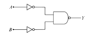
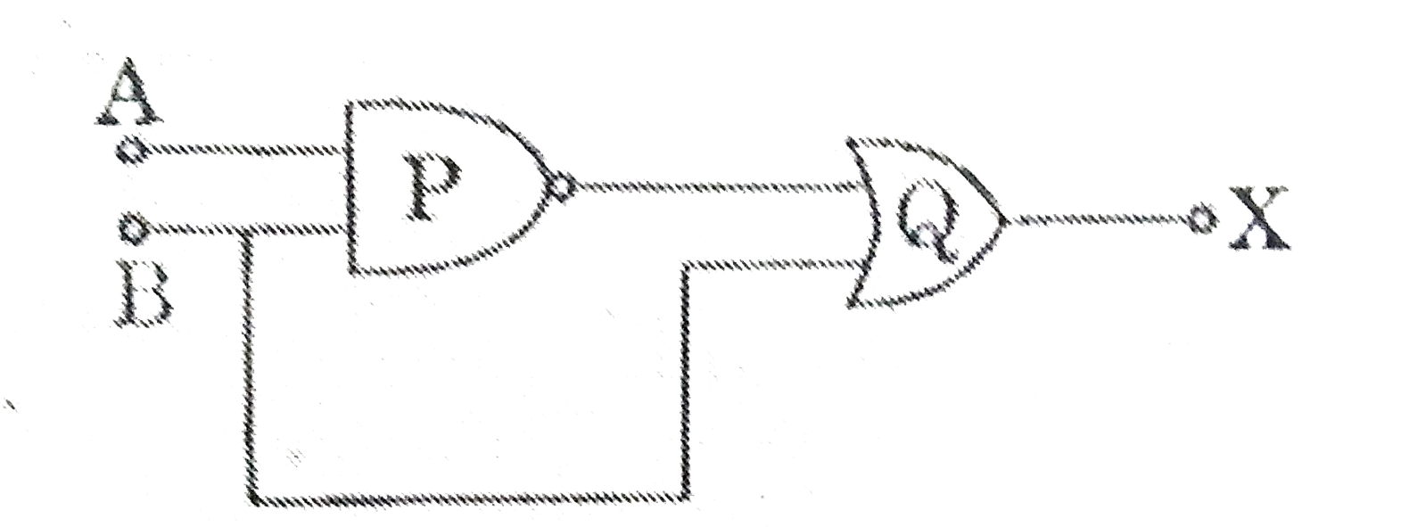
Identify the logic gates marked P and Q in the given logic circuit. Write down the Boolean expression for this logic circuit and truth table.

Here gate P is OR gate and gate Q is NAND gate. The Boolean expression for this logic circuit is
y=¯¯¯¯¯¯¯¯¯¯¯¯¯¯¯¯¯¯¯(A+B).B=¯¯¯¯¯¯¯¯¯¯¯A+B+¯¯¯B
Truth table of this logic circuit is given below
∣∣
∣
∣
∣
∣
∣∣AB(A+B)(A+B.)By=¯¯¯¯¯¯¯¯¯¯¯¯¯¯¯¯¯¯¯(A+B).B00001011101010111110∣∣
∣
∣
∣
∣
∣∣
Topper's Solved these Questions
- BOOK - PRADEEPCHAPTER - ELECTRONIC DEVICESEXERCISE - LONG QUESTION ANSWER2videos
ELECTRONIC DEVICES
- BOOK - PRADEEPCHAPTER - ELECTRONIC DEVICESEXERCISE - PROBLEMS FOR PRACTICE7videos
ELECTRONIC DEVICES
- BOOK - PRADEEPCHAPTER - ELECTRONIC DEVICESEXERCISE - HIGHER ORDER THINKING SKILLS1videos
ELECTRONIC DEVICES
- BOOK - PRADEEPCHAPTER - ELECTROMAGNETIC WAVESEXERCISE - II Focus multiple choice question5videos
ELECTROMAGNETIC WAVES
- BOOK - PRADEEPCHAPTER - ELECTROSTATICSEXERCISE - ASSERTION-REASON TYPE QUESTIONS2videos
ELECTROSTATICS
Similar Questions
Knowledge Check
- Question 1 - Select One
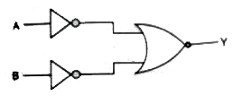
For the logic circuit shown, the truth table is
 A
A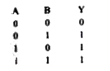 B
B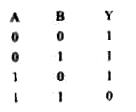 C
C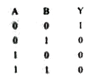 D
D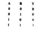
- Question 2 - Select One
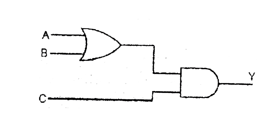
For the logic circuit shown the boolean relation is-AY=ABCBY=A+BCCY=(A+B)CDY=AB+C
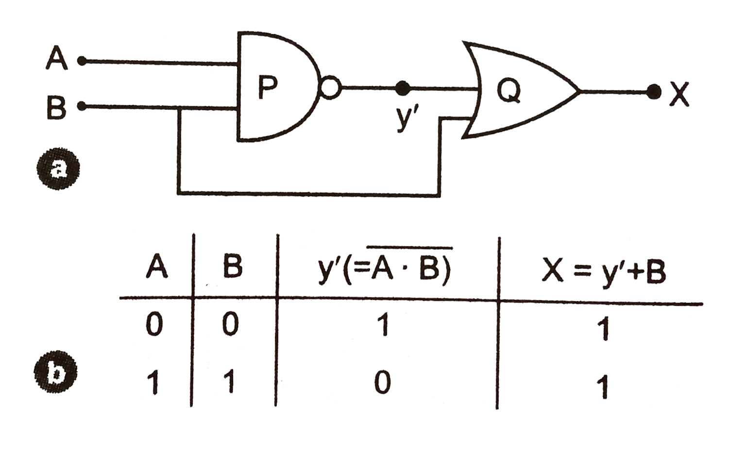
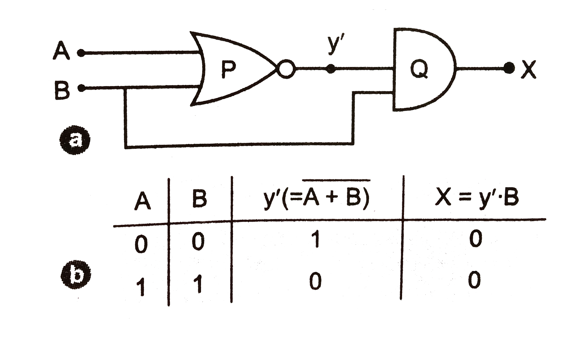
Identify the logic gates marked P and Q in the given logic circuit Fig. Write down then output at X for the inputs
(i) A=0,B=0 and (ii) A=1,B=1.
 View Solution
(i) Identify the logic gates marked P and Q in the given logic circuit Fig.

(ii) Write down the output at X for the inputs A=0,B=0 and A=1,B=1.View Solution(i) Identify the logic gates marked P and Q in the given logic circuit.
(ii) Write down the output at X for the inputs A = 0 , B = 0 and A = 1 , B = 1.View SolutionIdentify the logic gate markeed P and Q in the given logic circuit Fig . Write down the output at X for the inputs
(i) A=0,B=0 and (ii) A=1,B=1.
 View Solution
Identify the logic gates marked P and Q in the circuit Fig. Write the truth table for this combination.
 View Solution
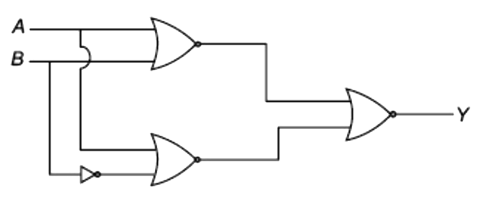
The output of the given logic circuit is
 View Solution


