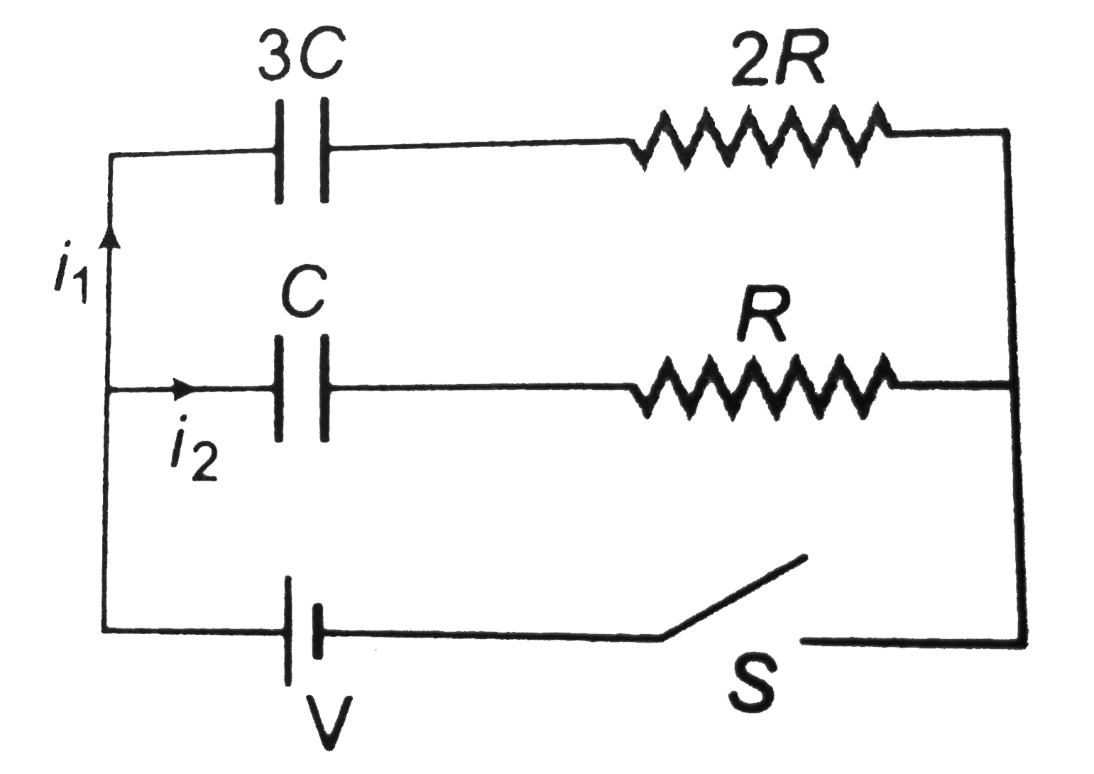
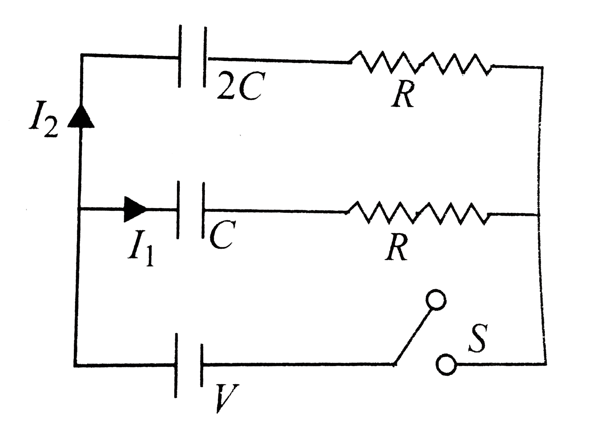
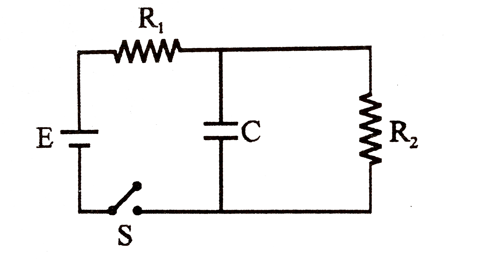
In the circuit shown switch S is closed at t=0. Let i1 and i2 be the current at any finite time t then the ratio i1i2
is constant
increases with line
decrease with time
first increases then decreases
The correct Answer is:B
i1=(V2R)e−t6CR
∴i2=(VR)e−tCR
∴i1i2=e5t6CR2
we can that this ratio is increasing with time.
Topper's Solved these Questions
- BOOK - DC PANDEYCHAPTER - CAPACITORSEXERCISE - OBJECTIVE_TYPE1videos
CAPACITORS
- BOOK - DC PANDEYCHAPTER - CAPACITORSEXERCISE - OBJECTIVE_TYPE1videos
CAPACITORS
- BOOK - DC PANDEYCHAPTER - ATOMSEXERCISE - MEDICAL ENTRANCES GALLERY42videos
ATOMS
- BOOK - DC PANDEYCHAPTER - COMMUNICATION SYSTEMEXERCISE - Subjective11videos
COMMUNICATION SYSTEM
Similar Questions
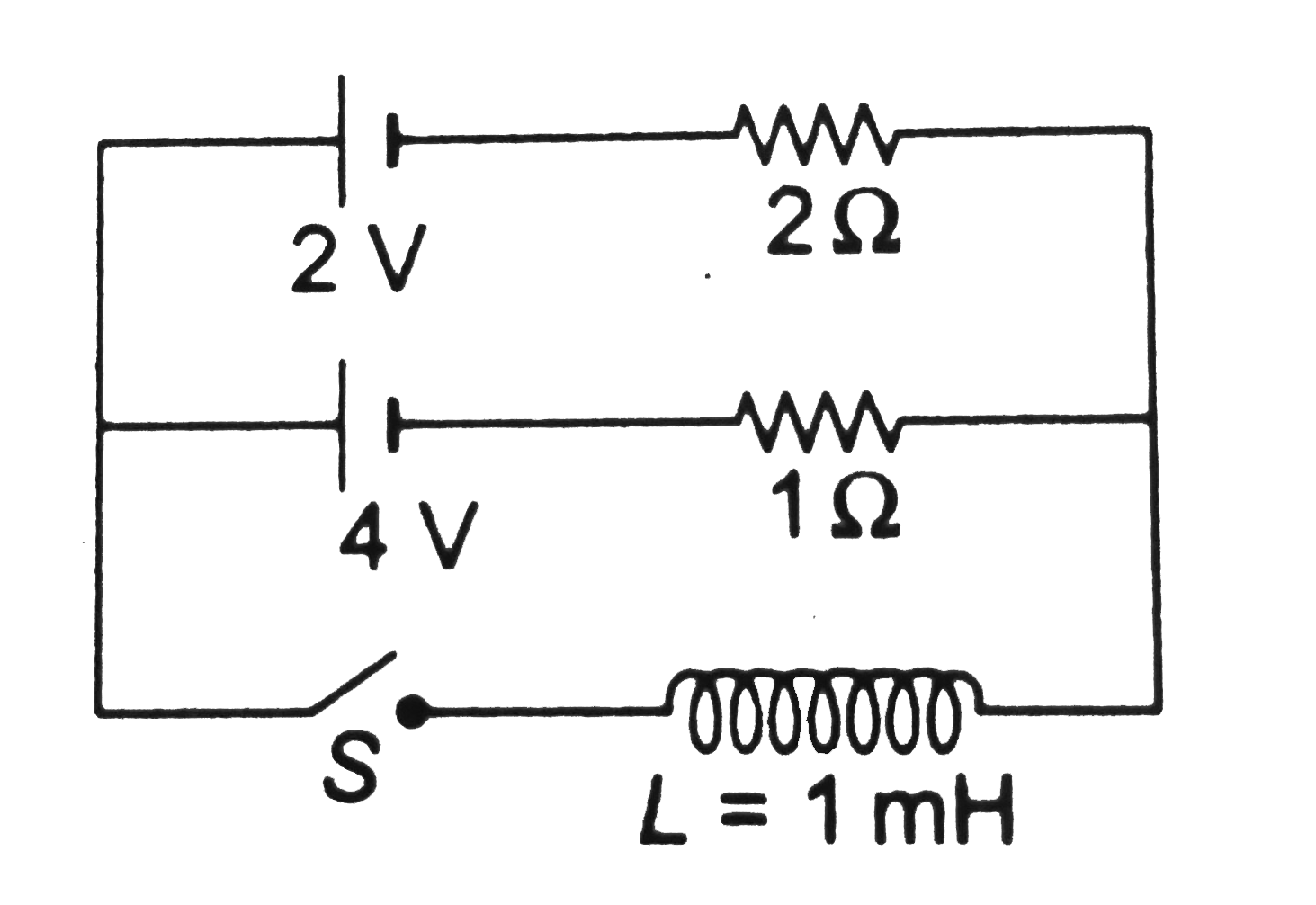
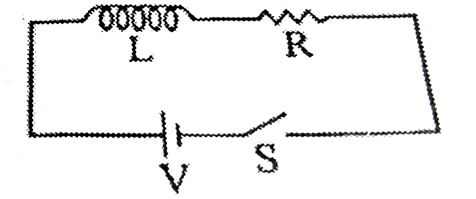
In the circuit shown, switch S is closed at time t=0. Find the current through the inductor as a function of time t.
 View Solution
In the circuit shown in fig switch S is closed at time t =0.
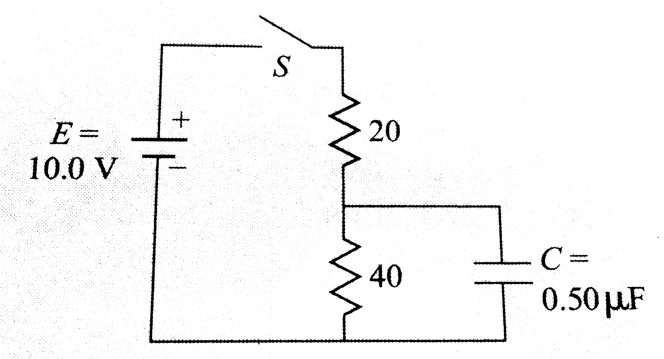
a. What is the current I0 leacing the battery at t=0, immediately after the switch is closed?
b. What is the current I "long time" later?
c. What charge has accmulated on the capacitor after this long time?
d. If, finally, swtich S is opened again, how long will it take after the switch is opened for the capactior to lose 80% of its charge?View Solution
Knowledge Check
- Question 1 - Select One
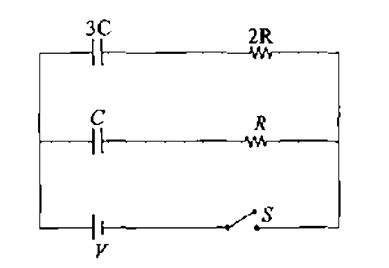
In the circuit shown, switch Sis closed att=O. Let i1andi2be the current at any finite time I, then the ratio i1/i2 is
 AConstantBIncreases with timeCDecreases with timeDFirst increases and then decreases
 - Question 2 - Select One
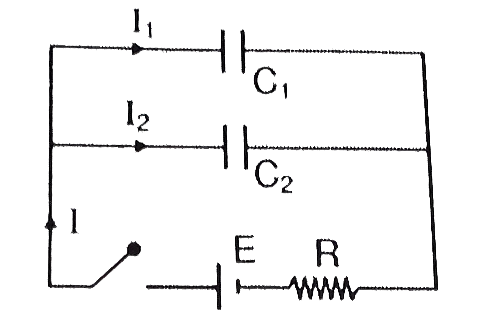
In the circuit shwon in fig. switch S is closed at time t = 0. Let I1andI2 be the currents at any finite time t, then the ratio I1/I2
 Ais constantBincreases with timeCdecreases with timeDfirst increases, then decreases
 - Question 3 - Select One
In the circuit shown, the switch is closed at t=0, the currents I1,I2 and I3 are
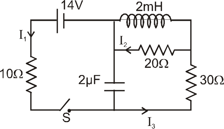 A1.4A,0,0B1.4 A,0.70 A,0.70 AC0,0,0D1.2A,0.6A,0.6A
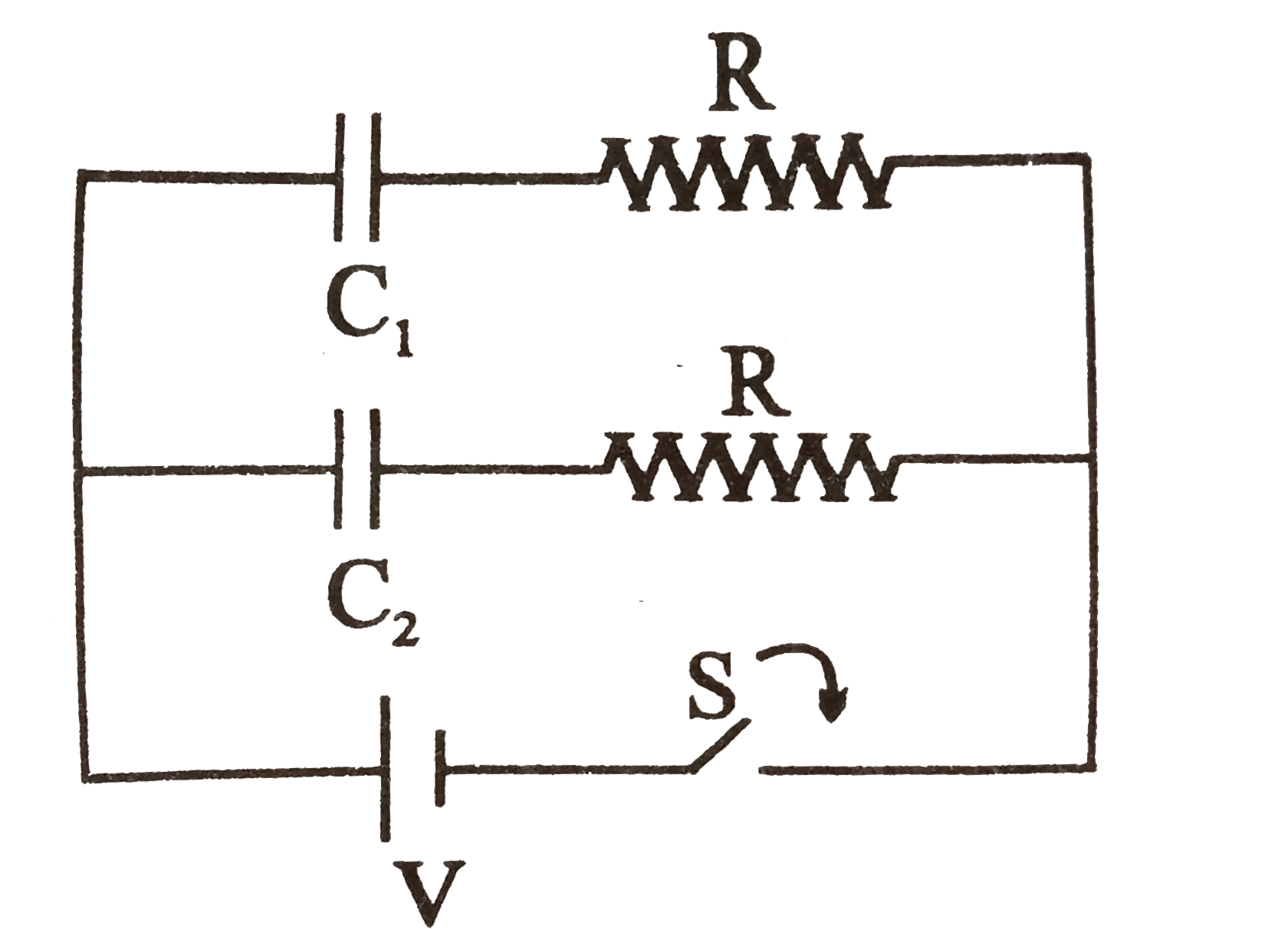
In the ciruit shown in figured C1=2C2. SwitchS is closed at timt t=0.Let i1 and i2 be currents flowing through C1 and C2 at any time t, then the ratioi1/i2
 View Solution
In the circuit shown in figure switch S is closed at time t=0
Current I from the battery at time t is given byView SolutionIn the circuit as shown in figure the switch is closed at t=0.
At the instant of closing the switchView SolutionIn the circuit shown below the switch is closed at t=0. For 0<t<R(C1+C2), the current I1 in the capacitor C1 in terms of total current I is
 View Solution
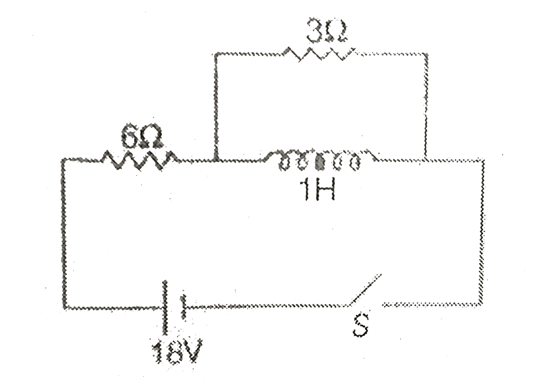
In adjacent circuit, switch S is closed at t = 0. The time at which current in the circuit becomes half of the steady current is
 View Solution

