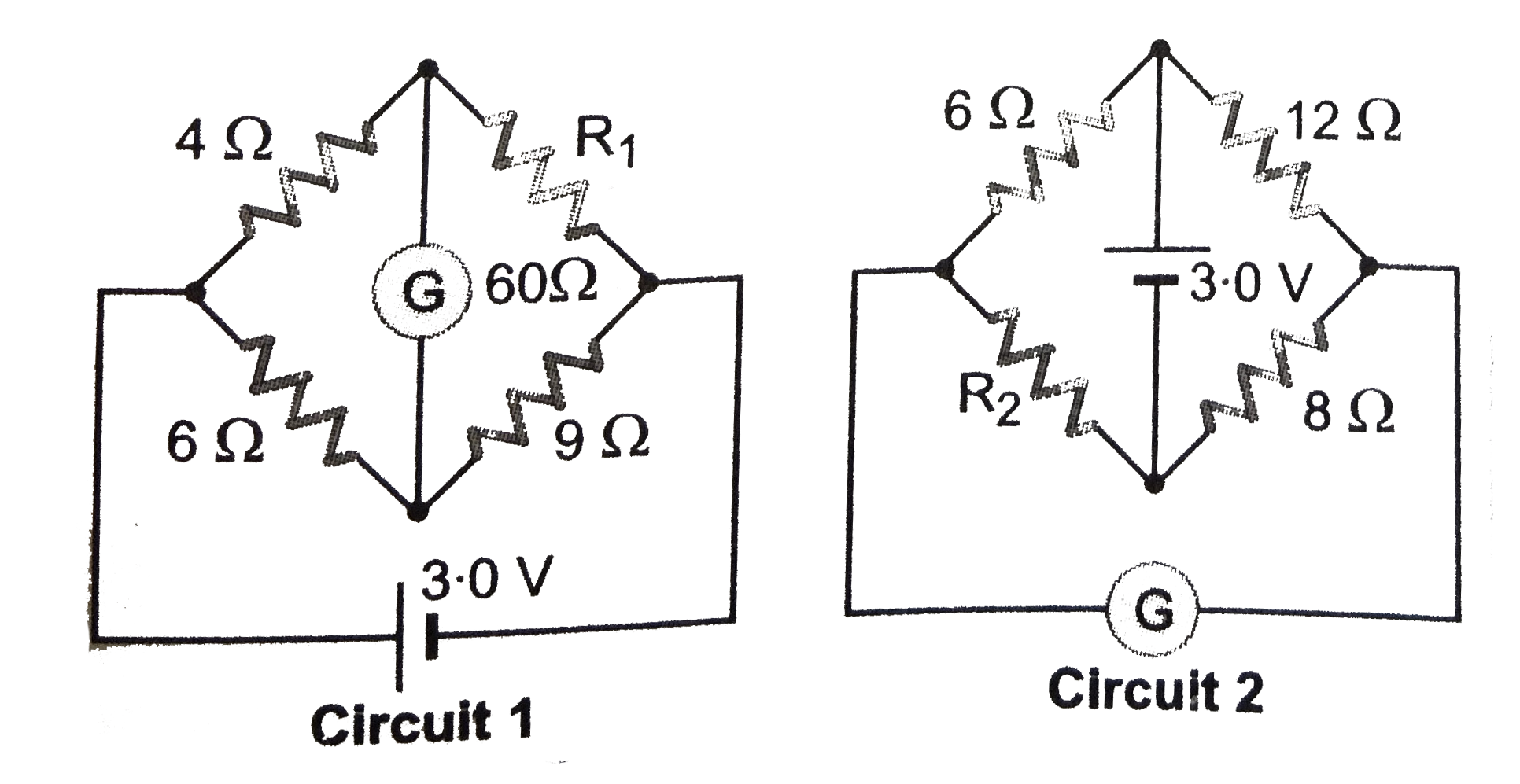
The galvanometer, in each of the two given circuits does not show any deflection. Find the ratio of the resistors and used in these two circuits.
Video Solution
Text Solution
In circuit 1, the Wheatstone bridge is in balanced state so,
or
In circuit 2, the positions of galvanometer and battery are interchanged but the galvanometer shows no defelction, means the bridge is in balanced state, so
or
|
Updated on:21/07/2023
Topper's Solved these Questions
- BOOK - PRADEEPCHAPTER - CURRENT ELECTRICITYEXERCISE - Conceptual Problems3videos
CURRENT ELECTRICITY
- BOOK - PRADEEPCHAPTER - CURRENT ELECTRICITYEXERCISE - Very short Q/A7videos
CURRENT ELECTRICITY
- BOOK - PRADEEPCHAPTER - COMMUNICATION SYSTEMSEXERCISE - MODEL TEST PAPER-29videos
COMMUNICATION SYSTEMS
- BOOK - PRADEEPCHAPTER - DUAL NATURE OF RADIATION AND MATTEREXERCISE - Exercise191videos
DUAL NATURE OF RADIATION AND MATTER
Similar Questions
Knowledge Check
- Question 1 - Select One
In the given circuit, the galvanmeter G will show zero deflection if
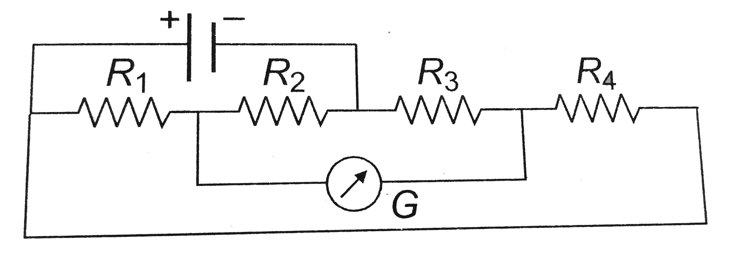 AR1R2=R3R4BR1R3=R2R4CR1R4=R2R3Dgalvanometer can't have zero current for any relation between the resistances
 - Question 2 - Select One
In the circuit shown in the given figure, the resistances R1andR2 are respectively
 A14Ωand40ΩB40Ωand44ΩC40Ωand30ΩD14Ωand30Ω
 - Question 3 - Select One
Power factor of an L-R series circuit is 0.6 and that of a C-R series circuit is 0.5. If the element (L. C, and R) of the two circuits are joined in series the power factor of this circuit is found to be 1. The ratio of the resistance in the L-R circuit to the resistance in the C-R circuit is
A6/5B5/6C43√3D3√34
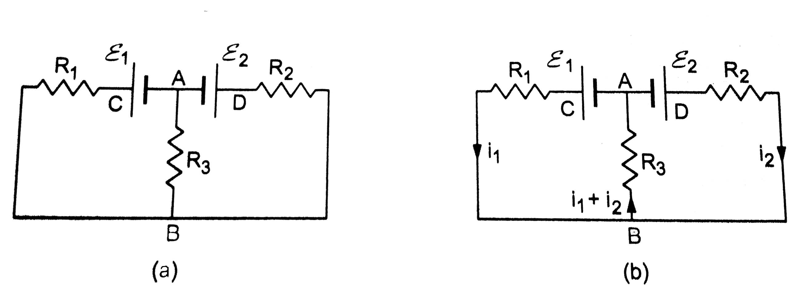
Find the currents going through the three resistors R_(v),R_(2)andR_(3) in the circuit of figure.
 View Solution
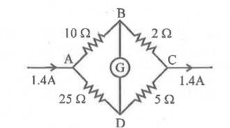
In the given circuit, when the galvanometer G shows no deflection, the current in the 5Ω resistance is ,
 View Solution
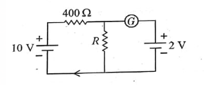
If the galvanometer G does not show any deflection in the circuit shown, the value of R is given by :
 View Solution
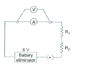
In an experiment to find the equivalent resistance of a series combination of two resistors R1 and R2,a student uses the circuit shown here. Will the circuit give the correct reading for current I and voltage V ? Justify your answer.
 View Solution
In the given circuit, find the value of R :
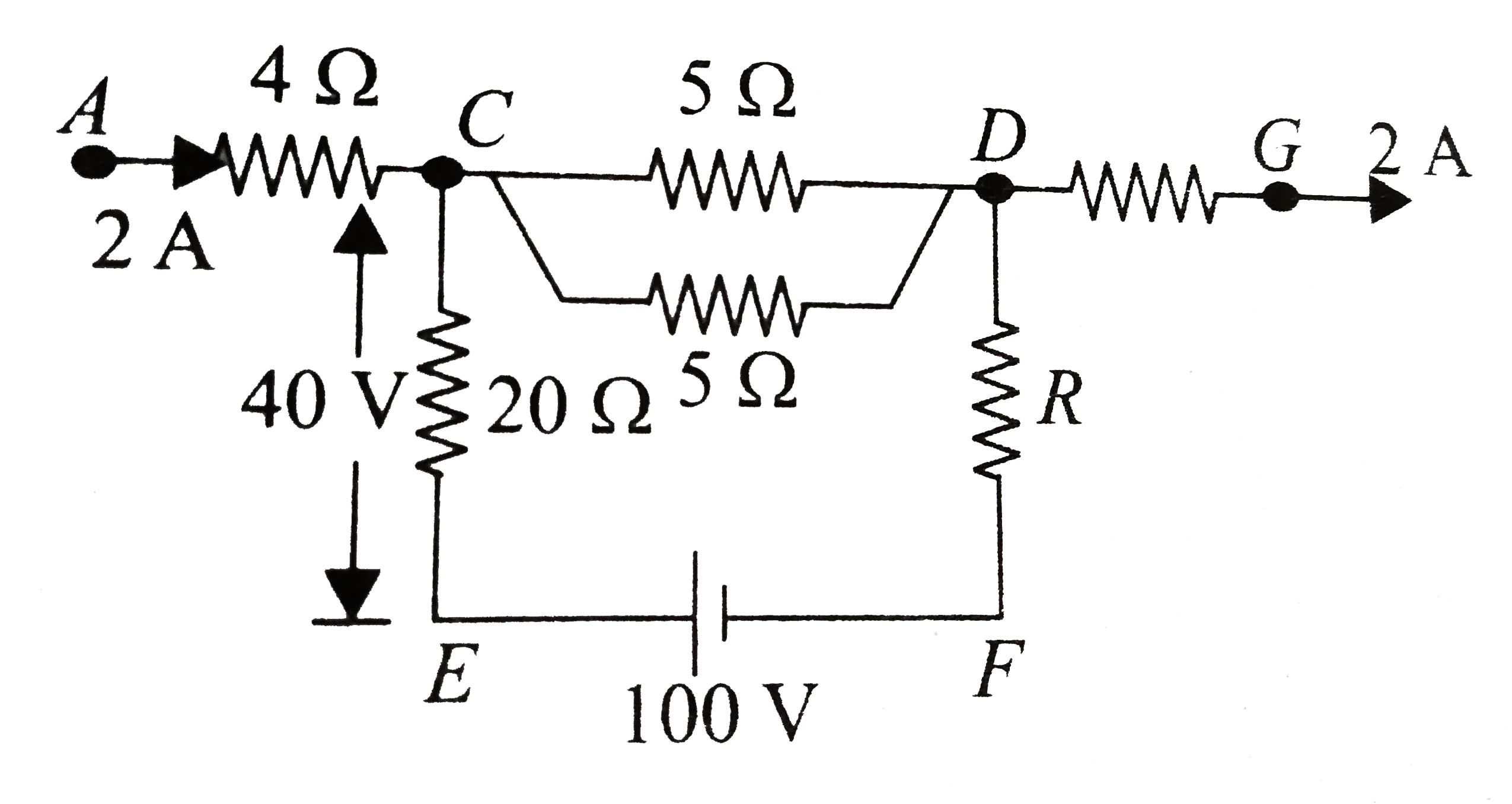 . View Solution


