Draw the approximate voltage vector diagrams in the electric circuits shown in figure. a,b. The external voltage V is assumed to be alternating harmonically with frequency ω


(b)tanφ=ωL−1ωCR=−ve
as ω2<1LC
 ,
, 
Topper's Solved these Questions
- OSCILLATIONS AND WAVESBOOK - IE IRODOV, LA SENA & SS KROTOVCHAPTER - OSCILLATIONS AND WAVESEXERCISE - Elastic Waves
39 Videos
- OSCILLATIONS AND WAVESBOOK - IE IRODOV, LA SENA & SS KROTOVCHAPTER - OSCILLATIONS AND WAVESEXERCISE - Electromagnetic Waves, Radiation
36 Videos
- OSCILLATIONS AND WAVESBOOK - IE IRODOV, LA SENA & SS KROTOVCHAPTER - OSCILLATIONS AND WAVESEXERCISE - Electromagnetic Waves, Radiation
36 Videos
- OPTICSBOOK - IE IRODOV, LA SENA & SS KROTOVCHAPTER - OPTICSEXERCISE - Exercise
2 Videos
- PHYSICAL FUNDAMENTALS OF MECHANICSBOOK - IE IRODOV, LA SENA & SS KROTOVCHAPTER - PHYSICAL FUNDAMENTALS OF MECHANICSEXERCISE - Relativistic Mechanics
49 Videos
Similar Questions
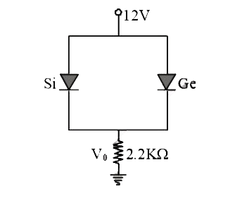
In the circuit shown in figure, Voltage V0 is–
View SolutionDraw the approcimate vector diagrams of currents in the circuits shown in figure. The voltage applied across the points A and B is assmed to be sinosoidal, the parameters of each circuit are so chosen that the total current I0 lags in phase behind the external voltage by an angle φ.

View Solution
Knowledge Check
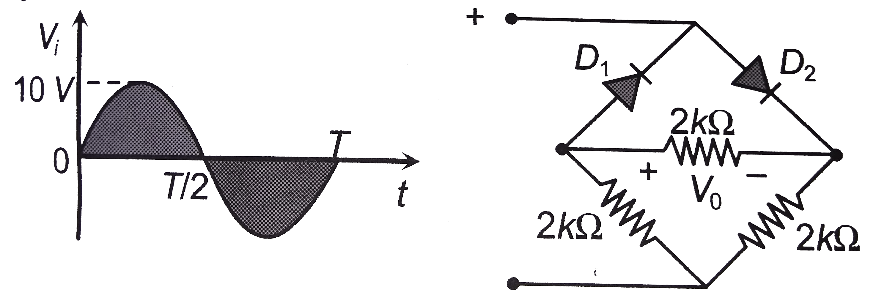
In the circuit shown in figure the maximum output voltage V0 is
 A0VB5VC10VD5√2V
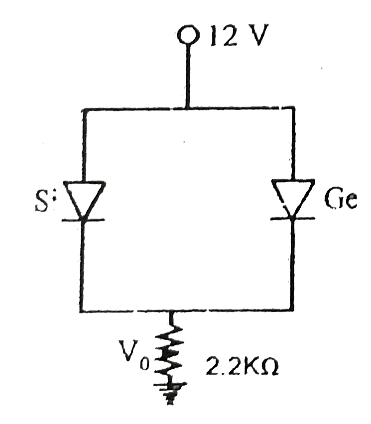
In the circuit shown in figure, Voltage V0 is
 A11.7 voltB11.3 voltC0DNone
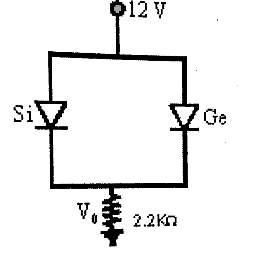
In the circuit shown infigure, voltage V0 is,A11.7 voltB11.3 voltC0DNone of these
For the circuit shown in figure , determine the unknown voltage drop V1.
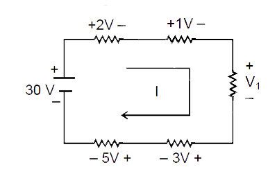
View SolutionFor the circuit shown in figure, determine the unknown voltage drop V1.
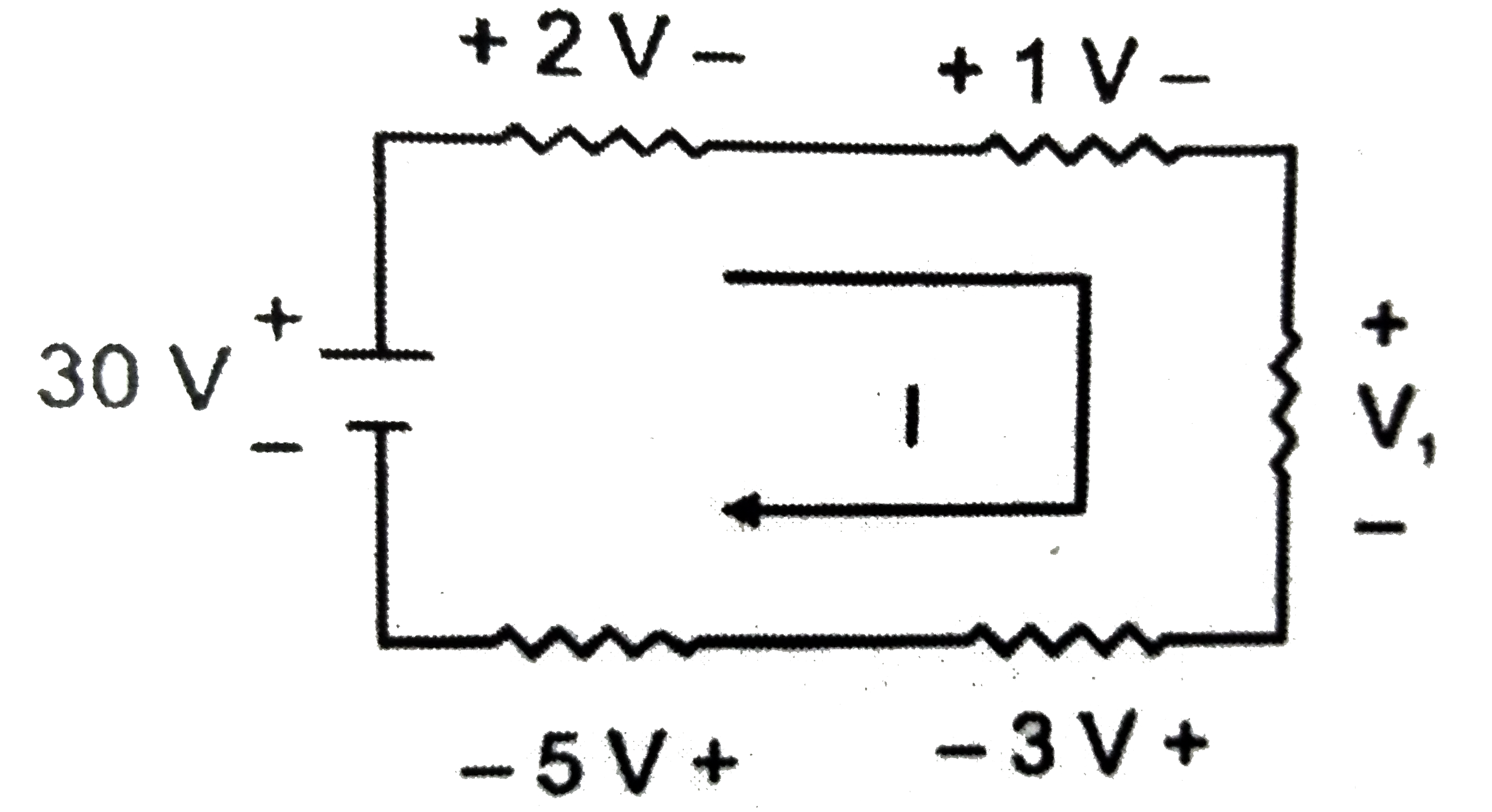
View SolutionFor the circuit shown in figure, determine the voltage across 4Ω resistors in volt ?

View SolutionWhat is the value of output voltage V0 in the circuit shown in the figure ?
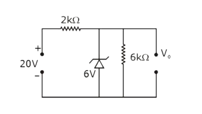
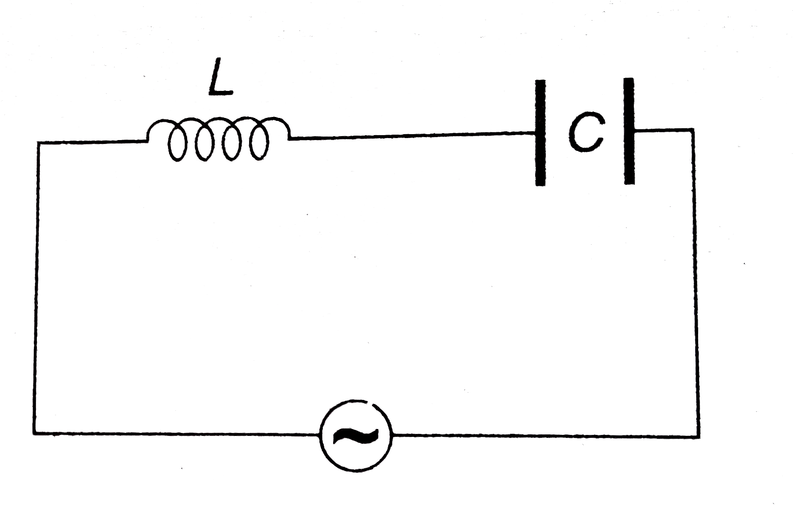
View SolutionIn the circuit shown in figure the voltage in L and in C are
 .
.
View Solution
