In the circuit shown in figure, Voltage V0 is–
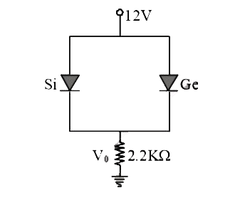
11.7 volt
11.3 volt
0
none
The correct Answer is:A
Step by step video & image solution for In the circuit shown in figure, Voltage V_0 is– by Physics experts to help you in doubts & scoring excellent marks in Class 12 exams.
Updated on:21/07/2023Topper's Solved these Questions
- SEMI CONDUCTOR AND LOGIC GATESBOOK - MOTIONCHAPTER - SEMI CONDUCTOR AND LOGIC GATESEXERCISE - EXERCISE 3
34 Videos
- SEMI CONDUCTOR AND LOGIC GATESBOOK - MOTIONCHAPTER - SEMI CONDUCTOR AND LOGIC GATESEXERCISE - EXERCISE 3
34 Videos
- ROTATIONAL MOTION BOOK - MOTIONCHAPTER - ROTATIONAL MOTION EXERCISE - Exercise - 3 ( Section-B )
24 Videos
- SIMPLE HARMONIC MOTIONBOOK - MOTIONCHAPTER - SIMPLE HARMONIC MOTIONEXERCISE - EXERCISE -3 Section - B Previous Year Problems | JEE MAIN
23 Videos
Similar Questions
Knowledge Check
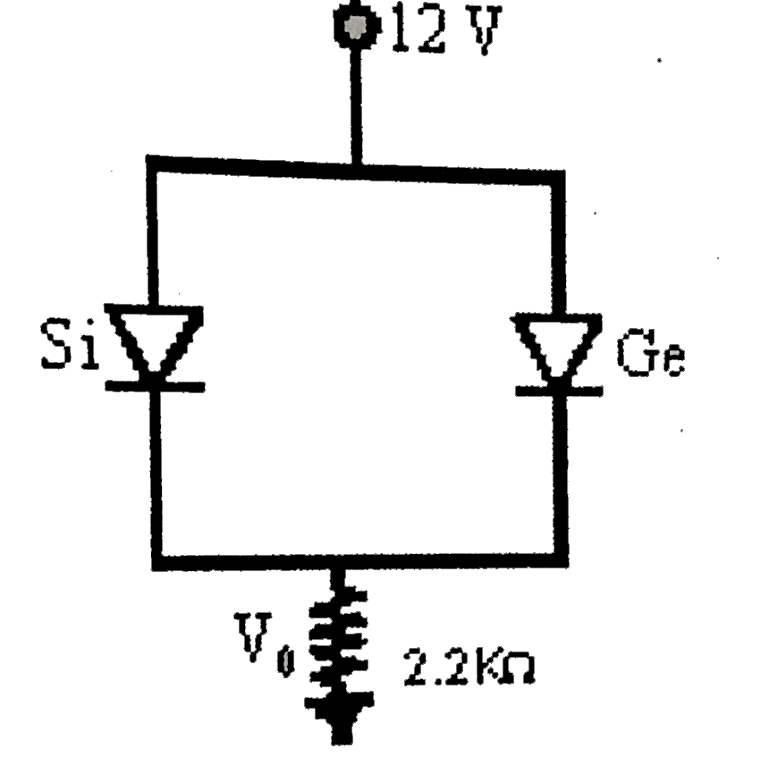
In the circuit shown infigure, voltage V0 is,A11.7 voltB11.3 voltC0DNone of theseIn the circuit shown in figure , V must be
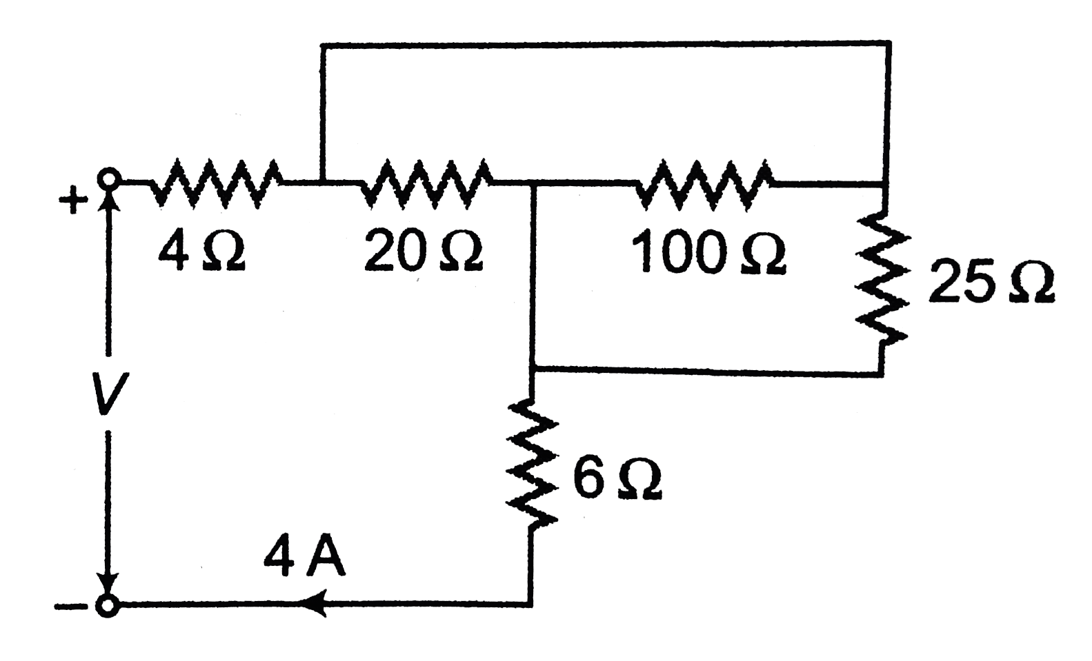 A50VB80VC100VD1290V
In the circuit shown in figure the voltage in L and in C are
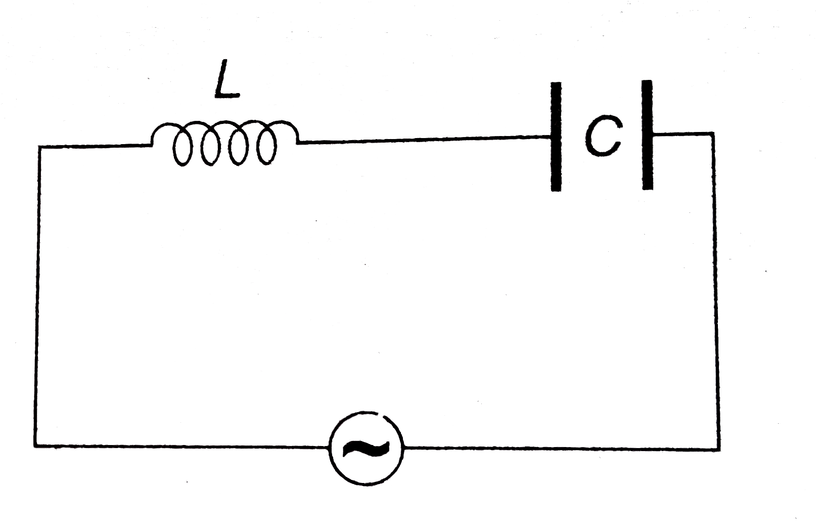 .Ain phaseBout of phase by 90∘Cout of phase by 180∘Din a phase difference which depends upon the values of L C .
In the circuit shown in Fig.a voltage V is connected across lamp L. What changes would occur at lamp and the voltage V, if the resistance R is reduced in value?
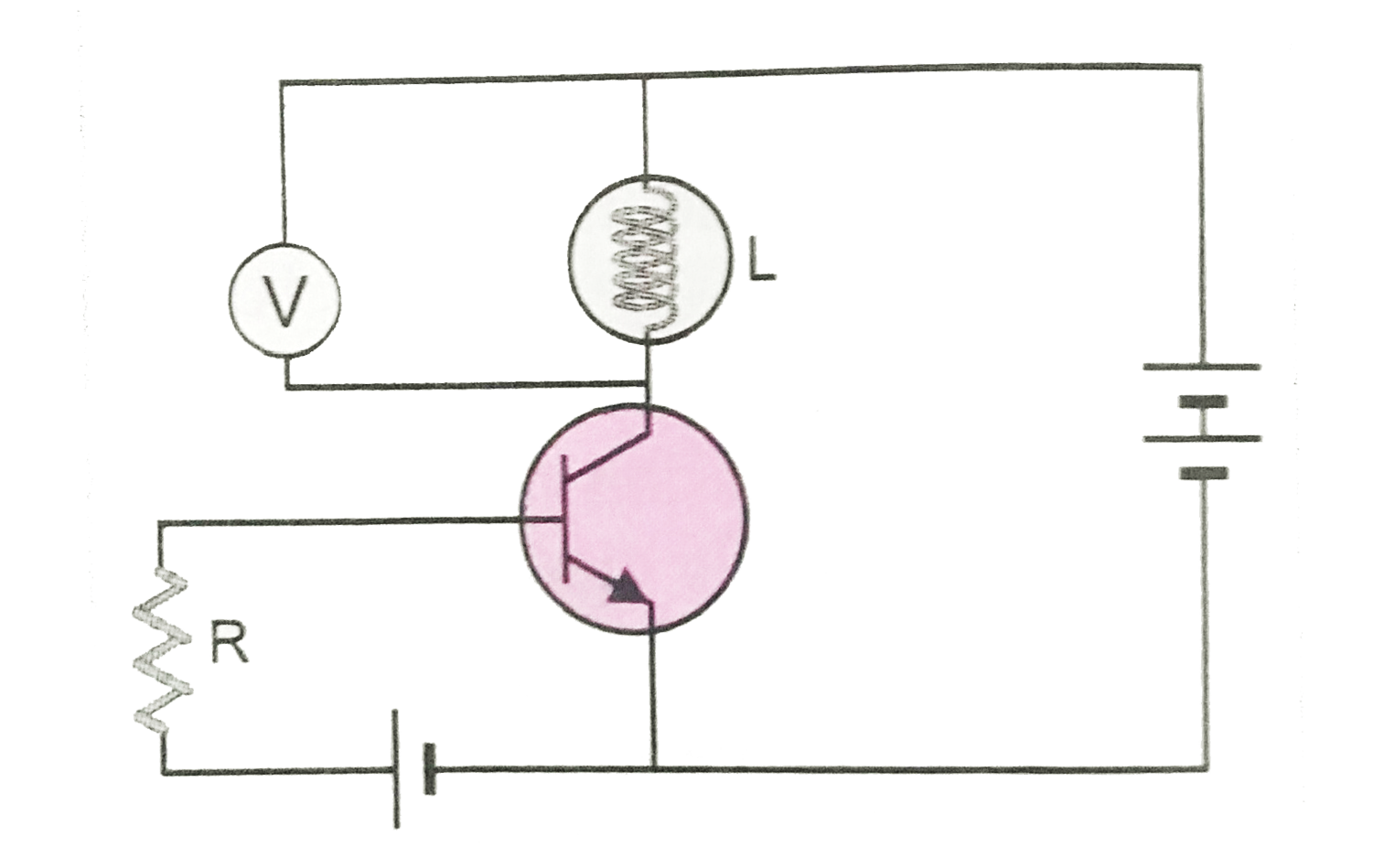
View SolutionIn the circuit shown in figure value of VR is
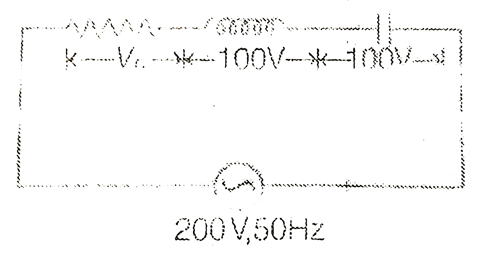
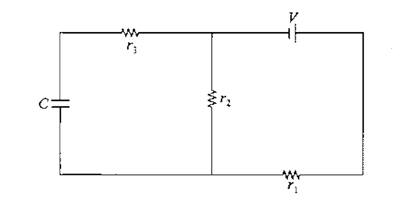
View SolutionIn the circuit shown in figure, the final voltage drop across the capacitor C is :
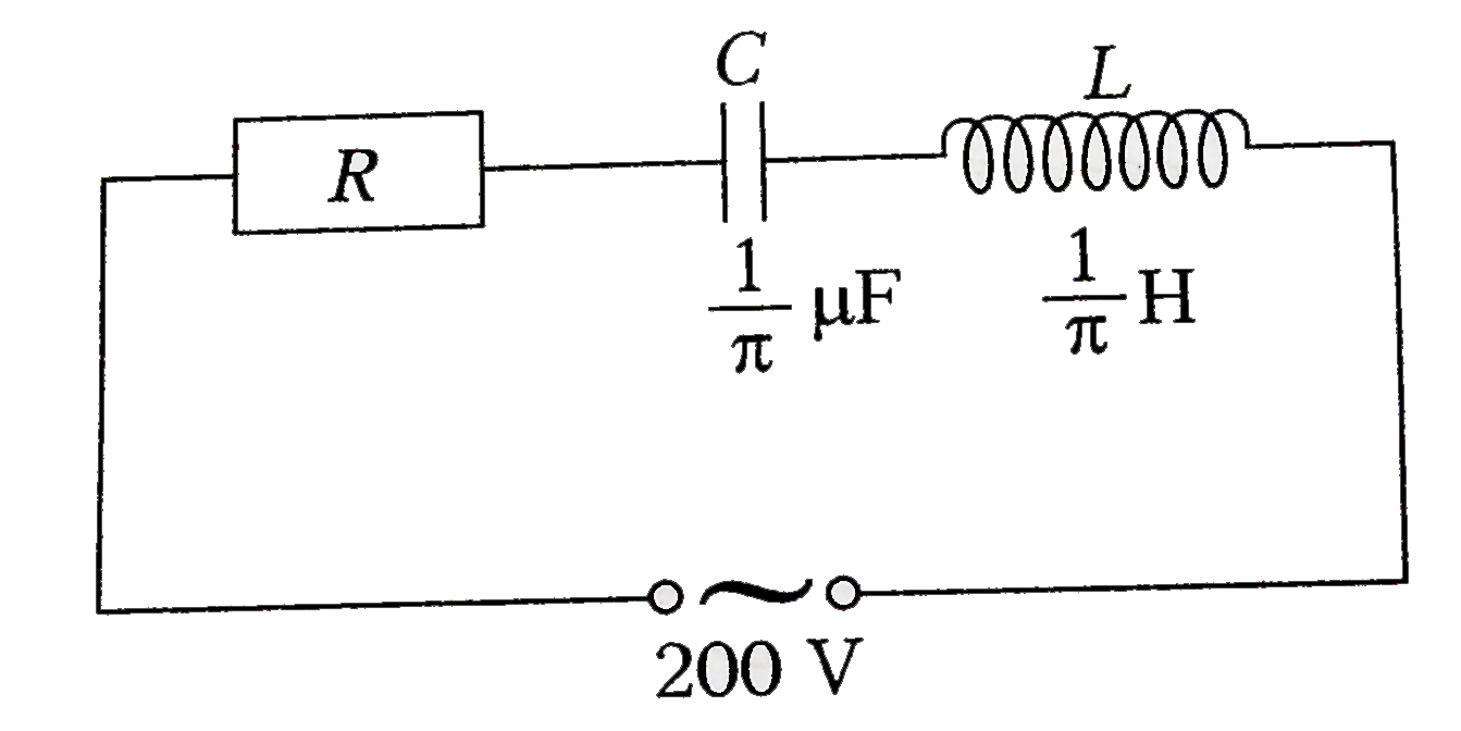
View SolutionIn the circuit shown in figure , the supply has a constant rms value V but variable frequency f. The frequency at which the voltage drop across R is maximum is
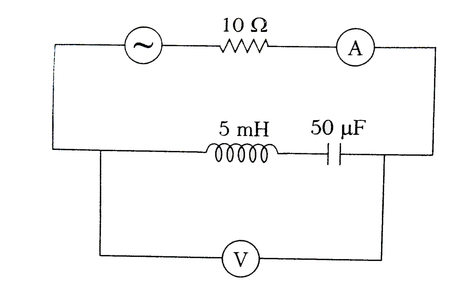
View SolutionIn the circuit shown in figure, the AC source gives a voltage V = 20 cos(2000 t ) . Neglecting source resistance, the voltmeter and ammeter readings will be (approximately)
View Solution
