Fig. illustrates a segment of a double line carrying direct current whose direction in indicated by the arrows. Taking into account that the potential φ2>φ1, and making use of the Poynting vector, establish on which side (left or right) the source of the current is located.
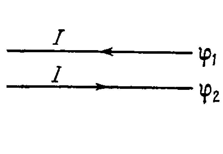
Given φ2>φ1
the electric field is as shown by the dashed lines (……..→…….). The magnetic field is as shown (⊙) emerging out of the paper.
→S=→E×→H is parellel to the wires and towards right.
Hence source must be on the left.

Topper's Solved these Questions
- OSCILLATIONS AND WAVESBOOK - IE IRODOV, LA SENA & SS KROTOVCHAPTER - OSCILLATIONS AND WAVESEXERCISE - Elastic Waves
39 Videos
- OPTICSBOOK - IE IRODOV, LA SENA & SS KROTOVCHAPTER - OPTICSEXERCISE - Exercise
2 Videos
- PHYSICAL FUNDAMENTALS OF MECHANICSBOOK - IE IRODOV, LA SENA & SS KROTOVCHAPTER - PHYSICAL FUNDAMENTALS OF MECHANICSEXERCISE - Relativistic Mechanics
49 Videos
Similar Questions
Two contours are positioned in such a manner that their planes are parallel to each other. Contour 1 carries a current whose direction is designated by an arrow. The contours move in relation to one another, but their planes remain parallel in the process. What is the direction of the current induced in contour 2 when the contours are moved toward each other or away from each other?
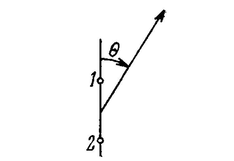
View SolutionA system illustrated in Fig. consists of two coherent point sources 1 and 2 located in a certain plane so that their dipole moments are oriented at right angles to that plane. The sources are separated by a disatnce d, the radiation wavelength is equal to λ. Taking into account that the oscillations of source I by φ(φ<π), find:
(a) the angles θ at which the radiation intensity is maximum,
(b) the conditions under which the radiation intensity in the direction θ=π is maximum and in the opposite direction, minimum.
View Solution
Knowledge Check
A rectangular loop of wire with dimensions shown in figure is coplanar with a long wier carrying current 'I'. The distance between the wire and the left side of the loop is r. The loop is pulled to the right as indicated. What are the directions of the induced current in the loop and the magnetic forces on the left and right sides of the loop when the loop is pulled ?
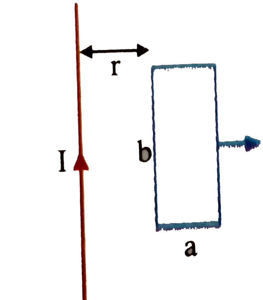 AInduced CurrentForce on Left sideForce on Right sideaCurrentclockwiseTo the leftTo the leftBInduced CurrentForce on Left sideForce on Right sidebCurrentclockwiseTo the rightTo the leftCInduced CurrentForce on Left sideForce on Right sidecClockwiseTo the rightTo the leftDInduced CurrentForce on Left sideForce on Right sidedClockwiseTo the leftTo the right
A current of 10A flows around a closed path in a circuit which is in the horizontal plane as shown in the figure. The circuit consists oi eight alternating arcs of radii r1=0.08m and r2=0.12m. Each subtends the same angle at the centre.
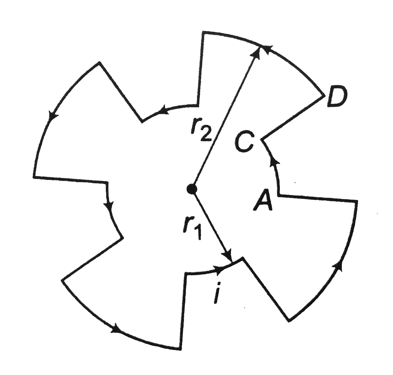
a. Find the magnetic field produced by this circuit at the centre.
b. An infinitely long straight wire carrying as current of 10A is passing through the centre of the above circuit vertically with the direction of the current being into the pane of the circuit. what is the force acting on the wire at the centre due to the current in the circuit? What is the force acting on the arc AC and the straight segment CD due to the current at the centre?
View SolutionA rectangular loop of wire shown below is coplanar with a long wire carrying current I.
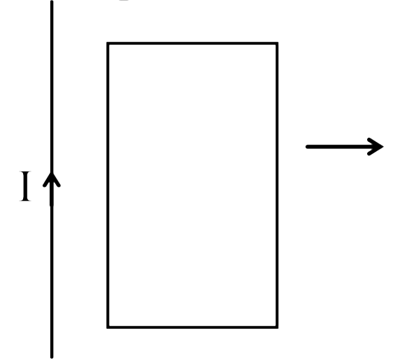 The loop is pulled to the right as indicated. What are the directions of the induced current in the loop and the magnetic forces on the left and the right sides of the loop
View SolutionA rectangular loop of wire with dimensions shown in figure is coplanar with a long wire carrying current 'I'. The distance between the wire and the left side of the loop is r. The loop is pulled to the right as indicated. What are the directions of the induced current in the loop and the magnetic forces on the left and right sides of the loop when the loop is pulled ?

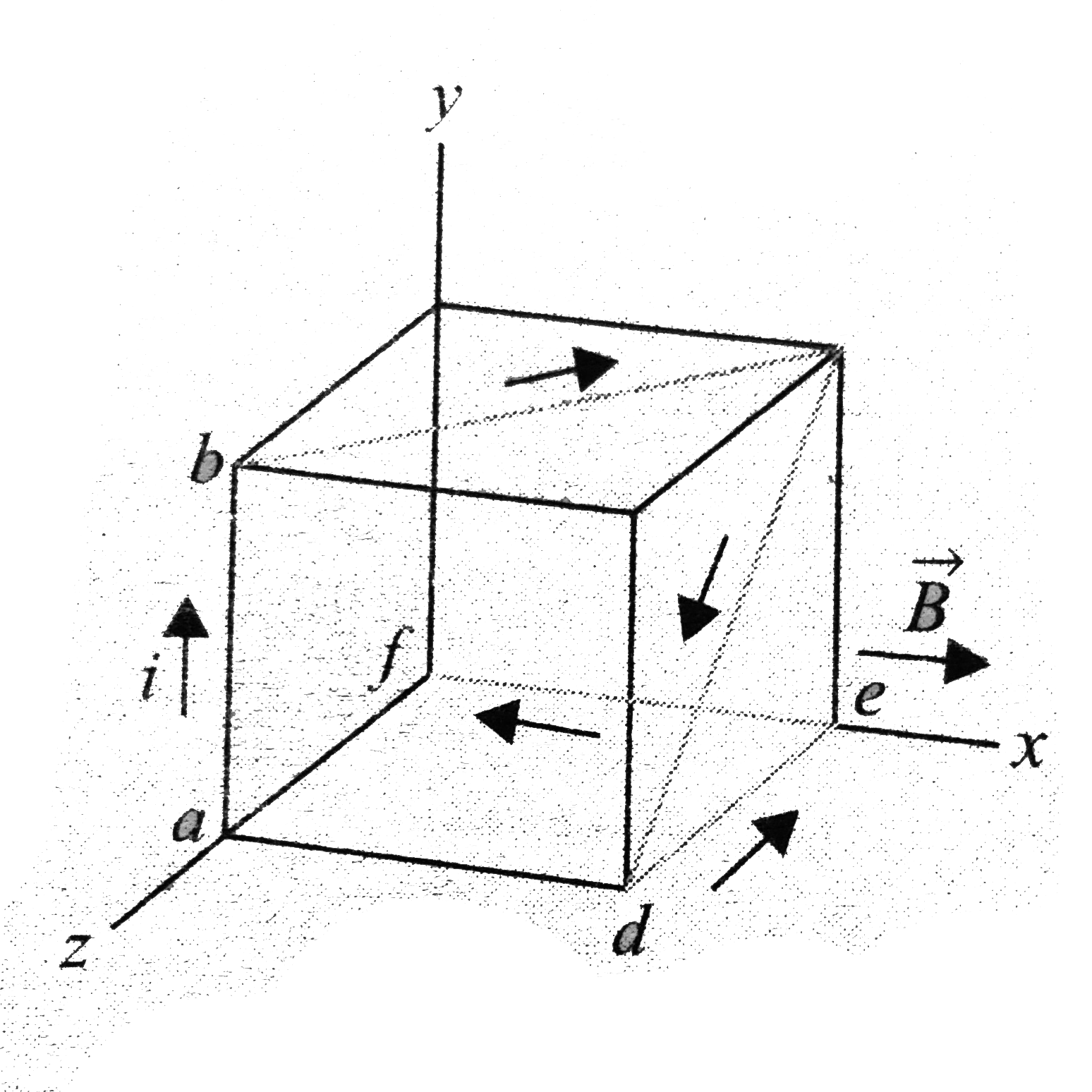
View SolutionThe cube as shown in Fig. 1.61, 75.0 cm on a side, is placed in a uniform magnetic field of 0.860 T parallel to the x-axis. The wire abcdef carries a current of 6.58 A in the direction indicated.
(a) Determine the magnitude and direction of the force acting on the segment ab.
(b) Determine the magnitude and direction of the force acting on the sement bc.
(c) Determine the magnitude and direction of the force acting on the segment cd.
(d) Determine the magnitude and direction of the force acting on the segment de.
(e) Determine the magnitude and direction of the force acting on the segment ef.
(f) What are the magnitude and direction of the total force on the wire ?

View SolutionA wire AB is carrying a steady current of 12 A and is lying on the table. Another wire CD carrying 5 A is held directly above AB at a height of 1mm. Find the mass per unit length of the wire CD so that it remains suspended at its position when left free. Give the direction of the current flowing in CD with respect to that in AB. [Take the value of g=10ms−2]
View SolutionA wire AB is carrying a steady current of 12 A and is lying on the table. Another wire CD carrying 5 A is held directly above AB at a height of 1mm. Find the mass per unit length of the wire CD so that it remains suspended at its position when left free. Give the direction of the current flowing in CD with respect to that in AB. [Take the value of g=10ms−2]
View Solution
