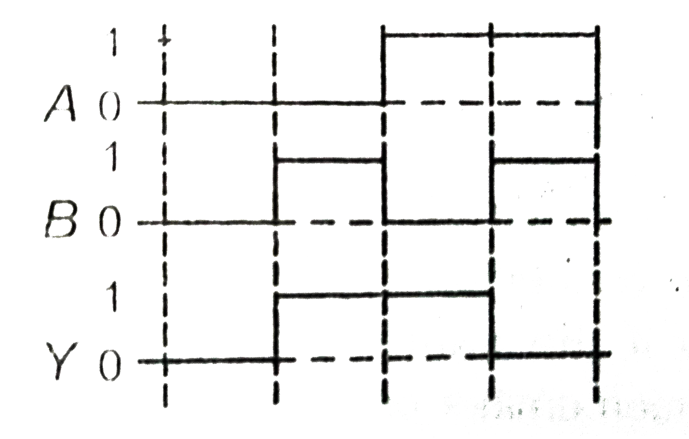
Waveforms of two inputs A and B and output Y are shown in Fig. 2.40. Find Boolean algebraic equation of the associated logic gate and draw the circuit diagram of it.

From the given waveforms, we get the following truth table.
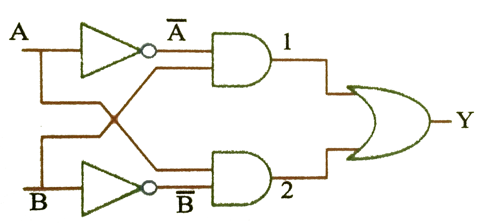
For this truth table, the Boolean algebratic equation of associated gate is Y = A. The circuit diagram of associated logic is shown in Fig. 2.41.

Topper's Solved these Questions
- BOOK - CHHAYA PUBLICATIONCHAPTER - DIGITAL CIRCUITS EXERCISE - NCERT TEXTBOOK QUESTIONS WITH ANSWER HINT2videos
DIGITAL CIRCUITS
- BOOK - CHHAYA PUBLICATIONCHAPTER - DIGITAL CIRCUITS EXERCISE - EXERCISE7videos
DIGITAL CIRCUITS
- BOOK - CHHAYA PUBLICATIONCHAPTER - DIGITAL CIRCUITS EXERCISE - SECTION RELATED QUESTIONS28videos
DIGITAL CIRCUITS
- BOOK - CHHAYA PUBLICATIONCHAPTER - DIFFRACTION AND POLARISATION OF LIGHTEXERCISE - CBSE SCANNER27videos
DIFFRACTION AND POLARISATION OF LIGHT
- BOOK - CHHAYA PUBLICATIONCHAPTER - ELECTRIC ENERGY AND POWEREXERCISE - CBSE SCANNER7videos
ELECTRIC ENERGY AND POWER
Similar Questions
Knowledge Check
- Question 1 - Select One
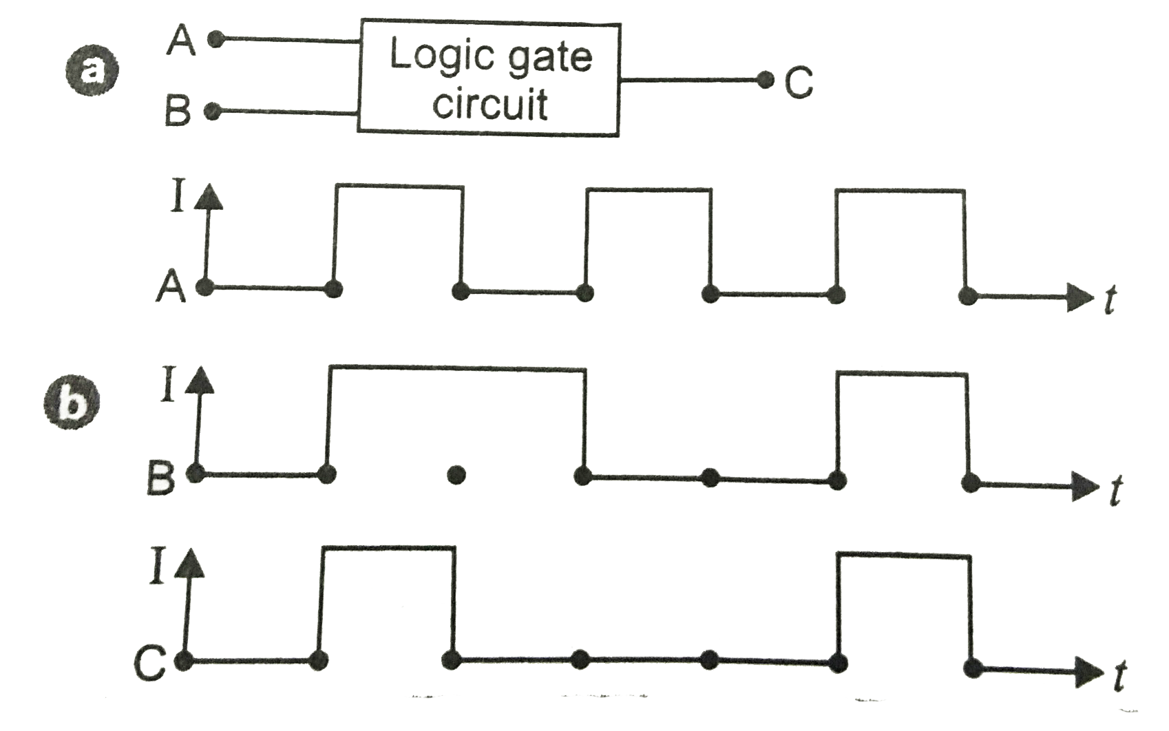
The Fig.shows a logic gate circuit with two inputs A and B and the output C are as shown in Fig.
 AOR gateBAND gateCNAND gateDNOR gate
 - Question 2 - Select One
The Boolean expression of the output y in terms of the input A and B for the circuit shown in figure.
 A¯¯¯AB+A¯¯¯BBABCAB+¯¯¯A¯¯¯BDA¯¯¯B+1
 - Question 3 - Select One
The Boolean expression of the output y in terms of the input A and B for the circuit shown in figure.
 A¯¯¯AB+A¯¯¯BBABCAB+¯¯¯A¯¯¯BDA¯¯¯B+1
Using the wave forms of the input A and B, draw the output waveform of the given logic circuit . Identify the logic gate obtained . Write also the truth table.
 View Solution
Using the wave forms of the input A and B, draw the output waveform of the given logic circuit . Identify the logic gate obtained . Write also the truth table.
 View Solution
There is a gate with two inputs A and B, and one output Y. using the input and output wave forms identify the gate
 View Solution
There is a gate with two inputs A and B, and one output Y. using the input and output wave forms identify the gate
 View Solution
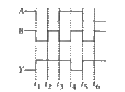
The figure shows the voltage waveforms across two inputs A and B and the output Y of a logic circuit. The logic circuit gate is
 View Solution


 .
.