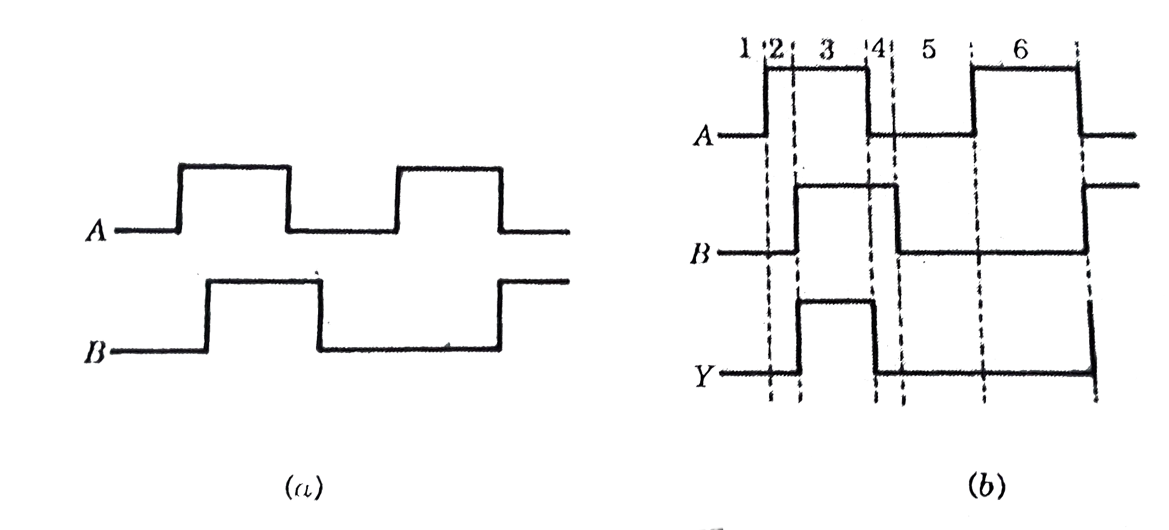
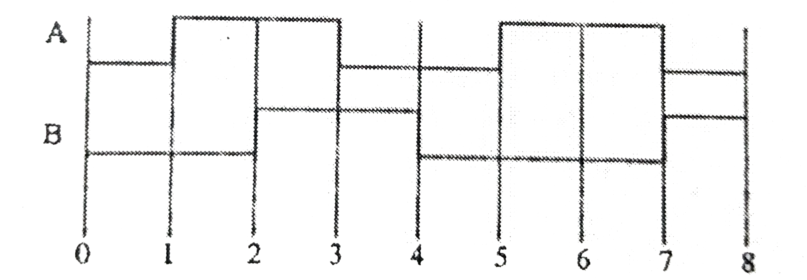
The waveforms of two digital signals A and B are shown in Fig. 2.38 . If we apply these two signals A and B to an OR gate as inputs, then what will be the output waveform?

 In different intervals of time, possible combinations of values 0 or 1 of A and B are shown in truth table. From truth table, waveform of the output Y is shown in Fig. 2.39.
Topper's Solved these Questions
- DIGITAL CIRCUITS BOOK - CHHAYA PUBLICATIONCHAPTER - DIGITAL CIRCUITS EXERCISE - NCERT TEXTBOOK QUESTIONS WITH ANSWER HINT
2 Videos
- DIGITAL CIRCUITS BOOK - CHHAYA PUBLICATIONCHAPTER - DIGITAL CIRCUITS EXERCISE - EXERCISE
7 Videos
- DIGITAL CIRCUITS BOOK - CHHAYA PUBLICATIONCHAPTER - DIGITAL CIRCUITS EXERCISE - SECTION RELATED QUESTIONS
28 Videos
- DIFFRACTION AND POLARISATION OF LIGHTBOOK - CHHAYA PUBLICATIONCHAPTER - DIFFRACTION AND POLARISATION OF LIGHTEXERCISE - CBSE SCANNER
27 Videos
- ELECTRIC ENERGY AND POWERBOOK - CHHAYA PUBLICATIONCHAPTER - ELECTRIC ENERGY AND POWEREXERCISE - CBSE SCANNER
7 Videos
Similar Questions
Knowledge Check

input are given as shown
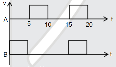
then output signal is-A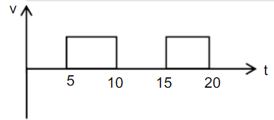 B
B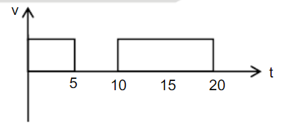 C
C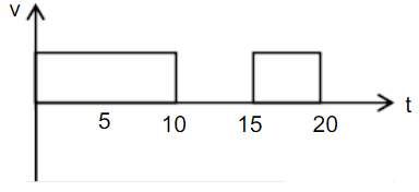 D
D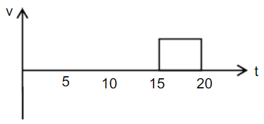
The real time variation of input signals A and B are as shown below. If the inputs are fed into NAND gate, then select the output signal from the following :-
_E01_434_Q01.png) A
A_E01_434_O01.png) B
B_E01_434_O02.png) C
C_E01_434_O03.png) D
D_E01_434_O04.png)
The real time variation of input signals A and B are as shown below. If the inputs are fed into NAND gate, then select the output signal from the following :-
_E01_434_Q01.png) A
A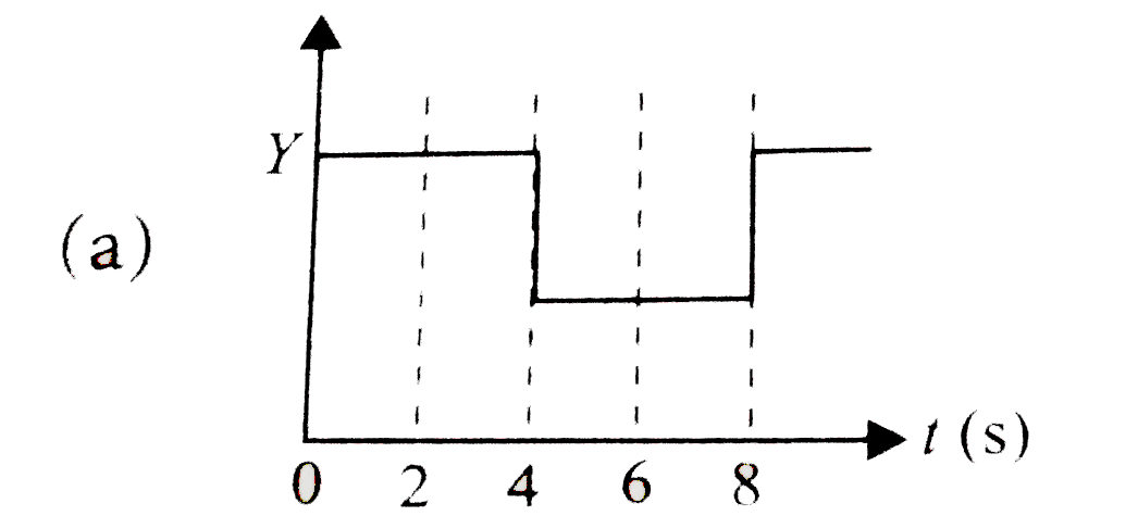 B
B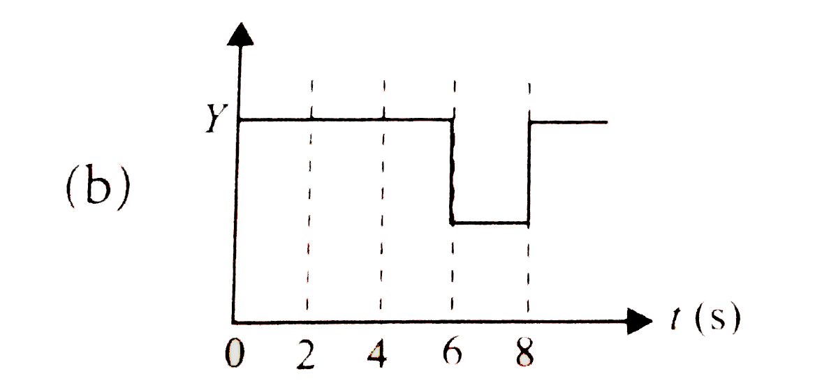 C
C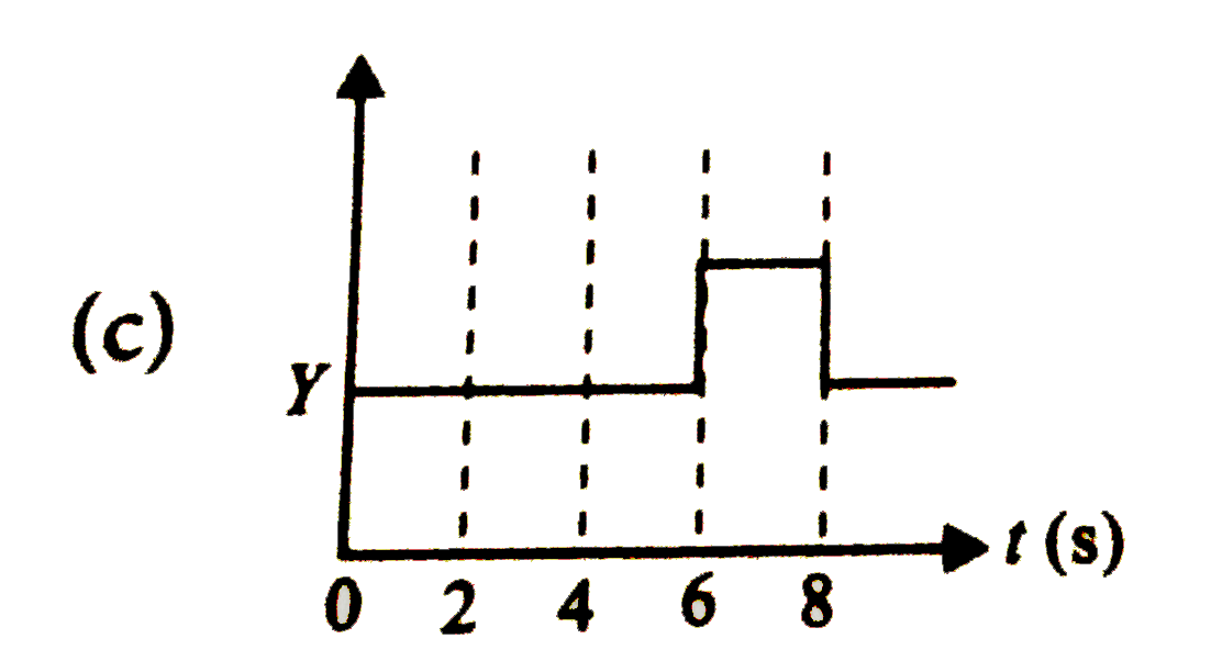 D
D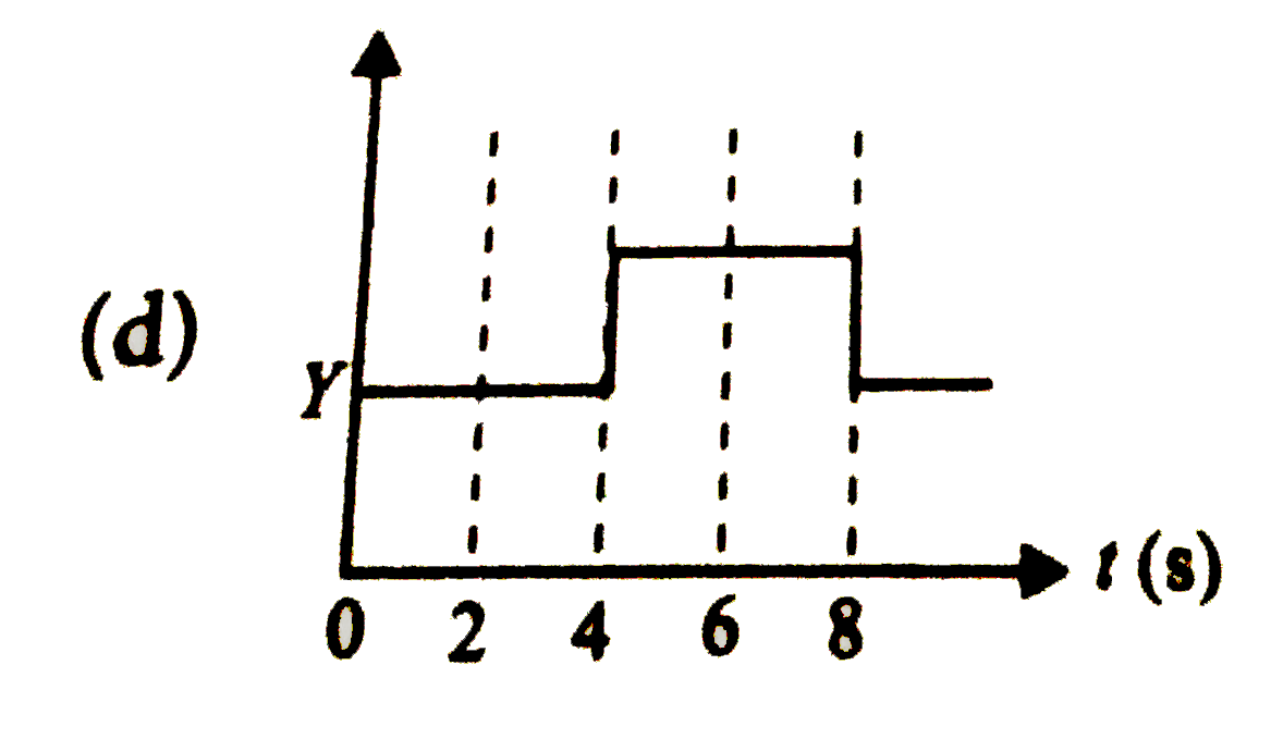
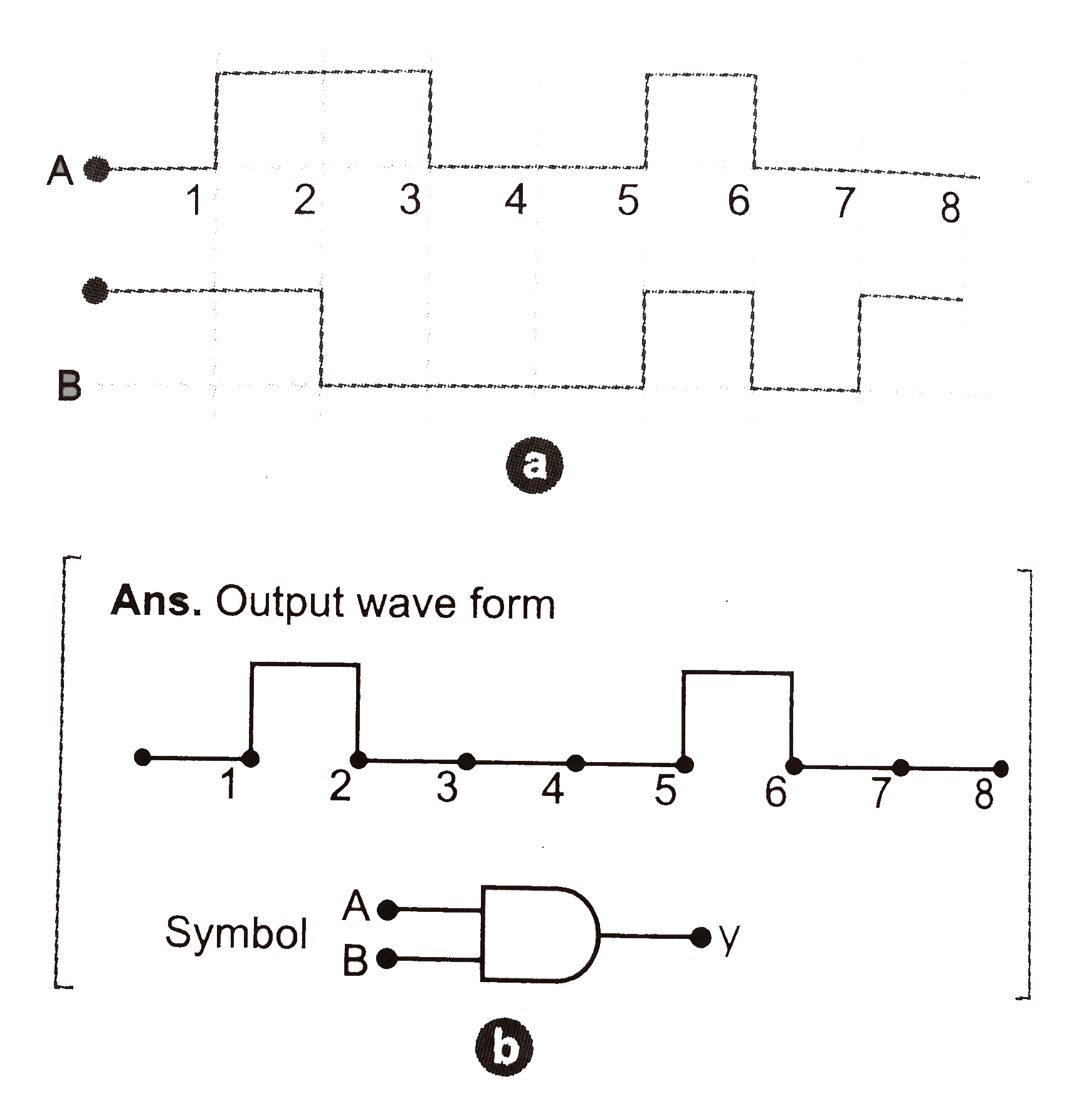
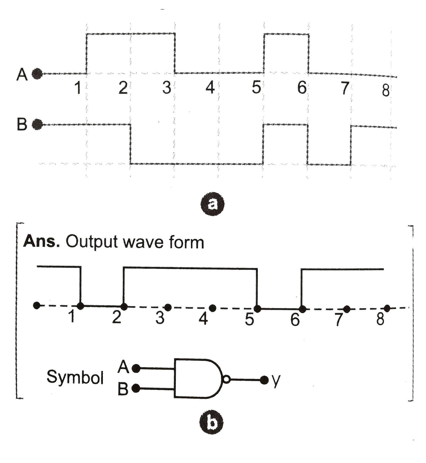
Two signal A and B shown in the Fig. are used as two inputs of a NAND gate. Draw its output wave form. Give the logic symbol of NAND gate.
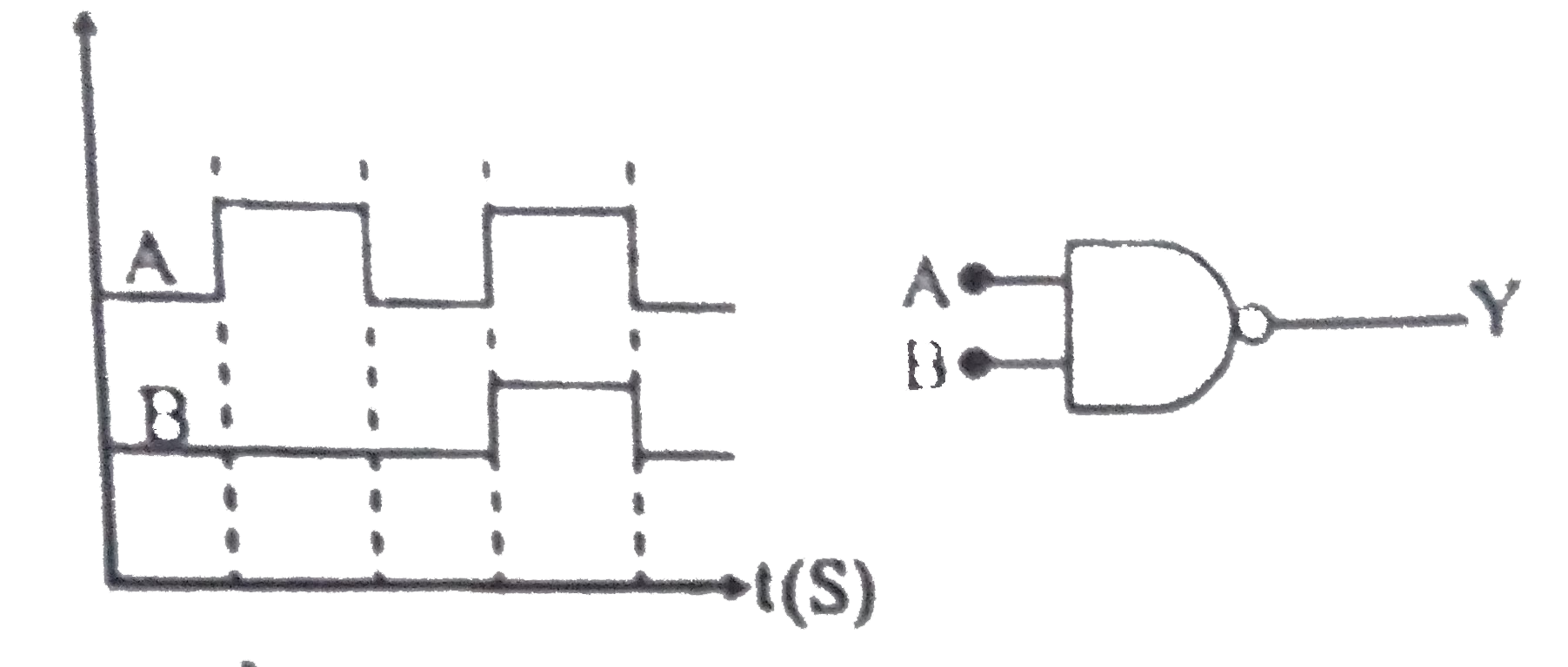
View Solution(i) Sketch the output waveform from an AND gate for the inputs A and B shown in the figure.
(ii) If the output of the above AND gate is fed to a NOT gate, name the gate of the combination so formed.
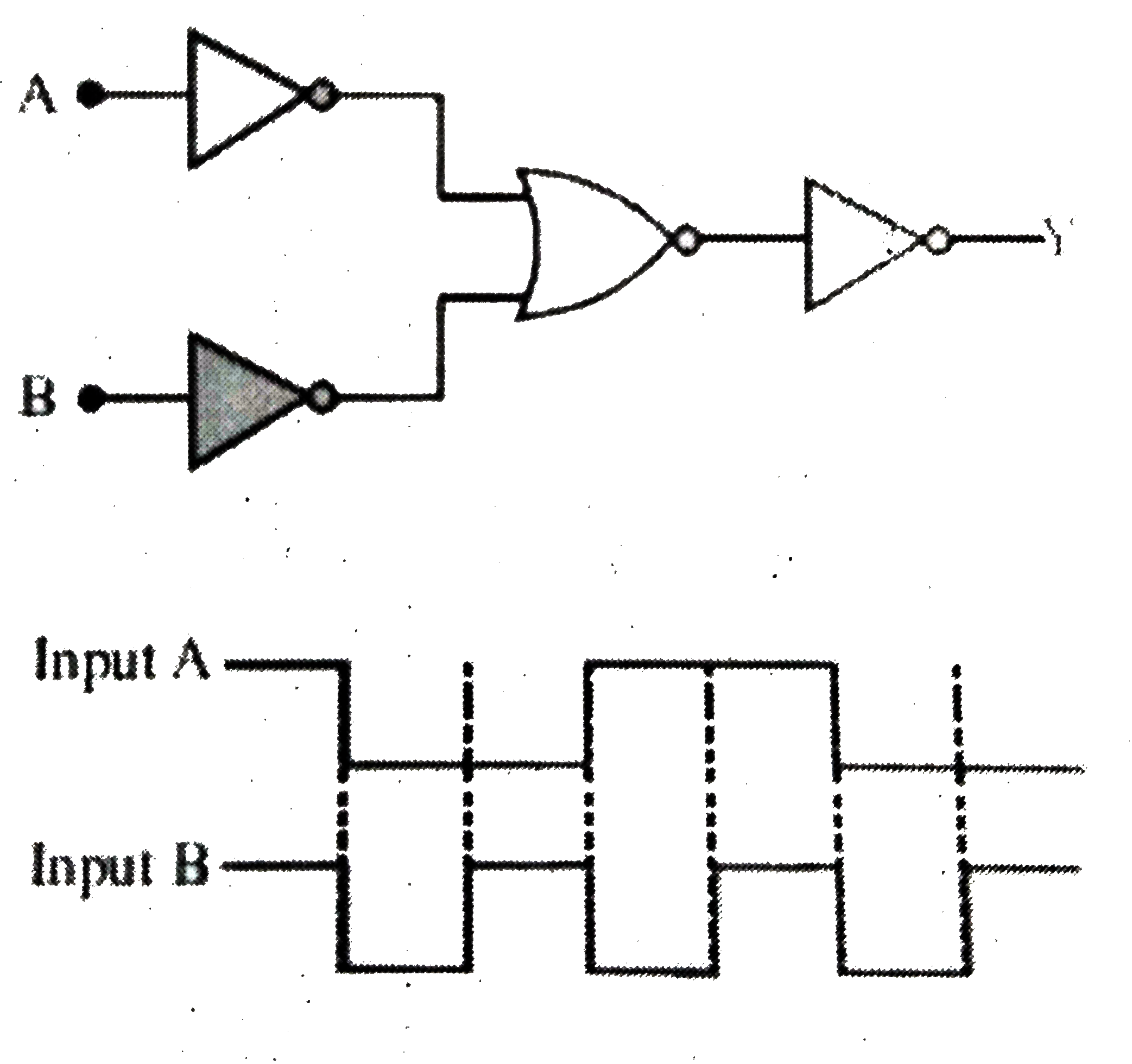
View SolutionThe logic circuit shown has the input waveforms 'A' and 'B' as shown. Pick out the correct output waveform
View SolutionThe real time variation of input signals A & B are as shown below. If the inputs are into NAND gate, then select the output signals from the following-
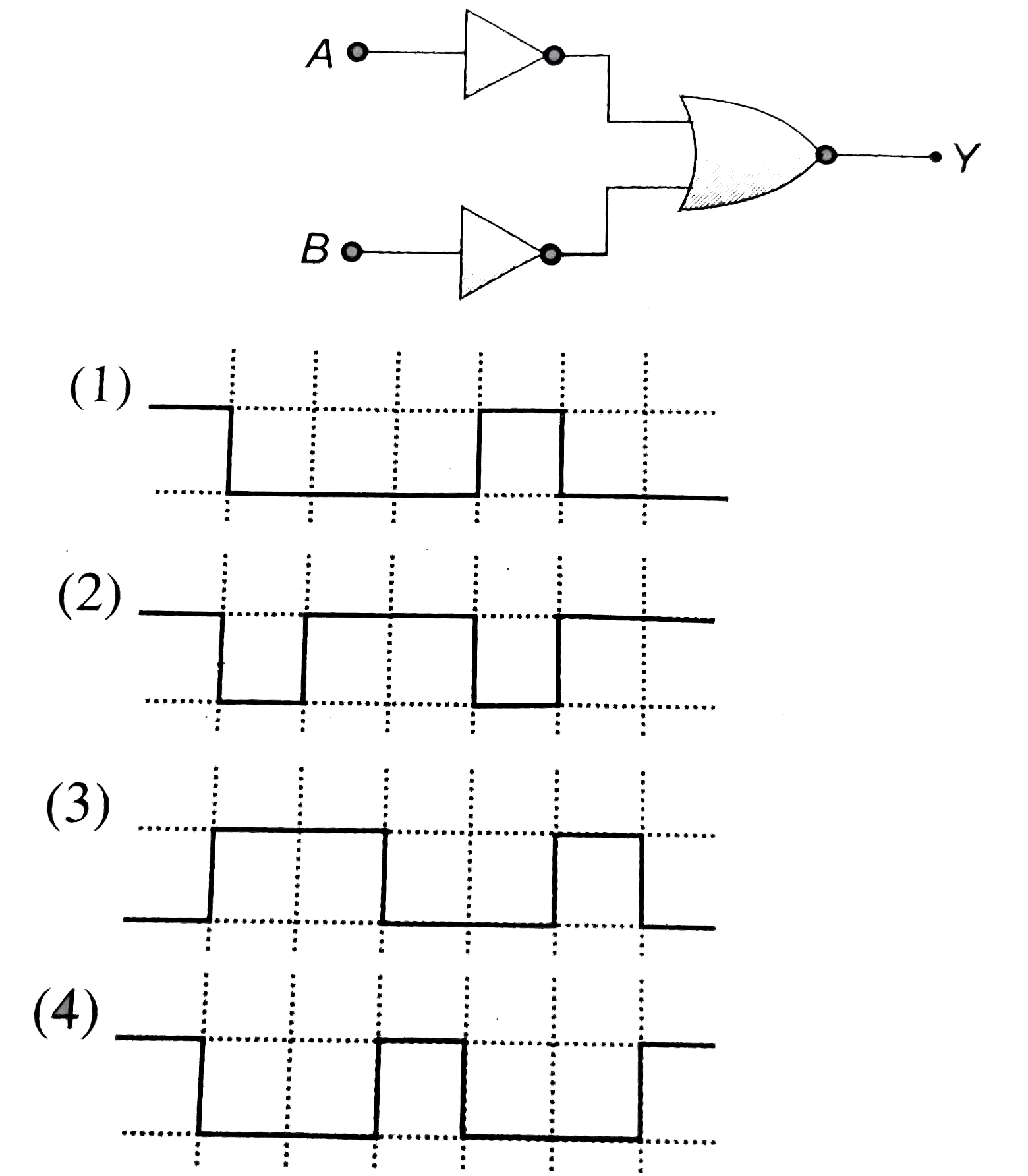
View SolutionThe logic circuit shown belows has the input waveforms 'A' and 'B' as shown. Pick out the correct output waveform
View Solution

