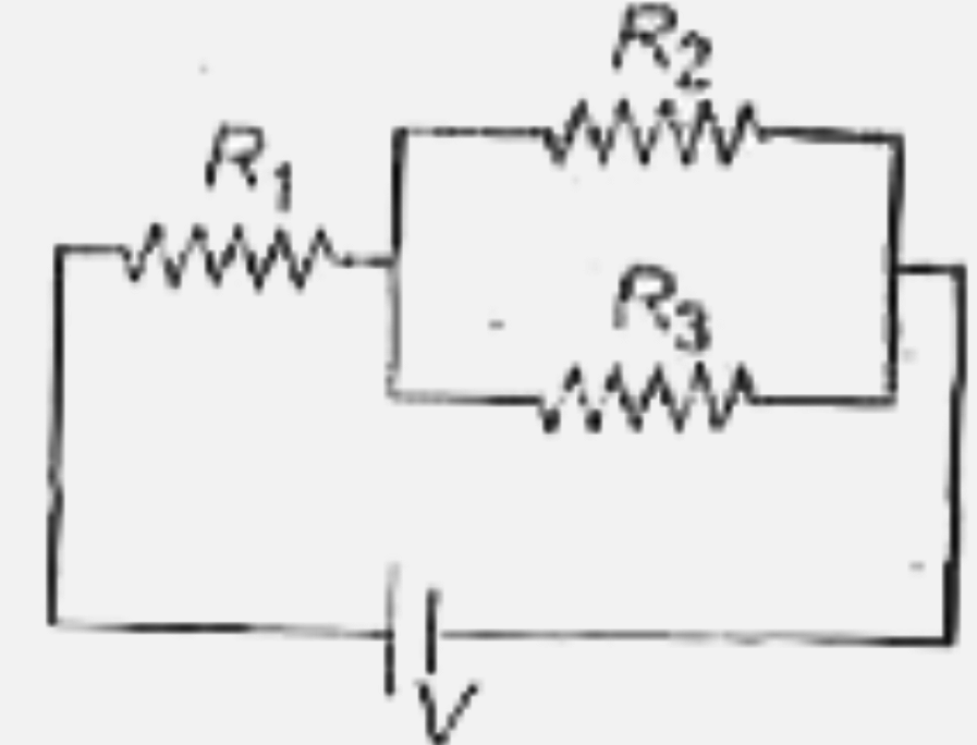
For ensuring dissipation of same energy in all three resistors (R1,R2,R3) connected as shown in figure, their values must be related s

R1=R2=R3
R2=R3 and R1=4R1
R2=R3 and R1=R2/4
R1=R2+R3
The correct Answer is:C
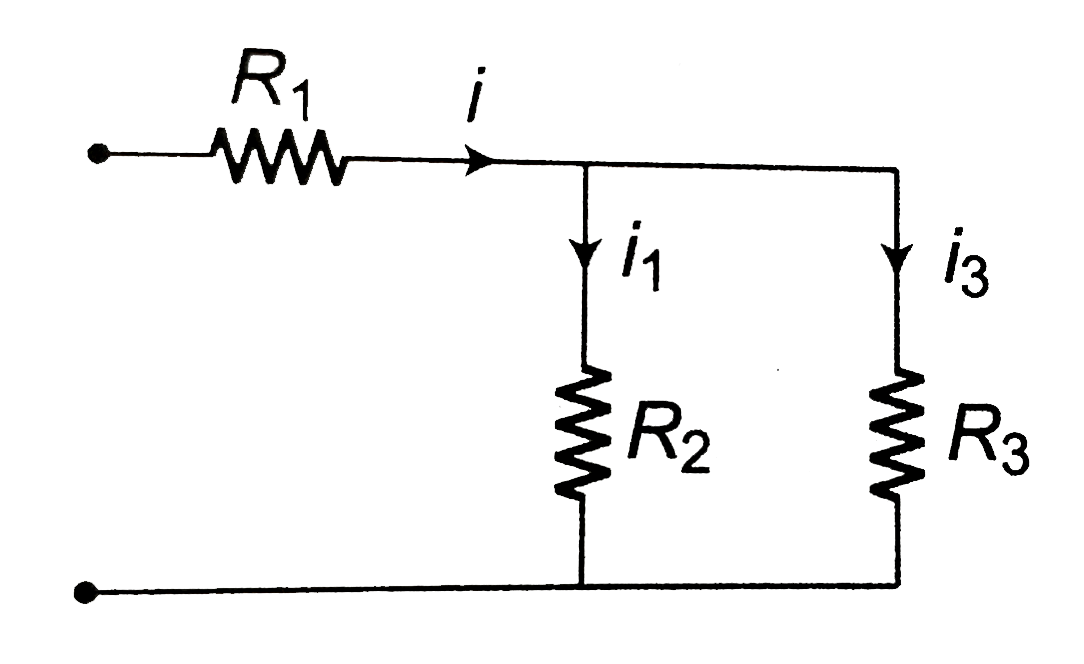
i1=(R3R2+R3)i,i2=(R2R2+R3)i
P1=P2=P3
i2R2=i22R3
i2R1=i21R2=i22R3
i2R1=(R3R2+R3)2i2R2=(R3R2+R3)2R3
R1=(R3R2+R3)2R2=(R3R2+R3)2R3
(R3R2+R3)2R2+(R3R2+R3)2R3⇒R23R2=R22R3 Mbrlt R3=R2
R1=(R3R2+R3)2R2=(R3R2+R3)2R2=R24.
Topper's Solved these Questions
- THERMAL AND ELECTRIC EFFECT oF CURRENTBOOK - CP SINGHCHAPTER - THERMAL AND ELECTRIC EFFECT oF CURRENTEXERCISE - Exercises
101 Videos
- SEMICONDUCTORSBOOK - CP SINGHCHAPTER - SEMICONDUCTORSEXERCISE - Exercises
140 Videos
- WAVE NATURE OF LIGHTBOOK - CP SINGHCHAPTER - WAVE NATURE OF LIGHTEXERCISE - EXERCISES
140 Videos
Similar Questions
Knowledge Check
For ensuring disspation of same energy in all three resistors (R1,R2,R3) connected as shown in figure, their values must be related as –
 AR1=R2=R3BR2=R3andR1=4R2CR2=R3andR1=14R2DR1=R2+R3
Two ideal batteries of emf V1andV2 and three resistances R1,R2andR3 are connected as shown in the figure. The current in resistance R2 would be zero if
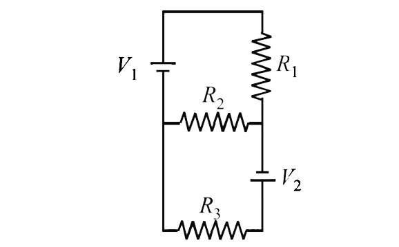 AV1=V2andR1=R2=R3BV1=V2andR1=2R2=R3CV1=2V2and2R1=2R2=R3D2V1=V2and3R1=R2=R3
Three equal resistors, each equals to r are connected as shown in figure. Then, the equivalent resistance between points A and B is
ArB3rCr3D2r3
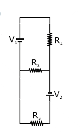
Two ideal batteries of emf V1andV2 and these resistances R1,R2andR3 are connected as shown in the figure . The current in resistance R2 would be zero if
View SolutionIf resistors of resistance R1 and R2 are connected in parallel,then resultant resistance is "
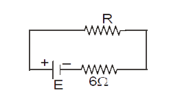
View SolutionA resistor R is connected to a cell as shown in the figure. The value of R for which in its is maximum is:-
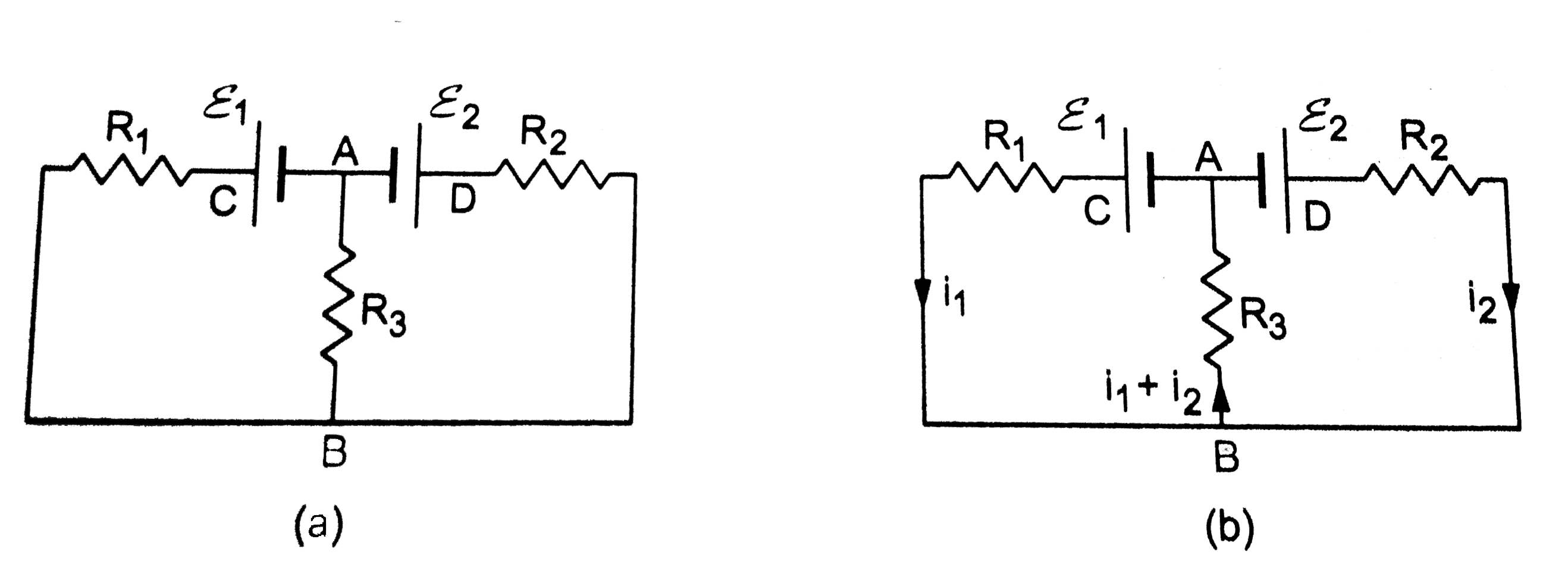
View SolutionFind the currents going through the three resistors R_(v),R_(2)andR_(3) in the circuit of figure.
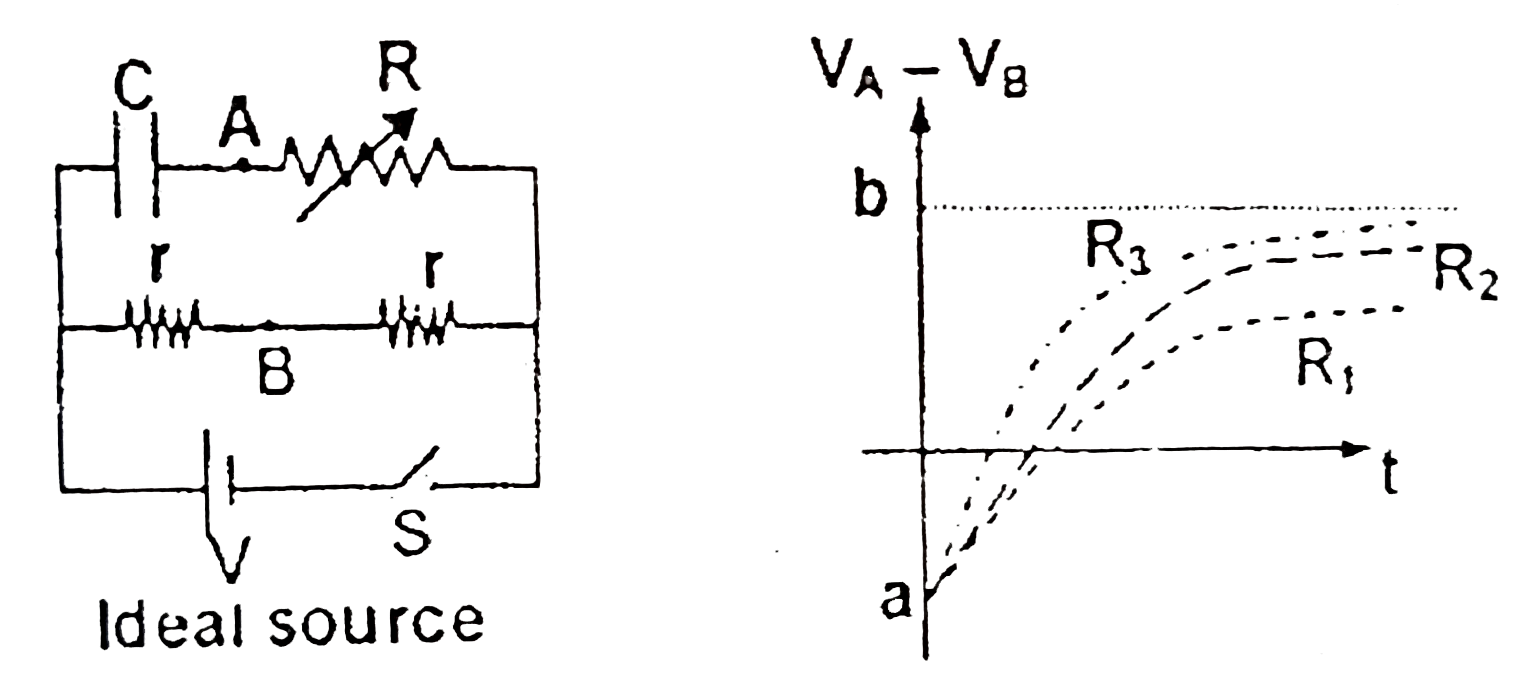
View SolutionAn uncharged capacitor C and a variable resistance R are connected to an ideal source and two resistors with the help of a switch at t=0 as shown in the figure. Initially capacitor is uncharged and switch S is closed at t=0sec. The graph between VA−VB for variable Resistor R for its three different values R1, R2, and R3 versus time is shown in the figure II. Choose the correct statement
View Solution

