A circular conducting loop of radius R and resistance per unit length λ is pulled out from the regio of uniform magnetic filed with constant velocity v. The situation shown in the figure corresponds to that is at t=0. Mark out the correct statement (s)

Just after t=0i.e., the motion starts, the induced current in the loop is √3Bv2πλ
Current will be induced in the loop for 3R2v sec.
At any time t, the current induced in the loop is given by Bv√3R2−4v2t2+4Rvtλ×2πR and is in clockwise direction.
Induced current is in clockwise direction for t=0 to R2v and thereafter it becomes in anticlockwise direction.
The correct Answer is:A,B,C,D
At any time t, the situation would be as shown in the figure below :

PO=√R2−(R2−vt)2
Emf induced e=Bv×2PO
i=eλ×2πR
As flux is decrasing with time, induced emf will try to oppose the decreasing flux and hence induced current would be in clockwise direction.
Topper's Solved these Questions
- MOVING CHARGES AND MAGNETISMBook:NARAYNAChapter:MOVING CHARGES AND MAGNETISMExercise:Level =I (H.W)
Explore 42 Videos
- MOVING CHARGES AND MAGNETISMBook:NARAYNAChapter:MOVING CHARGES AND MAGNETISMExercise:Level -II (H.W)
Explore 37 Videos
- MOVING CHARGES AND MAGNETISMBook:NARAYNAChapter:MOVING CHARGES AND MAGNETISMExercise:LEVEL-V (SINGLE ANSWER QUESTION)
Explore 85 Videos
- MAGNETISM AND MATTERBook:NARAYNAChapter:MAGNETISM AND MATTERExercise:EXERCISE - 4 (SINGLE ANSWER TYPE QUESTION)
Explore 17 Videos
- NUCLEAR PHYSICSBook:NARAYNAChapter:NUCLEAR PHYSICSExercise:LEVEL-II-(H.W)
Explore 9 Videos
Similar Questions
Knowledge Check
For the situation shown in the figure below (assume r>> length fo dispole ) mark out the correct statement (s) -
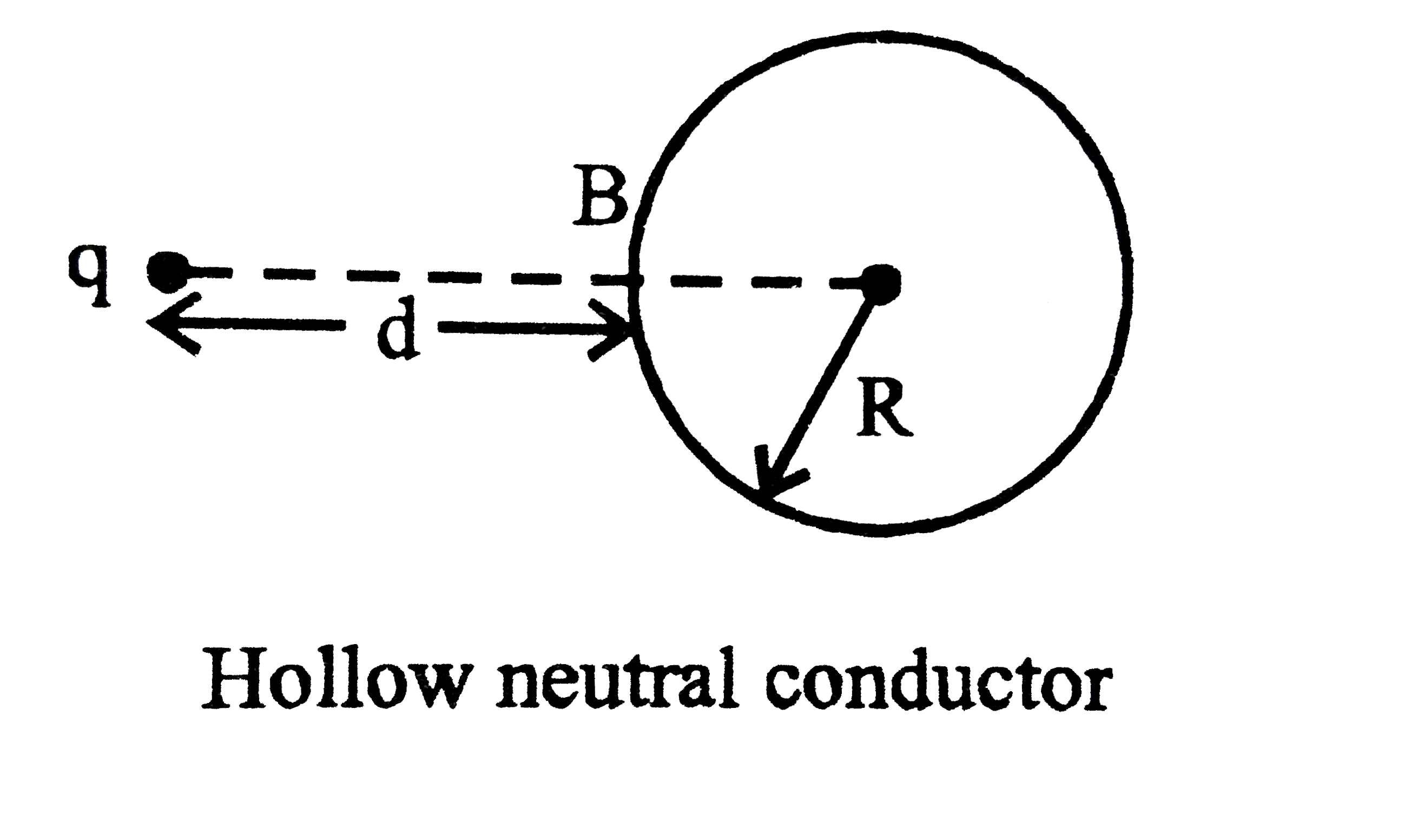 .APotential of the conductor is q4πɛ0(d+R)BPotential of the conductor is q4πɛ0dCPotential of the conductor can't be determined as nature of distribution of induced charges is not knownDPotential at point B due to induced charges is −1R4πɛ0(d+R)d
For the situation shown in the figure below ("assume "r>> length fo dispole ) mark out the correct statement (s) -
 .AForce acting on the dipole is zeroBForce acting on the dipole is approximately PQ4πe0r2 and is acting upwardCTorque acting on the dipole is pq4πe0r2 clockwise directionDTorque acting on the dipole is pQ4πe0r2 in ant i-clockwise direction
A circular conducting loop of radius r0 and having resistance per unit length λ as shown in the figure is placed in a magnetic field B which is constant in space and time. The ends of the loop are crossed and pulled in opposite directions with a velocity v such that the loop always remains circular and the radius of the loop goes on decreasing, then
 Aradius of the loop changes with r as r=r0−vtπBemf induced in the loop as a function of time is ε=2Bv[r0−vtπ]Ccurrent induced in the loop is I=Bv2πλDcurrent induced in the loop is I=Bvπλ.
For the situation shown in the figure below mark out the correct statement (s) -
 .
.
View SolutionFor the situation shown in the figure below, mark out the correct statement(s) :
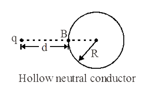
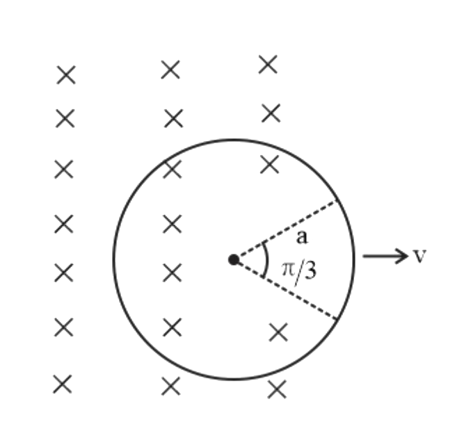
View SolutionA uniform circular loop of radius a and resistance R is pulled at a constant velocity v out of a region of a uniform plane of the loop and the velocity are both perpendicular to B. Then the electrical power in the circular loop at the instant when the arc (of the circular loop) outside the region of magnetic field subtends an angle π3 at the centre of the loop is
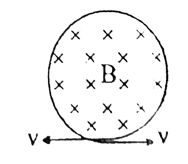
View SolutionA circular conducting loop of radius r0 and having resistance per unit length lamba as shown in the figure is placed in a magnetic field B which is constant in space and time. The ends of the loop are crossed and pulled in opposite directions with a velocity v such that the loop always remains circular and the radius of the loop goes on decreasing then
View SolutionA rectangular loop of resistance R, and sides l and X, is pulled out of a uniform magnetic field B with a for maintaining uniform velocity of withdrawal is __
View Solution
