The potential difference between the ends of a resistance R is VR, between the ends of capacitor is VC=2VR and between the ends of inductance is VL=3VR. Then the alternating potential of the source in terms of VR will be
√2VR
VR
VR√2
5VR
The correct Answer is:1
To find the alternating potential of the source in terms of VR, we need to analyze the potential differences across the resistor, capacitor, and inductor, taking into account their phase relationships.
1. Identify the given potentials:
- The potential difference across the resistor is given as:
VR
- The potential difference across the capacitor is:
VC=2VR
- The potential difference across the inductor is:
VL=3VR
2. Understand the phase relationships:
- The potential across the inductor VL leads the current by 90∘.
- The potential across the capacitor VC lags the current by 90∘.
3. Express the potentials in phasor form:
- We can represent the potentials as phasors:
- For the resistor: VR (in phase)
- For the capacitor: VC=2VR (lagging by 90∘)
- For the inductor: VL=3VR (leading by 90∘)
4. Set up the phasor diagram:
- The phasor for VR is along the horizontal axis.
- The phasor for VC points downwards (negative imaginary axis).
- The phasor for VL points upwards (positive imaginary axis).
5. Calculate the net potential:
- The net potential V from the source can be calculated using the vector sum of the potentials:
V=VR+VL−VC
- Substituting the values:
V=VR+3VR−2VR=2VR
6. Final result:
- Therefore, the alternating potential of the source in terms of VR is:
V=2VR
- The potential difference across the resistor is given as:
VR
- The potential difference across the capacitor is:
VC=2VR
- The potential difference across the inductor is:
VL=3VR
- The potential across the inductor VL leads the current by 90∘.
- The potential across the capacitor VC lags the current by 90∘.
- We can represent the potentials as phasors:
- For the resistor: VR (in phase)
- For the capacitor: VC=2VR (lagging by 90∘)
- For the inductor: VL=3VR (leading by 90∘)
- The phasor for VR is along the horizontal axis.
- The phasor for VC points downwards (negative imaginary axis).
- The phasor for VL points upwards (positive imaginary axis).
- The net potential V from the source can be calculated using the vector sum of the potentials:
V=VR+VL−VC
- Substituting the values:
V=VR+3VR−2VR=2VR
- Therefore, the alternating potential of the source in terms of VR is:
V=2VR
Topper's Solved these Questions
- ALTERNATING CURRENTBOOK - NARAYNACHAPTER - ALTERNATING CURRENTEXERCISE - LEVEL - III (C.W)
24 Videos
- ALTERNATING CURRENTBOOK - NARAYNACHAPTER - ALTERNATING CURRENTEXERCISE - NCERT Based Question
1 Videos
- ALTERNATING CURRENTBOOK - NARAYNACHAPTER - ALTERNATING CURRENTEXERCISE - LEVEL - I (C.W)
23 Videos
- ATOMIC PHYSICSBOOK - NARAYNACHAPTER - ATOMIC PHYSICSEXERCISE - LEVEL-II (H.W)
14 Videos
Similar Questions
Knowledge Check
In an L-C-R series circuit, the potential difference between the terminals of the inductance is 60 V, between the terminals of the capacitor is 30 V and that across the resistance is 40 V. Then, the supply voltage will be equal to
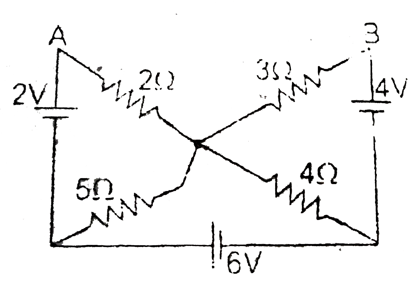
A10 VB50 VC70 VD130 VThe potential difference (VA−VB) between the point A and B in the given figure is
 A+6VB+9VC−3VD+3V
The potential difference (VA−VB) between the point A and B in the given figure is :
 A+6VB+9VC−3VD−8V
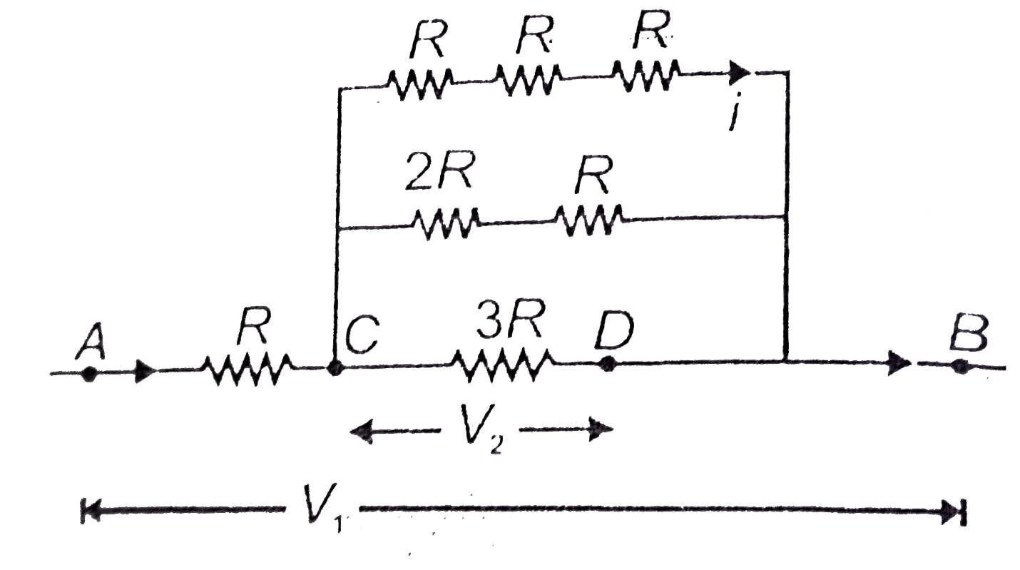
In the circuit shown, the potential differences, V1 ( between A and B ) and V2 ( between C and D ), are

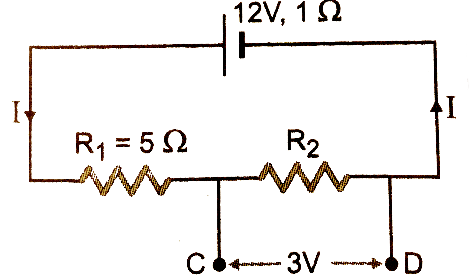
View SolutionIf the circuit a potential difference of 3V is required between the point CandD. Find the value of resistance r2

View SolutionPotential difference between points A and B (i.e. VA−VB) is -----

View SolutionIf V is the potential difference between the ends of conductor and l is the current through it, then ohm's law states that
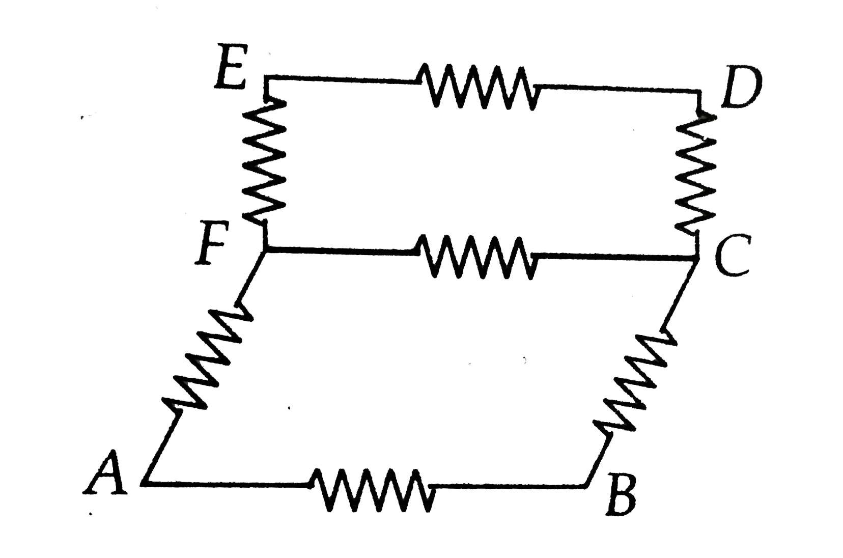
View SolutionIf the potential difference between A and D is V, what will be potential difference between F and C. each of the resistance is R.

View Solution


