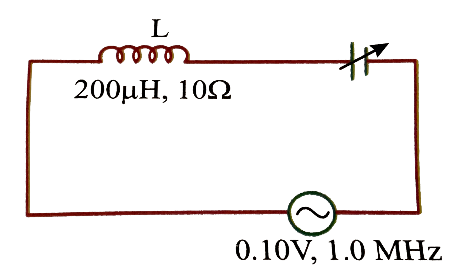
At resonance, VL and VC both very much greater than the applied potential, V itself. The quantity factor for an LCR circuit in resonance is given by Q=XLR. In pratice, Q=200 has been achieved.

At resonance, the capacitor has been adjusted for
(1). 200×10−6μF
(2) 0.00013μF
(3). 0.0012μF
(4). 0.0013F
At resonance, the potential difference across the inductance is
(1) 1.3V
(2) 13V
(3). 0.3V
(d) none of these
The potential across the capacitor at resosnance is
(1) 1.3V
(2) 13V
(3) <13V
(4) none of these
The Q factor is
(1) VLVC
(2) VCVL
(3) VCV
(d) VLV
(e) choose the right statement.
(1) VL+VC can be greater than Vapplied
(2) VL+VC=Vapplied
(3) VL+VC<Vapplied
(4) none of these
The correct Answer is:2, 3, 1, (3,4)
Topper's Solved these Questions
- ALTERNATING CURRENTBOOK - NARAYNACHAPTER - ALTERNATING CURRENTEXERCISE - LEVEL - IV NCERT Based Questions
15 Videos
- ALTERNATING CURRENTBOOK - NARAYNACHAPTER - ALTERNATING CURRENTEXERCISE - LEVEL - V
83 Videos
- ALTERNATING CURRENTBOOK - NARAYNACHAPTER - ALTERNATING CURRENTEXERCISE - LEVEL - III (C.W)
24 Videos
- ATOMIC PHYSICSBOOK - NARAYNACHAPTER - ATOMIC PHYSICSEXERCISE - LEVEL-II (H.W)
14 Videos
Similar Questions
In the given circuit , the potential difference between A and B is 18 V and charge on 2 μF capacitor is 24 μ C . The value of C is

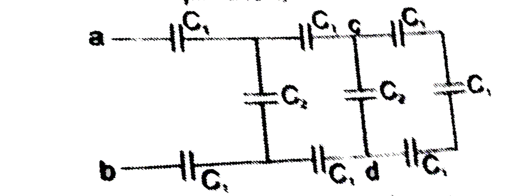
View SolutionIn the arrangement of the capacitor shown in the figure, each C1 capacitor has capacitance of 3μF and each C2 capacitor has capacitance of 2μF then,

(iii) If Vab=900V, then potential difference across points c and d is :
View Solution
Knowledge Check
An alternating e.m.f. of 0.1 V is applied across an LCR series circuit having R=2Ω,C=40μFandL=100mH. At resonance, the voltage drop across the inductor is
A10 VB5 VC2.5 VD20 VFour capacitors 4μF,6μF,5μF,3μF are connected in series to a source of 150V. The potential difference in volt, the 5μF capacitor will be
A30voltB40voltC50 voltD60 voltIn the arrangement of the capacitor shown in the figure, each C1 capacitor has capacitance of 3μF and each C2 capacitor has capacitance of 2μF then,

(iii) If Vab=900V, then potential difference across points c and d is :A60 VB100 VC120 VD200 V
Obtain the resonant frequency and Q factor of a series LCR circuit with L = 3.0 H, C=27μF and R = 7.4 ohm.
View SolutionIn a series resonant LCR circuit the voltage across R is 100 volts and R = 1k(Ω)withC=2(μ)F. The resonant frequency (ω) is 200rad/s. At resonance the voltage across L is
View SolutionIn Fig.25-25 a potentila difference V=100V is applied across a capacitor arragnement with capacitances C1=10.0μF,C2=5.00μFandC3=2.00μF What are (a) charge q3, (B) potential difference V3 and (c ) stored energy U3 for capacitor 3 (d) q1 (v) v1 and (f) U2 for capacitor 1, and (g) q3(h)V2 and (i) U2 for capacitor 2?
View SolutionIn Fig. 25-25 a potential difference V=75.0 V is applied across a capacitor arrangement with capacitances C1=10.0μF,C2=5.00μF,andC3=15.0μF. What are (a) charge q3 (b) potential difference V3 and ( c) stored energy U3 for capacitor 3, (d) q1 (e) V1and(f)U1 for capacitor 1, and (g) q2(h)V2 and (i) U2 for capacitor 2?
View SolutionIn a series resonant LCR circuit the voltage across R is 100 volts and R = 1k(Ω)withC=2(μ)F. The resonant frequency (ω) is 200rad/s. At resonance the voltage across L is
View Solution
